WO2024209664A1 - 車載通信装置、車載システム、および車載通信装置のアプリケーション処理方法 - Google Patents
車載通信装置、車載システム、および車載通信装置のアプリケーション処理方法 Download PDFInfo
- Publication number
- WO2024209664A1 WO2024209664A1 PCT/JP2023/014326 JP2023014326W WO2024209664A1 WO 2024209664 A1 WO2024209664 A1 WO 2024209664A1 JP 2023014326 W JP2023014326 W JP 2023014326W WO 2024209664 A1 WO2024209664 A1 WO 2024209664A1
- Authority
- WO
- WIPO (PCT)
- Prior art keywords
- vehicle
- application
- unit
- communication device
- processing
- Prior art date
- Legal status (The legal status is an assumption and is not a legal conclusion. Google has not performed a legal analysis and makes no representation as to the accuracy of the status listed.)
- Ceased
Links
Images







Classifications
-
- G—PHYSICS
- G08—SIGNALLING
- G08G—TRAFFIC CONTROL SYSTEMS
- G08G1/00—Traffic control systems for road vehicles
- G08G1/09—Arrangements for giving variable traffic instructions
Definitions
- This application relates to an in-vehicle communication device, an in-vehicle system, and an application processing method for an in-vehicle communication device.
- a driving safety support system (DSSS: Driving Safety Support System) that uses wireless communication
- a method has been proposed in which communication equipment installed in a vehicle exchanges position information with surrounding vehicles and roadside units to reduce the risk of collision.
- the on-board equipment for the driving safety support system is equipped with a Global Navigation Satellite System (GNSS), acceleration sensor, gyro sensor, etc. to detect the current position and vehicle motion state, and provides driving support in cooperation with devices such as a navigation device and a TCU (Telematics Control Unit).
- GNSS Global Navigation Satellite System
- acceleration sensor acceleration sensor
- gyro sensor gyro sensor
- TCU Telematics Control Unit
- the linking unit of the mobile terminal when an application for vehicle driving assistance is launched, the linking unit of the mobile terminal performs communication linking processing with the linking unit of the in-vehicle device so that data can be sent and received between the mobile terminal and the in-vehicle device.
- Patent Document 1 does not mention how to determine which in-vehicle device to select in combination when there are multiple options for constructing a vehicle driving assistance system.
- multiple in-vehicle devices can be used to detect the vehicle's position and motion state, an appropriate combination of in-vehicle devices should be selected.
- the present application has been made to solve the above problems, and aims to provide an in-vehicle communication device and an in-vehicle system that can determine the optimal combination of in-vehicle devices when there are multiple in-vehicle devices equipped with sensors and processing devices that can be used to execute applications, and can link the in-vehicle devices to execute applications, as well as to provide an application processing method for an in-vehicle communication device.
- the in-vehicle communication device is an in-vehicle communication unit that communicates with an in-vehicle device mounted in the vehicle via an in-vehicle network; An external communication unit that communicates with an external device outside the vehicle, and An in-vehicle communication device comprising: an application profile management unit that determines a combination of devices required for acquiring input information required to execute an application, transmitting the input information, executing a process of the application based on the transmitted input information, and outputting a result of the executed process of the application; and a control unit having a data processing instruction unit that instructs the combination of devices determined by the application profile management unit to acquire and transmit the input information, to execute a process of the application based on the transmitted input information, and to output a result of the executed process,
- the application profile management unit determines the combination of in-vehicle devices and in-vehicle communication devices required for obtaining and transmitting input information, executing application processing, and outputting the processing results.
- the in-vehicle system comprises: The vehicle includes an in-vehicle device and an in-vehicle communication device.
- the application processing method of the in-vehicle communication device comprises: an in-vehicle communication unit that communicates with an in-vehicle device mounted in the vehicle via an in-vehicle network; An external communication unit that communicates with an external device outside the vehicle; and An in-vehicle communication device including a control unit having an application profile management unit and a data processing instruction unit, an application execution allocation determination step in which an application profile management unit determines a combination of devices required for acquiring and transmitting input information required for executing an application, for executing the application based on the transmitted input information, and for outputting a result of the executed application; and
- the application profile management unit includes an application execution instruction step in which the data processing instruction unit instructs the combination of devices determined by the application profile management unit to acquire and transmit input information, to execute processing based on the transmitted input information, and to output the results of the executed processing.
- the in-vehicle communication device, in-vehicle system, and application processing method for an in-vehicle communication device can obtain an in-vehicle communication device, in-vehicle system, and application processing method for an in-vehicle communication device that can determine an optimal combination of in-vehicle devices and link the in-vehicle devices to execute an application when there are multiple in-vehicle devices equipped with sensors and processing devices that can be used to execute an application.
- appropriate processing results can be obtained by determining an appropriate combination of in-vehicle devices.
- the need for newly added in-vehicle devices and functions can be reduced, making it possible to execute applications at low cost.
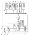
- FIG. 1 is a block diagram showing a configuration of an in-vehicle communication device according to a first embodiment
- 2 is a diagram showing communication paths between the in-vehicle communication device, an external device, and the in-vehicle device in the first embodiment
- 2 is a hardware configuration diagram of a control unit of the in-vehicle communication device according to the first embodiment.
- FIG. FIG. 2 is a diagram showing application profile configuration management of the in-vehicle communication device according to the first embodiment.
- 4 is a diagram showing classification of received data in the in-vehicle communication device according to the first embodiment;
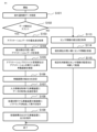
- 5 is a flowchart showing processing of outside-vehicle received data by the in-vehicle communication device according to the first embodiment
- 4 is a flowchart showing processing of vehicle exterior transmission data by the vehicle-mounted communication device according to the first embodiment
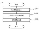
- 5 is a flowchart showing an application execution process in a processing unit designated by the in-vehicle communication device according to the first embodiment
- 6 is a flowchart showing an output process of a processing result of an application in an in-vehicle device designated by the in-vehicle communication device according to the first embodiment
- 4 is a flowchart showing normal processing of an in-vehicle device to which the in-vehicle communication device according to the first embodiment is connected
- 4 is a diagram showing a priority management table in an application profile of the in-vehicle communication device according to the first embodiment
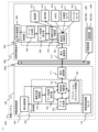
- FIG. 11 is a block diagram showing a configuration of an in-vehicle communication device according to a second embodiment.
- 13 is a flowchart showing a receiving process of an application in a portable information terminal designated by an in-vehicle communication device according to the second embodiment;
- 10 is a flowchart showing an application execution process in a portable information terminal designated by an in-vehicle communication device according to a second embodiment;
- 13 is a block diagram showing a configuration of an in-vehicle communication device to which an in-vehicle communication device according to a third embodiment is connected.
- FIG. FIG. 11 is a diagram showing a case where the portable information terminal according to the third embodiment is not moving in a vehicle.
- FIG. 13 is a diagram showing a case where a mobile information terminal to which an in-vehicle communication device according to a third embodiment is connected is moving in a vehicle.
- FIG. 13 is a flowchart showing a moving state determination process of a portable information terminal to which an in-vehicle communication device according to a third embodiment is connected;
- Fig. 1 is a block diagram showing a configuration example of an in-vehicle communication device 100 according to embodiment 1.
- Fig. 2 is a diagram showing communication paths between the in-vehicle communication device 100 and an external device and an in-vehicle device.
- the in-vehicle communication device 100 is connected to the in-vehicle devices installed in the vehicle, namely, a locator 300, a mobile information terminal 400, a navigation device 500, a GNSS 600, an in-vehicle network management device 700, and a TCU (Telematics Control Unit) 800, via an in-vehicle network 1002.
- These in-vehicle devices each having a processing device, control units 320, 420, 520, 620, 720, and 820, are installed arbitrarily in the vehicle 1000.
- the in-vehicle communication device 100 is one of the in-vehicle devices. These devices as a whole constitute an in-vehicle system 1001, which is mounted on the vehicle 1000.
- the in-vehicle network management device 700 is a device that manages the in-vehicle network 1002, and refers to the master device when a master/slave communication method is used.
- CAN Controller Area Network
- Body-ECU body control device
- the TCU refers to an in-vehicle embedded system that uses a cellular network to connect the vehicle to cloud services or other vehicles under the V2X standard. In this case, it is a device that connects the in-vehicle system 1001 to a network (cloud service) outside the vehicle.
- the in-vehicle device is not limited to the example configuration in which the devices, hardware, and software are connected as shown in FIG. 1, and the devices, hardware, and software installed in the vehicle 1000 may include a DMS (Driver Monitoring System), a head-up display (HUD), an instrument panel, an in-vehicle speaker, and the like.
- a DMS Driver Monitoring System
- HUD head-up display
- FIG. 2 shows an example in which a smartphone 400a and a smart watch 400b are connected.
- a tablet, a wearable terminal, a virtual reality (VR) device, an augmented reality (AR) device, and the like may also be used.
- VR virtual reality
- AR augmented reality
- connection between the in-vehicle device and the in-vehicle network 1002 does not need to be wired, and may be made by non-contact communication including Bluetooth (registered trademark) and infrared communication.
- Bluetooth registered trademark
- infrared communication When a mobile information terminal 400 owned by a passenger in the vehicle 1000 is brought into the vehicle, it is automatically connected via Bluetooth, becomes part of the in-vehicle system 1001, and can be used as an in-vehicle device.
- the in-vehicle communication device 100 is connected to devices outside the vehicle via the external vehicle communication unit 104.
- the in-vehicle communication device 100 is connected to devices external to the vehicle 1000, such as an in-vehicle communication device mounted on another vehicle 2000, a roadside unit 9100, the Internet 9200, and a server 9300 including a server on the cloud.
- an external vehicle communication unit is also provided in a mobile information terminal, a locator, a TCU, etc., to realize communication with devices outside the vehicle.
- the vehicle may be a four-wheeled vehicle, including a passenger car, truck, bus, etc.
- the vehicle may be a two-wheeled vehicle, including a motorcycle, moped, three-wheeled bike, and bicycle.
- the vehicle is not limited to these as a moving object.
- the in-vehicle communication device 100 has an internal communication unit 117 for connecting to the in-vehicle network 1002, an in-vehicle communication device sensor 116, and a control unit 120.
- the control unit 120 is composed of a transfer destination determination unit 101, a data processing instruction unit 102, a data generation unit 103, and an application profile management unit 105.
- the control unit 120 executes the functions of transfer destination determination, data processing instruction, data generation, and application profile management.
- the in-vehicle communication device sensor 116 is composed of a GNSS, an acceleration sensor, a gyro sensor, etc.
- the mobile information terminal 400, the locator 300, the navigation device 500, etc. are also equipped with sensors such as a GNSS, an acceleration sensor, and a gyro sensor.
- the in-vehicle network 1002 connects each device in the in-vehicle system 1001.
- the in-vehicle network 1002 may be, for example, a CAN (registered trademark) or a LAN (Local Area Network). Alternatively, a wireless network such as a wireless LAN or Bluetooth may be used.
- the control unit 120 is connected to other in-vehicle devices via the in-vehicle network 1002, exchanges data with these other in-vehicle devices, and issues instructions on tasks to be executed.
- FIG. 3 is a hardware configuration diagram of the control unit 120.
- the hardware configuration diagram of FIG. 3 can also be applied to the control units 320, 420, 520, 620, 720, and 820 of other in-vehicle devices, but the control unit 120 will be described below as a representative.
- the control unit 120 is an electronic control device for processing information input from the in-vehicle communication device sensor 116, the vehicle exterior communication unit 104, and the vehicle interior communication unit 117 of the in-vehicle communication device 100, and processing information output from the vehicle exterior communication unit 104 and the vehicle interior communication unit 117.
- Each function of the control unit 120 is realized by a processing circuit provided in the control unit 120.
- control unit 120 includes, as processing circuits, an arithmetic processing device 90 (computer) such as a CPU (Central Processing Unit), a storage device 91 that exchanges data with the arithmetic processing device 90, an input circuit 92 that inputs an external signal to the arithmetic processing device 90, and an output circuit 93 that outputs a signal from the arithmetic processing device 90 to the outside.
- an arithmetic processing device 90 such as a CPU (Central Processing Unit)
- storage device 91 that exchanges data with the arithmetic processing device 90
- input circuit 92 that inputs an external signal to the arithmetic processing device 90
- output circuit 93 that outputs a signal from the arithmetic processing device 90 to the outside.
- the arithmetic processing device 90 may be an ASIC (Application Specific Integrated Circuit), an IC (Integrated Circuit), a DSP (Digital Signal Processor), an FPGA (Field Programmable Gate Array), various logic circuits, and various signal processing circuits.
- the arithmetic processing device 90 may be a plurality of the same or different types, and each process may be shared and executed.
- the storage device 91 may be a RAM (Random Access Memory) configured to be able to read and write data from the arithmetic processing device 90, a ROM (Read only Memory) configured to be able to read data from the arithmetic processing device 90, or the like.
- the storage device 91 may be a non-volatile or volatile semiconductor memory such as a flash memory, an EPROM, or an EEPROM.
- the input circuit 92 is connected to various sensors, switches, and communication lines, including the output signal of the in-vehicle communication device sensor 116, the external communication unit 104, and the internal communication unit 117, and is equipped with an A/D converter, communication circuit, etc. that input the output signals of these sensors and switches and communication information to the arithmetic processing device 90.
- the output circuit 93 is equipped with a drive circuit, communication circuit, etc. that outputs control signals from the arithmetic processing device 90 to devices including the external communication unit 104 and the internal communication unit 117.
- Each function of the control unit 120 is realized by the arithmetic processing device 90 executing software (programs) stored in a storage device 91 such as a ROM, and working in cooperation with other hardware of the control unit 120 such as the storage device 91, input circuit 92, and output circuit 93. Note that each of these may be composed of software modules, or may be composed of a combination of software and hardware.
- the external-vehicle communication unit 104 is a device including a receiver that receives data from a moving object present in the vicinity of the vehicle 1000 and a transmitter that transmits data.
- the external-vehicle communication unit 104 can use a communication method such as a cellular network (registered trademark) such as LTE (Long Term Evolution) (registered trademark) or a fifth-generation mobile communication system (5G), a dedicated short-range communication (DSRC) dedicated to vehicle communication, or a Cellular-V2X.
- a cellular network registered trademark
- LTE Long Term Evolution
- 5G fifth-generation mobile communication system
- DSRC dedicated short-range communication
- DSRC is a one-way or two-way wireless communication technology that uses the 5.8 GHz ISM (Industrial Scientific and Medical Band) band, designed specifically for wireless communication with vehicles, and is also known as dedicated narrowband communication or narrowband communication.
- ISM International Scientific and Medical Band
- Cellular-V2X is a standard for V2X (Vehicle to Everything) communication using wireless communication lines for mobile phones, released by 3GPP (Third Generation Partnership Project) (registered trademark), the standard for third-generation mobile communication systems. Implementation is recommended by the Five Generation Automotive Association (5GAA), a global cross-industry organization.
- 5GAA Five Generation Automotive Association
- the in-vehicle communication device 100 communicates directly with vehicles surrounding the vehicle 1000 to support safe driving and improve autonomous driving, and can connect to a server including the cloud to obtain information on surrounding vehicles, traffic information, entertainment information, and the like.
- a server including the cloud to obtain information on surrounding vehicles, traffic information, entertainment information, and the like.
- the vehicle communicates with surrounding vehicles and roadside units, in addition to the external communication unit 104, it may use any communication function of the device, such as a TCU communication function, a smartphone communication function, or a communication function of another in-vehicle device.
- control unit 120 and one external vehicle communication unit 104 are shown. However, there may be multiple control units 120 and multiple external vehicle communication units 104, and multiple control units 120 may cooperate to execute programs that realize each function. Multiple external vehicle communication units 104 may switch between the external vehicle communication units 104 that transmit and receive data depending on the type of data.
- the transfer destination determination unit 101 determines a delivery destination of the data received from the exterior communication unit 104 and the interior communication unit 117 based on the information notified from the application profile management unit 105.
- the transfer destination determination unit 101 delivers the received data to the determined route and device.
- the transfer destination determination unit 101 transfers the received data to the data processing instruction unit 102, and if the received data is to be processed by the mobile information terminal 400, the transfer destination determination unit 101 transfers the received data to the mobile information terminal 400.
- the data processing instruction unit 102 uses the received data to determine the need for vehicle control, driver assistance, and advice, such as autonomous driving control decisions, the need for driving assistance, and collision risk assessment.
- a driving assistance determination unit 118 may be provided exclusively to make these decisions.
- the data processing instruction unit 102 determines that assistance is necessary, it transmits the assistance contents to an in-vehicle device capable of displaying and speaking.
- the in-vehicle communication device 100 is not provided with a device capable of displaying and speaking, the assistance contents are notified to the mobile information terminal 400 via the transfer destination determination unit 101, enabling display and speaking.
- the in-vehicle communication device 100 is not equipped with a display or speech device
- the in-vehicle system 1001 may be realized by equipping the in-vehicle communication device 100 with a display or speech device.
- the data generation unit 103 may receive data from the on-board devices and sensors of the on-board devices mounted on the vehicle 1000 from the on-board communication device sensor 116 and the transfer destination determination unit 101, generate transmission data, and transmit it to the outside via the on-board communication device 100.
- the data generation unit 103 receives multiple pieces of sensor information and application processing results, it selects the data to be used based on the information notified from the application profile management unit 105 and generates the transmission data.
- the application profile management unit 105 manages applications (services) that can be provided by the in-vehicle system 1001, and notifies the data generation unit 103 and the transfer destination determination unit 101 of application profile information including sensor information used according to the applications provided by the in-vehicle system 1001 and device information that realizes functions required for the in-vehicle device.
- the application profile management unit 105 manages applications that can be provided by the in-vehicle system 1001, such as an automatic driving application, a safe driving support application, a traffic information provision application, and an entertainment application. In addition, as shown in FIG. 4, for example, the application profile management unit 105 manages combination information of a function required for generating data for a safe driving support application and an in-vehicle device having a device that realizes that function.
- Fig. 4 shows an example of a system configuration showing which devices are used to realize the functions and devices required for data generation of a safe driving assistance application, including a GNSS (positioning function), an acceleration sensor, a gyro sensor, a control unit (processor), a display unit (screen), a speech unit (speaker), a V2X in-vehicle communication device, and a V2N in-vehicle communication device.
- system configuration #0 in FIG. 4 shows an example of a system implemented using the in-vehicle communication device 100 and the mobile information terminal 400.
- System configuration #1 shows an example of a system implemented using the locator 300, navigation device 500, in-vehicle communication device 100, and TCU 800.
- System configuration #3 is implemented using the mobile information terminal 400 and in-vehicle communication device 100, but is implemented in a different combination from system configuration #0, for example using the mobile information terminal 400 for positioning, acceleration sensor, and gyro sensor.
- Figure 4 shows an example of implementing GNSS (positioning function) using the in-vehicle communication device sensor 116 of the in-vehicle communication device 100 in system configuration #0, the locator 300 in system configuration #1, and the mobile information terminal 400 in system configuration #2.
- the in-vehicle device selected in the application profile configuration is selected based on the type of sensor, the accuracy of the sensor, the reliability of the sensor output, the processing performance (processing load) of the control unit, the degree of communication congestion, etc.
- the application must be executed using the in-vehicle communication device 100 and the mobile information terminal 400, and system configuration #0 or system configuration #2 will be selected.
- control unit 120 of the in-vehicle communication device 100 can be used as a control unit (processor) as in system configuration #2.
- the in-vehicle communication device 100 needs to execute an autonomous driving application, there may be cases where it is desired to reduce the processing load rate of the control unit 120 of the in-vehicle communication device 100 so that the autonomous driving application can be executed with ease. In such cases, it is preferable to execute the software for the safe driving support application using the mobile information terminal 400. In such cases, system configuration #0 is selected.
- system configuration #2 will be selected.
- the mobile information terminal 400 is not connected to the in-vehicle system 1001 of the vehicle 1000. In that case, it is possible to cover the necessary functions using the in-vehicle communication device 100.
- the in-vehicle device with the most accurate sensor output information can be selected. This is because doing so will improve the accuracy of processing by the application.
- the most reliable in-vehicle device may be selected by placing emphasis on reliability rather than accuracy of the sensor output information. This is because doing so will also improve the reliability of processing by the application.
- a combination of in-vehicle devices may be selected so as to minimize the maximum value of the processing load rate of the control unit of the in-vehicle devices as a whole. In this way, the processing load of the control unit of the in-vehicle system 1001 as a whole can be improved by processing by the application.
- Fig. 11 is a diagram showing an example of a priority management table in the application profile of the in-vehicle communication device 100 according to the first embodiment.
- Fig. 11 shows an example in which the priority of an in-vehicle device available for each required function and device is evaluated as high, medium, or low.
- the priority indicating which device should be used to realize the GNSS (positioning function), acceleration sensor, gyro sensor, control unit (processor), display unit (screen), speech unit (speaker), V2X in-vehicle communication device, and V2N in-vehicle communication device as functions and devices required for data generation of a safe driving support application is shown.
- the application profile management unit 105 can determine the optimal combination of in-vehicle devices for each application profile configuration candidate by considering the priority. Specifically, the configuration candidates can be scored according to the priority, with 3 points for high, 2 points for medium, and 1 point, and evaluated based on the total points for each function and device.
- the priority of the control unit (processor) in the function and device column is highest for the mobile information terminal 400, followed by the navigation device 500 and the in-vehicle communication device 100, then the locator 300, and the TCU 800.
- the transfer destination determination unit 101 may transmit the received data to a device with a high priority control unit (processor). If the processing load of the control unit of a high priority device is high, the data may be sent to the device with the next highest priority, thereby distributing the processing load.
- a high priority control unit processor
- the processing results are output to the display unit (screen) and the speech unit (speaker) when executing a safe driving support application.
- the processing results may also be transmitted to a device outside the vehicle via the external vehicle communication unit 104.
- the application profile management unit 105 determines the system configuration.
- the application profile management unit 105 transmits application profile information that describes the combination of devices to be assigned to each function and device to the data generation unit 103 and the transfer destination determination unit 101.
- the in-vehicle communication unit 117 transmits the information to the in-vehicle device specified by the transfer destination determination unit 101.
- the in-vehicle communication device 100 may transmit the data notified from the data generation unit 103 to an external device via the external communication unit 104.
- the above-mentioned DSRC or C-V2X may be used as the communication method.
- the external communication unit 104 receives information from the in-vehicle communication device of the vehicle 2000 outside the vehicle 1000, the external roadside unit 9100, and various devices present in the vicinity of the vehicle 1000, and notifies the transfer destination determination unit 101.
- ⁇ Priority of received data> 5 is a diagram showing classification of received data of the in-vehicle communication device 100 according to the first embodiment.
- Data received from the outside-vehicle communication unit 104 is composed of a type, either application data or sensor information, a priority, either priority 1, priority 2, or priority 3, and the main body of the received data.
- Application data and sensor information with a high priority are preferentially transferred to the necessary in-vehicle device.
- Fig. 6 is a flowchart showing the processing of outside-vehicle received data by the in-vehicle communication device 100 according to the embodiment 1.
- the processing shown in Fig. 6 may be started every time the outside-vehicle communication unit 104 receives data. Alternatively, the processing may be executed at predetermined time intervals (e.g., 1 ms) and terminated if no received data is received during that time.
- the operation of the in-vehicle communication device 100 corresponds to the processing of a program of the in-vehicle communication device.
- the external communication unit 104 transmits the received data to the transfer destination determination unit 101.
- the transfer destination determination unit 101 receives the data, it determines the data type.
- step S102 it determines whether the type of the received data is application data. If the type is application data (determination is YES), the process proceeds to step S103. If the type is not application data (determination is NO), the type is sensor information, and the process proceeds to step S113.
- step S103 the transfer destination determination unit 101 obtains the priority of the received data.
- step S104 if there are multiple pieces of application data that are the received data, the application data are received in order of priority and the following processing is carried out.
- step S105 the application profile management unit 105 acquires information about the functions and devices required for the processing executed by the application. Specifically, it checks the in-vehicle devices that are connected to the in-vehicle system 1001 and can be used. It then creates candidates for combinations of required devices.
- step S106 the most appropriate combination of devices is determined based on predetermined criteria.
- the application profile information is notified to the data generation unit 103 and the transfer destination determination unit 101.
- step S107 the application profile management unit 105 notifies the data generation unit 103 and the transfer destination determination unit 101 of application profile information including the sensor information to be used, depending on the service provided by the application.
- the application profile information is then transmitted from the in-vehicle communication unit 117, and the data processing instruction unit 102 instructs the in-vehicle device that acquires the input information required to execute the application's processing to acquire and transmit the data.
- step S108 the application profile management unit 105 designates a control device to which the application software data is to be transferred, and transmits the designation from the transfer destination determination unit 101 via the in-vehicle communication unit 117. Then, the data processing instruction unit 102 instructs the execution of application processing. Specifically, at the point in time when the input information required for application processing is transmitted, the control unit of the corresponding in-vehicle device executes the processing and transmits the processing results.
- step S109 the application profile management unit 105 notifies the data generation unit 103 and the transfer destination determination unit 101 of application profile information including the in-vehicle device that outputs the processing result according to the service provided by the application. Then, the application profile information is transmitted from the in-vehicle communication unit 117, and the data processing instruction unit 102 instructs the in-vehicle device that executes the output of the application processing to output the processing result.
- the control unit of the corresponding in-vehicle device executes the processing and outputs the processing results to the display unit (screen), speech unit (speaker), etc. Then, the processing ends.
- step S113 the forwarding destination determination unit 101 obtains the priority of the received data.
- step S114 if there is more than one piece of sensor information that is received data, the sensor information is received in order of priority and the following process is carried out.
- step S115 the transfer destination determination unit 101 determines the delivery destination of the received data based on the application profile information notified by the application profile management unit 105.
- the transfer destination determination unit 101 delivers the received data to the in-vehicle device via the determined route. Then, the process ends.
- Steps S105 and S106 in FIG. 6 correspond to an application execution allocation determination step in which the application profile management unit 105 determines a combination of in-vehicle devices required for obtaining and transmitting input information required to execute an application, executing the processing of the application based on the transmitted input information, and outputting the processing results of the executed application.
- Steps S107 to S109 in FIG. 6 correspond to an application execution instruction step in which the data processing instruction unit 102 instructs the combination of in-vehicle devices determined by the application profile management unit 105 to obtain and transmit input information, to execute processing based on the transmitted input information, and to output the results of the executed processing.
- ⁇ Transmission process> 7 is a flowchart showing the processing of vehicle exterior transmission data of the in-vehicle communication device 100 according to the first embodiment.
- the processing shown in FIG. 7 may be started every time the vehicle exterior communication unit 104 transmits. Alternatively, the processing may be executed at predetermined time intervals (e.g., 1 ms), and the processing may be terminated if no data to be transmitted occurs during that time.
- the application profile management unit 105 specifies in the application profile that the processing output of the executed application is to be transmitted to a device outside the vehicle via the vehicle exterior communication unit 104.
- step S201 the data generation unit 103 generates data to be sent from the transmitted processing results based on the application profile information notified by the application profile management unit 105.
- step S202 the data generated by the data generation unit 103 is transmitted to the vehicle exterior communication unit 104. Then, in step S203, the vehicle exterior communication unit 104 transmits the transmitted data outside the vehicle, and ends the process.
- Fig. 8 is a flowchart showing the execution process of an application in a processing unit designated by the in-vehicle communication device 100 according to the first embodiment.
- the process shown in Fig. 8 shows the process of the in-vehicle device instructed by the data processing instruction unit 102 to execute an application.
- This process is executed by the processing unit of the in-vehicle device in response to transmission of input information.
- the process may be started in response to the transmission of input information as a trigger. Alternatively, the process may be executed at predetermined time intervals (e.g., 1 ms), and may be terminated if no transmission of input information occurs during that time.
- step S301 the in-car device reads the transmitted input information. Then, in step S302, the application is executed by the control unit of the in-car device.
- step S303 the control unit of the in-vehicle device transmits the processing result to the in-vehicle network 1002. This transmits the processing result to the in-vehicle device that outputs it. The processing then ends.
- Fig. 9 is a flowchart showing the output process of the processing result of the application in the in-vehicle device specified by the in-vehicle communication device 100 according to the first embodiment.
- the process shown in Fig. 9 shows the process of the in-vehicle device instructed by the data processing instruction unit 102 to output the processing result of the application.
- the process is executed by the processing unit of the in-vehicle device when the processing result is transmitted.
- the process may be started by being triggered by the transmission of the processing result. Alternatively, the process may be executed at predetermined time intervals (e.g., 1 ms), and may be terminated if no transmission of the processing result occurs during that time.
- step S401 the in-vehicle device reads the transmitted processing results. Then, in step S402, the in-vehicle device outputs the results using a display unit (screen) and a speech unit (speaker), etc. Then, processing ends.
- Fig. 10 is a flowchart showing normal processing of an in-vehicle device to which the in-vehicle communication device 100 according to the first embodiment is connected.
- Each in-vehicle device connected to the in-vehicle system 1001 executes normal processing in addition to processing based on instructions from the in-vehicle communication device 100 related to an application, such as obtaining input information, transmitting input information, executing processing, transmitting processing results, and outputting processing results.
- Fig. 10 is a flowchart illustrating this normal processing. This processing may be executed every time data required for processing is transmitted.
- step S501 the in-vehicle device reads the received data that has been transmitted. Then, in step S502, the in-vehicle device executes normal processing based on the received data. Then, in step S503, the processing result is transmitted using the in-vehicle network 1002. Thereafter, processing ends.
- the in-vehicle communication device 100 is described as being mounted on the vehicle 1000 and configured to participate in the execution of applications together with other in-vehicle devices connected as the in-vehicle system 1001.
- the in-vehicle communication device 100 may be configured not to provide information acquired by the in-vehicle communication device sensor, and not to provide the control unit 120 of the in-vehicle communication device 100 as a processing device for application execution, but to operate using the other in-vehicle devices.
- functions and devices such as sensors, communications, control units, displays, and speech units are divided, and an example is shown in which the in-vehicle device to be used is selected.
- the range of division may be further refined.
- multiple functions and devices may be managed together.
- the application profile configurations can be compared and determined using the sensor accuracy required by the application, the reliability of the sensors, the processing load rate of the control unit, and the priority of applying the in-vehicle devices. Since the sensor information to be used can be selected, data appropriate for the service can be generated.
- the system can be realized at low cost by utilizing the existing equipment, devices, and functions provided in the in-vehicle system 1001 and minimizing the number of newly added devices and functions. Also, the system can be realized at low cost by utilizing the portable information terminal 400 held by the passenger to execute applications.
- the processing load of a high-priority function or device control unit when the processing load of a high-priority function or device control unit is high, the processing load can be distributed by requesting the device with the next highest priority to handle the situation.
- Second embodiment ⁇ Configuration of in-vehicle communication device and mobile information terminal> 12 is a block diagram showing a configuration of an in-vehicle communication device 100 according to embodiment 2.
- the same components as those in embodiment 1 are given the same reference numerals, and duplicated detailed descriptions are omitted.
- FIG. 12 of the second embodiment differs from the first embodiment in that it describes the detailed configuration of the mobile information terminal 400.
- the contents of the application are described on the assumption that a safe driving support application is executed.
- the control unit 120 of the in-vehicle communication device 100 and the control unit 120 of the mobile information terminal 400 differ from the first embodiment in that they are provided with dedicated driving support determination units 118, 418 that determine whether or not safe driving support is required.
- the mobile information terminal 400 further includes a control unit 420, an external vehicle communication unit 404, an internal vehicle communication unit 417, a GNSS 410, an acceleration sensor 411, a gyro sensor 412, a speech unit 413, and a display unit 414.
- the control unit 420 is also configured with a transfer destination determination unit 401, a data processing instruction unit 402, a data generation unit 403, and a driving assistance determination unit 418.
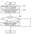
- FIG. 13 is a flowchart showing the reception processing of an application in the portable information terminal 400 designated by the in-vehicle communication device 100 according to the second embodiment.
- FIG. 13 shows the process that starts when the mobile information terminal 400 receives application data from the in-vehicle network 1002.
- the control unit 420 receives the application data from the in-vehicle network 1002 via the in-vehicle communication unit 417 of the mobile information terminal 400.
- step S602 the transfer destination determination unit 401 determines, based on the application profile information, whether the mobile information terminal 400 will execute the application processing or whether another in-car device will execute the application processing. If the mobile information terminal 400 will execute the processing (determination is YES), the process proceeds to step S603. If the mobile information terminal 400 will not execute the processing (determination is NO), the process ends.
- step S603 the control unit 420 of the mobile information terminal 400 reads the application data. Then, the process ends.
- Fig. 14 is a flowchart showing an application execution process in the portable information terminal 400 designated by the in-vehicle communication device 100 according to embodiment 2.
- Fig. 14 shows the process that starts when the portable information terminal 400 receives application data from the in-vehicle network 1002 and finishes reading the data.
- step S701 the control unit 420 of the mobile information terminal 400 reads instructions regarding input information required when executing the application based on the application profile information notified from the application profile management unit 105. It is determined whether the input information uses information input from a sensor possessed by the mobile information terminal 400.
- step S703 If the input information of the mobile information terminal 400 is to be used (determination is YES), proceed to step S703.
- step S703 information from the GNSS 410, acceleration sensor 411, and gyro sensor 412 of the mobile information terminal 400 is acquired as input information. Then, proceed to step S704.
- step S702 If the input information of the mobile information terminal 400 is not to be used in step S702 (determination is NO), the process proceeds to step S708. In step S708, the process waits for input information to be transmitted from another in-vehicle device via the in-vehicle network 1002, and acquires the input information. Then, the process proceeds to step S704.
- step S704 the control unit 420 of the mobile information terminal 400 executes the application processing. Then, in step S705, the processing result is transmitted via the in-vehicle network 1002.
- step S706 it is determined based on the application profile information whether the processing result is to be output by the mobile information terminal 400. If the processing result is to be output by the mobile information terminal 400 (determination is YES), the process proceeds to step S707. Then, the processing result is output to the display unit 414 and speech unit 413 of the mobile information terminal 400. Thereafter, the process ends.
- step S706 If in step S706 the processing result is not output by the mobile information terminal 400 (determination is NO), the processing ends. Since the processing result of the application is transmitted via the in-vehicle network 1002, the in-vehicle device that is instructed to output the processing result will output the processing result.
- the in-vehicle system 1001 can be realized by utilizing the functions of the mobile information terminal 400 separately from the in-vehicle communication device 100. Therefore, by minimizing the number of newly added functions and devices, the in-vehicle system 1001 can be realized at low cost, and applications can be executed appropriately.
- Third embodiment ⁇ Configuration of in-vehicle communication device and mobile information terminal> 15 is a block diagram showing a configuration of a mobile information terminal 400 connected to an in-vehicle communication device 100 according to embodiment 3.
- the same components as those in embodiments 1 and 2 are given the same reference numerals, and overlapping detailed descriptions are omitted.
- the third embodiment differs from the second embodiment in that the mobile information terminal 400 further includes a moving state determination unit 415.
- FIG. 16 is a diagram showing a case where the mobile information terminal 400 according to the third embodiment is not moving in the vehicle 1000.
- FIG. 17 is a diagram showing a case where the mobile information terminal 400 connected to the in-vehicle communication device 100 according to the third embodiment is moving in the vehicle 1000.
- FIG. 16 shows a case where the user carrying the mobile information terminal 400 is not in the vehicle.
- the mobile information terminal 400 and the in-vehicle communication device 100 transmit their respective location information and movement information as usual, and become aware of each other's presence.
- FIG. 17 shows a case where a user carrying a mobile information terminal 400 is aboard a vehicle 1000.
- the mobile information terminal 400 is connected to an in-vehicle network 1002 and also to an in-vehicle communication device 100.
- the transmission of position information and movement information from the mobile information terminal 400 is suppressed.
- the in-vehicle communication device 100 can represent the position information and movement information of the vehicle 1000. Only the in-vehicle communication device 100 periodically transmits information such as position information and movement information.
- Fig. 18 is a flowchart showing a moving state determination process of the portable information terminal 400 connected to the in-vehicle communication device 100 according to the embodiment 3.
- the flowchart of Fig. 18 may be executed by the control unit 420 of the portable information terminal 400 at predetermined time intervals (e.g., 1 ms). Also, the flowchart may be executed not at predetermined time intervals but in response to a predetermined event, such as each time communication is executed.
- step S801 the moving state determination unit 415 of the in-vehicle communication device 100 acquires information from the GNSS 410, acceleration sensor 411, and gyro sensor 412 of the mobile information terminal 400. Then, in step S802, the moving state determination unit 415 estimates whether the mobile information terminal 400 is moving in the vehicle 1000.
- the estimation method may be, but is not limited to, the moving state due to speed, and changes in the values of the acceleration sensor and gyro sensor.
- step S803 the movement state determination unit 415 determines whether the mobile information terminal 400 is moving in the vehicle 1000. If it is determined that the mobile information terminal 400 is moving in the vehicle 1000 (determination is YES), the process proceeds to step S804. If it is determined that the mobile information terminal 400 is not moving in the vehicle 1000 (determination is NO), the process ends.
- step S804 the mobile information terminal 400 prohibits the transmission of position information and movement information from the external vehicle communication unit 404.
- the moving state determination unit 415 may also transmit, via the in-vehicle network 1002, that the mobile information terminal 400 is moving together with the vehicle 1000. After determining the moving state once, the determination may be skipped for a certain period of time.
- the in-vehicle system 1001 in the third embodiment shows an example in which the mobile information terminal 400 suppresses communication
- the in-vehicle communication device 100 may suppress communication. Furthermore, communication may be suppressed not only for the mobile information terminal 400 but also for other in-vehicle devices.
- 100 In-vehicle communication device 102 Data processing instruction unit, 103, 403 Data generation unit, 104, 404 External vehicle communication unit, 105 Application profile management unit, 117, 417 In-vehicle communication unit, 118, 418 Driving support determination unit, 120 Control unit, 400 Portable information terminal, 1000 Vehicle, 1001 In-vehicle system, 1002 In-vehicle network
Landscapes
- Physics & Mathematics (AREA)
- General Physics & Mathematics (AREA)
- Traffic Control Systems (AREA)
Priority Applications (2)
| Application Number | Priority Date | Filing Date | Title |
|---|---|---|---|
| PCT/JP2023/014326 WO2024209664A1 (ja) | 2023-04-07 | 2023-04-07 | 車載通信装置、車載システム、および車載通信装置のアプリケーション処理方法 |
| JP2025512357A JP7774769B2 (ja) | 2023-04-07 | 2023-04-07 | 車載通信装置、車載システム、および車載通信装置のアプリケーション処理方法 |
Applications Claiming Priority (1)
| Application Number | Priority Date | Filing Date | Title |
|---|---|---|---|
| PCT/JP2023/014326 WO2024209664A1 (ja) | 2023-04-07 | 2023-04-07 | 車載通信装置、車載システム、および車載通信装置のアプリケーション処理方法 |
Publications (1)
| Publication Number | Publication Date |
|---|---|
| WO2024209664A1 true WO2024209664A1 (ja) | 2024-10-10 |
Family
ID=92971551
Family Applications (1)
| Application Number | Title | Priority Date | Filing Date |
|---|---|---|---|
| PCT/JP2023/014326 Ceased WO2024209664A1 (ja) | 2023-04-07 | 2023-04-07 | 車載通信装置、車載システム、および車載通信装置のアプリケーション処理方法 |
Country Status (2)
| Country | Link |
|---|---|
| JP (1) | JP7774769B2 (https=) |
| WO (1) | WO2024209664A1 (https=) |
Citations (3)
| Publication number | Priority date | Publication date | Assignee | Title |
|---|---|---|---|---|
| JP2020161010A (ja) * | 2019-03-28 | 2020-10-01 | 本田技研工業株式会社 | 車両管理システム |
| WO2021171828A1 (ja) * | 2020-02-27 | 2021-09-02 | 住友電気工業株式会社 | 車内外連携装置及び方法 |
| JP2022526178A (ja) * | 2019-04-12 | 2022-05-23 | ハーマン インターナショナル インダストリーズ インコーポレイテッド | 車載コンピューティングシステムのためのエラスティックコンピューティング |
-
2023
- 2023-04-07 JP JP2025512357A patent/JP7774769B2/ja active Active
- 2023-04-07 WO PCT/JP2023/014326 patent/WO2024209664A1/ja not_active Ceased
Patent Citations (3)
| Publication number | Priority date | Publication date | Assignee | Title |
|---|---|---|---|---|
| JP2020161010A (ja) * | 2019-03-28 | 2020-10-01 | 本田技研工業株式会社 | 車両管理システム |
| JP2022526178A (ja) * | 2019-04-12 | 2022-05-23 | ハーマン インターナショナル インダストリーズ インコーポレイテッド | 車載コンピューティングシステムのためのエラスティックコンピューティング |
| WO2021171828A1 (ja) * | 2020-02-27 | 2021-09-02 | 住友電気工業株式会社 | 車内外連携装置及び方法 |
Also Published As
| Publication number | Publication date |
|---|---|
| JPWO2024209664A1 (https=) | 2024-10-10 |
| JP7774769B2 (ja) | 2025-11-21 |
Similar Documents
| Publication | Publication Date | Title |
|---|---|---|
| KR101500472B1 (ko) | 차량 내외로 차량 관련 정보를 전송하는 방법 및 장치 | |
| EP3968116B1 (en) | Alarm apparatus and alarm method | |
| JP6916813B2 (ja) | デバイスの自動車のヘッドユニットへの接続確立の方法、並びにそのためのヘッドユニット及びシステム | |
| US20150304817A1 (en) | Mobile communication device and communication control method | |
| US20200257282A1 (en) | Vehicle control arbitration | |
| US11499839B2 (en) | Driving assistance device, control method, and non-transitory computer-readable medium storing program | |
| EP3044980B1 (en) | Communication system | |
| US20130238190A1 (en) | Vehicle-mounted application management device and vehicle-mounted application management method | |
| KR101651710B1 (ko) | 양방향 애드혹 네트워크 무선 통신에서의 차량들에 대한 제어 디바이스 | |
| CN113498017A (zh) | 用于支持车辆对万物通信的装置和方法以及包括该装置的系统 | |
| US11615500B2 (en) | Vehicle information processing apparatus, vehicle information processing system, and method of processing vehicle information | |
| CN102461080B (zh) | 双向adhoc网络无线电通信中的控制器 | |
| WO2018008192A1 (ja) | 運転支援装置 | |
| KR102270316B1 (ko) | 스마트단말기로 구성된 멀티비젼을 구비한 다채널 avm 시스템 | |
| JP7774769B2 (ja) | 車載通信装置、車載システム、および車載通信装置のアプリケーション処理方法 | |
| CN108701410A (zh) | 车辆用通信控制装置 | |
| WO2019150458A1 (ja) | 車載装置、生成方法、および、コンピュータプログラム | |
| JP2005286756A (ja) | 移動体間通信経路選択方法、無線通信装置および移動体 | |
| JP2021096509A (ja) | 通報装置、通報システムおよび通報方法 | |
| EP3537712A1 (en) | Method, system and computer program product for controlling a video call while driving a vehicle | |
| KR102777970B1 (ko) | 증강현실 기반 탑승 요청자 정보 제공 시스템 및 그 제어 방법 | |
| US20260129492A1 (en) | Control device, communication device, communication system, operation method, and storage medium | |
| KR20170002917A (ko) | 다중 스마트 장치와 연결되는 차량 및 그 제어방법 | |
| JP2004343507A (ja) | 車載端末 | |
| JP2019008547A (ja) | 制御装置、システム、制御方法、及びプログラム |
Legal Events
| Date | Code | Title | Description |
|---|---|---|---|
| 121 | Ep: the epo has been informed by wipo that ep was designated in this application |
Ref document number: 23932075 Country of ref document: EP Kind code of ref document: A1 |
|
| WWE | Wipo information: entry into national phase |
Ref document number: 2025512357 Country of ref document: JP |
|
| NENP | Non-entry into the national phase |
Ref country code: DE |
|
| 122 | Ep: pct application non-entry in european phase |
Ref document number: 23932075 Country of ref document: EP Kind code of ref document: A1 |