WO2024204426A1 - 荷電粒子ビーム照射システム、オフセット装置、制御方法 - Google Patents
荷電粒子ビーム照射システム、オフセット装置、制御方法 Download PDFInfo
- Publication number
- WO2024204426A1 WO2024204426A1 PCT/JP2024/012415 JP2024012415W WO2024204426A1 WO 2024204426 A1 WO2024204426 A1 WO 2024204426A1 JP 2024012415 W JP2024012415 W JP 2024012415W WO 2024204426 A1 WO2024204426 A1 WO 2024204426A1
- Authority
- WO
- WIPO (PCT)
- Prior art keywords
- charged particle
- particle beam
- electromagnet
- deflection
- isocenter
- Prior art date
- Legal status (The legal status is an assumption and is not a legal conclusion. Google has not performed a legal analysis and makes no representation as to the accuracy of the status listed.)
- Ceased
Links
Images


Classifications
-
- A—HUMAN NECESSITIES
- A61—MEDICAL OR VETERINARY SCIENCE; HYGIENE
- A61N—ELECTROTHERAPY; MAGNETOTHERAPY; RADIATION THERAPY; ULTRASOUND THERAPY
- A61N5/00—Radiation therapy
- A61N5/10—X-ray therapy; Gamma-ray therapy; Particle-irradiation therapy
-
- G—PHYSICS
- G21—NUCLEAR PHYSICS; NUCLEAR ENGINEERING
- G21K—HANDLING OF PARTICLES OR IONISING RADIATION NOT OTHERWISE PROVIDED FOR; IRRADIATION DEVICES; GAMMA RAY OR X-RAY MICROSCOPES
- G21K1/00—Arrangements for handling particles or ionising radiation, e.g. focusing or moderating
- G21K1/08—Deviation, concentration or focusing of the beam by electric or magnetic means
- G21K1/093—Deviation, concentration or focusing of the beam by electric or magnetic means by magnetic means
-
- G—PHYSICS
- G21—NUCLEAR PHYSICS; NUCLEAR ENGINEERING
- G21K—HANDLING OF PARTICLES OR IONISING RADIATION NOT OTHERWISE PROVIDED FOR; IRRADIATION DEVICES; GAMMA RAY OR X-RAY MICROSCOPES
- G21K5/00—Irradiation devices
- G21K5/04—Irradiation devices with beam-forming means
-
- H—ELECTRICITY
- H05—ELECTRIC TECHNIQUES NOT OTHERWISE PROVIDED FOR
- H05H—PLASMA TECHNIQUE; PRODUCTION OF ACCELERATED ELECTRICALLY-CHARGED PARTICLES OR OF NEUTRONS; PRODUCTION OR ACCELERATION OF NEUTRAL MOLECULAR OR ATOMIC BEAMS
- H05H13/00—Magnetic resonance accelerators; Cyclotrons
- H05H13/04—Synchrotrons
Definitions
- the present invention relates to a charged particle beam irradiation system that suppresses the dispersion function when the charged particle beam reaches the isocenter.
- Particle beam therapy using charged particle beams has traditionally been used as a form of cancer treatment.
- particle beam therapy a common technique is to irradiate the lesion with charged particle beams from multiple directions in order to increase the concentration of the dose while minimizing the impact on surrounding normal tissue.
- a rotating gantry is known as an irradiation device that irradiates the patient's lesion from all directions.
- the charged particle beam generated by the accelerator is transported to the rotating gantry, which is the therapeutic irradiation section, via a transport path that includes bending electromagnets to change the direction of travel of the charged particle beam, quadrupole electromagnets that cause the charged particle beam to converge or diverge, and steering electromagnets to fine-tune the direction of travel of the charged particle beam.
- the charged particle beam transported to the rotating gantry is scanned by a scanning electromagnet, and the lesion is divided into multiple layers in the direction of travel of the charged particle beam, allowing three-dimensional therapeutic irradiation.
- the charged particle beam extracted from the accelerator has a certain dispersion function before it reaches the isocenter.
- the dispersion function is a coefficient that expresses the correlation of the position deviation from the designed orbit caused by the deviation in the momentum of each charged particle that composes the charged particle beam. This dispersion function is generated when the charged particle beam passes through a bending electromagnet, and as a result, the irradiation position of the charged particle beam may be shifted from the isocenter, or the shape of the charged particle beam may deviate from the desired shape. For this reason, the dispersion function of the charged particle beam must be as close to zero as possible at the isocenter, and it is generally known that this dispersion function can be adjusted by using a quadrupole electromagnet.
- Patent Document 1 discloses an example of a charged particle beam irradiation device that uses a fixed port in a vertical direction, and discloses a technique for adjusting the dispersion function by providing a deflection electromagnet and a quadrupole electromagnet on a plane inclined from the horizontal plane.
- Patent Document 2 discloses a technology for adjusting the dispersion function by providing multiple quadrupole electromagnets in the rotating gantry.
- Patent Document 3 describes a technique for irradiating a lesion with a charged particle beam from multiple directions without using a rotating gantry.
- irradiation from multiple directions is achieved by providing a bending electromagnet at the end of the transport path of the charged particle beam, but this bending electromagnet generates a dispersion function in the vertical direction.
- the placement of a quadrupole electromagnet to make this dispersion function zero at the isocenter causes the problem of an increase in the size of the irradiation device.
- Patent Document 2 where the placement of the quadrupole electromagnet leads to an increase in the size of the rotating gantry.
- the present invention was made in consideration of the above problems, and aims to provide a charged particle beam irradiation system that can adjust the dispersion function generated by the bending electromagnets without placing a quadrupole electromagnet in the irradiation section of the charged particle beam irradiation device.
- a charged particle beam irradiation system includes an accelerator, an electromagnet capable of deflecting the charged particle beam emitted from the accelerator, a charged particle beam irradiation device that irradiates the charged particle beam from multiple directions toward the isocenter, and an offset unit that controls the dispersion function generated by the electromagnet so that it is suppressed at the isocenter.
- the charged particle beam irradiation system according to the present invention can suppress the dispersion function caused by the influence of the deflection electromagnets provided in the irradiation section at the isocenter without providing a quadrupole electromagnet in the irradiation section.
- by not providing a quadrupole electromagnet in the irradiation section it is possible to prevent the irradiation section from becoming enlarged.
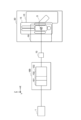
- FIG. 1 is a schematic diagram showing a configuration example of a charged particle beam irradiation system according to a first embodiment.
- FIG. 2 is a block diagram showing an example of the configuration of the offset unit.
- FIG. 3 is a diagram for explaining a mechanism for irradiating a charged particle beam by the charged particle beam irradiation device.
- FIG. 4 is a top view of a configuration example of the charged particle beam irradiation system according to the first embodiment.
- FIG. 5A is a diagram showing a schematic example of a dispersion function when an offset unit is not used
- FIG. 5B is a diagram showing a schematic example of a dispersion function when an offset unit is used.
- FIG. 6 shows an example of the configuration of a charged particle beam irradiation system according to the second embodiment in the case where a rotating gantry is used.
- 7A and 7B are diagrams showing modified examples of the offset portion.
- the accelerator 1 side in the path in which the charged particle beam is transported from the accelerator 1 to the isocenter O, the accelerator 1 side may be referred to as the upstream side, and the isocenter side may be referred to as the downstream side.
- the charged particle beam irradiation device 50 the charged particle beam may be irradiated from the irradiation nozzle 11 toward the isocenter.
- a transport path may be provided between the accelerator 1 and the offset section 100 as a transmission path for transporting the charged particle beam.
- This transport path deflects the charged particle beam extracted from the accelerator 1 as necessary and transmits it to the desired position, i.e., the entrance port of the offset section 100.
- Such a transport path may include a deflection electromagnet, a quadrupole electromagnet, a steering electromagnet, etc. as necessary.
- the offset unit 100 is a device provided to suppress the dispersion function generated in the irradiation device, and is a device for intentionally generating a dispersion function in the charged particle beam in advance so that the dispersion function generated in the irradiation device is as close to zero as possible at the isocenter.
- the dispersion function is a coefficient that represents the correlation of the positional deviation from the design orbit caused by the deviation in momentum of each charged particle that constitutes the charged particle beam, and when the charged particle beam is deflected by a deflection electromagnet, a positional deviation occurs from the desired position, and indicates the value of the positional deviation.
- the smaller this positional deviation the better, and it is preferable for it to be zero.
- the offset unit 100 includes a first deflection electromagnet 101, a quadrupole electromagnet 102, a second deflection electromagnet 103, and an offset control unit 110.
- the charged particle beam from the accelerator 1 is incident on the first deflection electromagnet 101 of the offset unit 100.
- the charged particle beam deflected by the first deflection electromagnet 101 is adjusted by the quadrupole electromagnet 102.
- the charged particle beam adjusted by the quadrupole electromagnet 102 is deflected again by the second deflection electromagnet 103.
- FIG. 1 the offset unit 100, as shown in FIG.
- the dispersion function generated in the offset unit 100 is controlled by the offset control unit 110 that can control the offset unit 100, and the first deflection electromagnet 101, quadrupole electromagnet 102, and second deflection electromagnet 103 are controlled.
- the offset control unit 110 may be a computer system that calculates the excitation amount of the quadrupole electromagnet 102 based on the deflection angle and irradiation angle of the distribution electromagnet 70 and the deflection electromagnet 80 and instructs the quadrupole electromagnet 102 on the excitation amount, and may execute the process by a program stored in a memory (not shown), or may be realized by a dedicated circuit that executes the control. Furthermore, the offset control unit 110 may also control the first deflection electromagnet 101 and the second deflection electromagnet 103.
- the offset control unit 110 may calculate in advance by simulation the excitation amount of the quadrupole electromagnet 102 according to the value of the dispersion function to be generated for each of multiple combinations of the deflection angle and irradiation angle of the sorting electromagnet 70 and the bending electromagnet 80, store each combination as a control table, and control it to appropriately control the excitation amount of the quadrupole electromagnet 102.
- the charged particle beam which has generated a dispersion function by the offset unit 100, passes through the distribution electromagnet 70 and the deflection electromagnet 80 and reaches the isocenter.
- the offset unit 100 controls the beam so that no dispersion function is generated (it becomes 0) when it is output from the second deflection electromagnet 103, and the charged particle beam does not have a dispersion function when it enters the distribution electromagnet 70.
- FIG. 3(a) shows examples of multiple beam paths that differ for each deflection angle ⁇ and convergence angle ⁇ .
- the traveling direction of the charged particle beam is the X-axis
- the direction of the magnetic field generated by the deflection electromagnet 80 is the Z-axis
- the direction perpendicular to the X-axis and Z-axis is the Y-axis.
- the deflection electromagnet 80 is configured to converge the charged particle beam incident from a wide range of deflection angles ⁇ with respect to the X-axis on the XY plane to the isocenter O.
- the charged particle beam passes through the distribution electromagnet and the deflection electromagnet 80 in a straight line and reaches the isocenter.
- the irradiation nozzle 11 is omitted, and for the sake of simplicity, the isocenter O is set as the origin of the XYZ space, and the upstream side (the accelerator side, the left side of the paper in FIG. 3(a)) is set as the positive direction of the X-axis.
- the deflection electromagnet 70 deflects the incident charged particle beam as necessary. In some cases, the deflection electromagnet 70 allows the incident charged particle beam to travel in a straight line without deflecting it.
- the deflection electromagnet 80 comprises one or more coil pairs, which generate a uniform magnetic field (effective magnetic field regions 81a, 81b) oriented in a direction perpendicular to the direction of travel of the charged particle beam and the direction of spread of the deflection angle ⁇ of the charged particle beam (Z-axis direction in the figure), and are arranged on either side of the path of the charged particle beam.
- the effective magnetic field region generated by one coil pair of the deflection electromagnet 80 has a crescent shape in the XY plane as shown in FIG. 3(a), and details will be described later.
- the gap between the opposing coil pairs through which the charged particle beam passes (distance in the Z-axis direction) is sufficiently small compared to the range in which the charged particle beam spreads on the XY plane, so the spread of the charged particle beam in the Z-axis direction is not taken into consideration here.
- Figure 3(b) is a cross-sectional view of the deflection electromagnet 80 taken along line A-A.
- the deflection electromagnet 80 preferably comprises at least two pairs of coils 84a, 84b. Magnetic poles 85a, 85b are built into the coils 84a, 84b, respectively, and a yoke 86 is connected to the magnetic poles 85a, 85b.
- a power supply (not shown) is connected to the deflection electromagnet 80, and when a current (excitation current) is supplied from the power supply to the coil pairs 84a, 84b, the deflection electromagnet 80 is excited, and effective magnetic field regions 81a, 81b (collectively referred to as effective magnetic field region 81) are formed.
- the range of the effective magnetic field region 81a and the range of the effective magnetic field region 81b may be different (asymmetric). For example, if the range of the positive (+Y-axis) deflection angle ⁇ and the range of the negative (-Y-axis) deflection angle ⁇ are asymmetric, the effective magnetic field regions 81a and 81b can be formed accordingly asymmetrically, thereby reducing the amount of unused effective magnetic field region.
- the deflection angle ⁇ and the irradiation angle ⁇ which will be described later, are the angles of the path of the charged particle beam relative to the X-axis on the XY plane.
- the magnetic fields of the effective magnetic field region 81a and the effective magnetic field region 81b are in opposite directions.
- the deflection angle ⁇ of the charged particle beam incident on the deflection electromagnet 80 is controlled by the deflection electromagnet 70.
- the deflection electromagnet 70 generates a magnetic field oriented in a direction (Z-axis in the figure) perpendicular to the traveling direction (X-axis in the figure) of the charged particle beam supplied from the accelerator (not shown), and is equipped with an electromagnet that deflects the passing charged particle beam, and a control unit that controls the strength and direction of the magnetic field (both not shown).
- the deflection electromagnet 70 deflects the charged particle beam in the XY plane by controlling the strength and direction (Z-axis direction) of the magnetic field, and emits the charged particle beam deflected at the deflection angle ⁇ at the deflection origin Q to the deflection electromagnet 80.
- the deflection origin Q and the isocenter O are on the X-axis (on the same horizontal plane).
- the formula for forming the effective magnetic field region 81a of the deflection electromagnet 80 will be described with reference to FIG. 3(c). Note that in this embodiment, deflection of the charged particle beam in the Z-axis direction is not taken into consideration, so the formation of the effective magnetic field region in the XY plane will be described. The effective magnetic field region 81a of the deflection electromagnet 80 will be described, but the same applies to the effective magnetic field region 81b, so its description will be omitted.
- the boundaries of the effective magnetic field region 81a on the output side 83 of the deflection electromagnet 80 for the charged particle beam are determined to be within a range at an equal distance r1 from the isocenter O.
- the boundaries of the effective magnetic field region 81a on the input side 82 of the deflection electromagnet 80 for the charged particle beam are determined based on the relational expressions (1) to (5) described below, so that the incident charged particle beam is deflected at a deflection angle ⁇ at an imaginary deflection origin Q located at a predetermined distance L from the isocenter O, and converges on the isocenter O.
- the imaginary deflection origin Q is the point at which it is assumed that the charged particle beam receives a kick of the deflection angle ⁇ over an extremely short distance at the center of the distribution electromagnet 70.
- the charged particle beam transported at a deflection angle ⁇ enters at an arbitrary point P1 on the boundary of the effective magnetic field region 81a on the entrance side 82, performs a circular motion with a radius of curvature r2 within the effective magnetic field region 81a (the central angle at this time is ( ⁇ + ⁇ )), exits at a point P2 on the boundary of the effective magnetic field region 81a on the exit side 83, and is irradiated toward the isocenter O.
- points P1 and P2 are on an arc with a radius r2 and a central angle of ( ⁇ + ⁇ ).
- the shape and arrangement of the coil pair 84a and magnetic pole 85a of the deflection electromagnet 80 can be adjusted, and the current flowing through the coil pair 84a can be adjusted to adjust the shape of the boundary of the effective magnetic field region 81a.
- the boundary is determined so that the distance between any point P2 on the boundary of the effective magnetic field region 81a on the exit side 83 and the isocenter O is equal to r1, r2 is determined from equation (5) by adjusting the magnetic flux density B of the effective magnetic field region 81a, and the boundary of the effective magnetic field region 81a on the entrance side 82 is determined so that the distance R between point P1 on the boundary of the effective magnetic field region 81a on the entrance side 82 and the deflection origin Q has the relationship of equation (4).
- the maximum value of ⁇ in equation (3) is the maximum deflection angle ⁇ MAX.
- the deflection origin Q it is preferable to adjust the positions of the deflection origin Q, the deflection electromagnet 80, and the isocenter O so that the charged particle beam passing through the deflection origin Q converges on the isocenter O without being deflected by the deflection electromagnet 80, since this makes it possible to simplify the device configuration.
- the boundary between the effective magnetic field regions 81a, 81b of the deflection electromagnet 80 obtained as described above is an ideal shape for converging the charged particle beam to the isocenter O.
- the excitation amount (magnetic flux density B) of the deflection electromagnet 80 can be fine-tuned in advance for each deflection angle ⁇ , the information is stored in the power supply device, and the deflection angle ⁇ and the amount of current of the deflection electromagnet 80 can be controlled so that they are linked, thereby deflecting the charged particle beam to match the isocenter O.
- the non-uniformity of the magnetic field distribution can be predicted in advance, it is also possible to fine-tune the trajectory of the charged particle beam by correcting the shape and arrangement of the coil pairs 84a, 84b and magnetic poles 85a, 85b of the deflection electromagnet 80.
- FIG. 4 is a top view showing a schematic diagram of a charged particle beam irradiation system.
- the charged particle beam irradiation system at least the offset unit 100, the distribution electromagnet 70, and the deflection electromagnet 80 are arranged in a straight line. That is, the deflection direction of the charged particle beam deflected by the distribution electromagnet 70 and the deflection electromagnet 80 is vertical.
- the accelerator 1 may or may not be arranged in a straight line with the offset unit 100, the distribution electromagnet 70, and the deflection electromagnet 80.
- Fig. 5(a) is a diagram for explaining the dispersion function when the offset unit 100 is not present
- Fig. 5(b) is a diagram for explaining the dispersion function when the offset unit 100 is present.
- FIG. 5A is a schematic diagram showing the configuration of a charged particle beam irradiation system without an offset unit 100, showing an example of a distribution electromagnet 70, a deflection electromagnet 80, and a trajectory of a charged particle beam irradiated to an isocenter via these.
- the lower part of FIG. 5A shows an example of a dispersion function of a charged particle beam, showing an example of a correspondence between the distribution electromagnet 70, the deflection electromagnet 80, and the isocenter.
- a dispersion function is generated in the charged particle beam by being deflected via the distribution electromagnet 70.
- FIG. 5(b) is a schematic diagram showing the configuration of a charged particle beam irradiation system without an offset unit 100, and shows an example of the trajectory of the charged particle beam irradiated to the isocenter via the offset unit 100, the distribution electromagnet 70, and the bending electromagnet 80.
- the lower part of FIG. 5(b) shows an example of the dispersion function of the charged particle beam, showing an example of the correspondence between the distribution electromagnet 70, the bending electromagnet 80, and the isocenter.
- a dispersion function is generated in the charged particle beam by being deflected by the first bending electromagnet 101 and the second bending electromagnet 103 provided in the offset unit 100.
- the dispersion function generated when the charged particle beam is deflected using the distribution electromagnet 70 and the deflection electromagnet 80 arranged in the charged particle beam irradiation device 50 is intentionally generated in the offset unit 100 arranged in front of the distribution electromagnet 70, and the dispersion function at the isocenter O can be made zero by making the charged particle beam irradiated into the distribution electromagnet 70.
- the charged particle beam irradiation device 50 that is, in the treatment room 30, it is possible to converge the charged particle beam to the isocenter O (suppress the dispersion function of the charged particle beam at the isocenter O, and preferably make it zero) without arranging a quadrupole electromagnet for making the dispersion function zero. Therefore, by not arranging a quadrupole electromagnet, it is possible to prevent the charged particle beam irradiation device 50 from becoming enlarged. As a result, it is possible to make the treatment room 30 compact.
- FIG. 6 is a block diagram showing a schematic configuration of a charged particle beam irradiation system according to the second embodiment.
- the difference between the block diagram shown in FIG. 6 and the block diagram shown in FIG. 1 is the difference in the charged particle beam irradiation device, and the other configuration is the same as that of the first embodiment.
- the charged particle beam irradiation system includes an accelerator 1, a first offset unit 100a, a second offset unit 100b, and a rotating gantry 500.
- the rotating gantry 500 corresponds to the charged particle beam irradiation device in the second embodiment.
- the rotating gantry 500 can irradiate the charged particle beam toward the isocenter from multiple directions by rotating the irradiation nozzle 91 (irradiation unit) around the patient.
- the incident path 601 along which the charged particle beam is incident on the rotating gantry 500 also indicates the rotation axis of the rotating gantry 500.
- the accelerator 1 is the same as in the first embodiment, so a description thereof will be omitted.
- the first offset unit 100a is also similar to the offset unit 100 in the first embodiment, and is composed of a first deflection electromagnet 101a, a quadrupole electromagnet 102a, and a second deflection electromagnet 103a, and deflects the charged particle beam in the vertical direction to emit a charged particle beam that generates the desired dispersion function in the vertical direction.
- the second offset unit 100b like the first offset unit 100a, has a quadrupole electromagnet between two deflection electromagnets, with the third deflection magnet 101b, the quadrupole electromagnet 102b, and the fourth deflection electromagnet 103b arranged in this order, and is arranged on the path of the charged particle beam.
- the second offset unit 100b has a configuration in which the entire configuration is rotated 90 degrees with respect to the first offset unit 100a. That is, while the first offset unit 100a deflects the charged particle beam in the vertical direction to generate a vertical dispersion function, the second offset unit 100b deflects the charged particle beam in the horizontal direction to generate a horizontal dispersion function.
- the first offset unit 100a can be rephrased as a vertical offset unit
- the second offset unit 100b can be rephrased as a horizontal offset unit. This allows the rotating gantry 500 to be adjusted to suppress (preferably make zero) the dispersion function at isocenter 0 in both the vertical and horizontal directions, regardless of the angle at which it is tilted relative to the patient.
- the offset control unit 110a may, for example, calculate the excitation amount of the quadrupole electromagnet 102a according to the value of the dispersion function to be generated for various rotation angles of the rotating gantry 500 centered on the axis 601 and based on the horizontal direction, by simulation, store the combinations as a control table, and control them to appropriately control the excitation amount of the quadrupole electromagnet 102a. In this way, the first offset unit 100a can control the dispersion function in the vertical direction.
- a trained model that has learned the relationship between the rotation angle of the axis 601 and the desired excitation amount of the quadrupole electromagnet 102 for that rotation angle may be used, and the rotation angle from the reference position of the rotating gantry 500 may be input to the trained model to obtain the excitation amount of the quadrupole electromagnet 102b.
- the rotation angle is used here, this may be replaced by, for example, the coordinate value of the irradiation nozzle 91 of the rotating gantry 500.
- the offset control unit 110b may, for example, calculate the excitation amount of the quadrupole electromagnet 102b according to the value of the dispersion function to be generated for various rotation angles of the rotating gantry 500 centered on the axis 601 and based on, for example, the vertical direction (or the horizontal direction), by simulation, store the combinations as a control table, and control them to appropriately control the excitation amount of the quadrupole electromagnet 102a. In this way, the second offset unit 100b can control the dispersion function in the horizontal direction.
- a trained model that has learned the relationship between the rotation angle of the axis 601 and the corresponding desired excitation amount of the quadrupole electromagnet 102b may be used, and the rotation angle from the reference position of the rotating gantry 500 may be input to the trained model to obtain the excitation amount of the quadrupole electromagnet 102b.
- the rotation angle is used here, this may be replaced by, for example, the coordinate value of the irradiation nozzle 91 of the rotating gantry 500.
- the offset unit control unit (not shown) controls the first offset unit 100a and the second offset unit 100b.
- the offset control units 110a and 110b control the excitation amounts of the quadrupole electromagnets of the first offset unit 100a and the second offset unit 100b so that the charged particle beam is incident on the rotating gantry 500 in advance, so that the vertical and horizontal components of the dispersion function generated by the rotation angle of the rotation axis 601 in the rotating gantry 500 and the multiple deflection electromagnets provided in the rotating gantry 500 are both suppressed (preferably zero) at the isocenter.
- ⁇ Summary> As shown in the second embodiment, even in a charged particle beam irradiation system in which a rotating gantry including a deflection magnet is used as an irradiation device, by providing two offset units for deflecting in the vertical and horizontal directions, it is possible to suppress the dispersion function of the charged particle beam at the isocenter, preferably to make it 0, without disposing a quadrupole magnet in the irradiation device, as in the first embodiment. Therefore, it is possible to suppress the enlargement of the irradiation device.
- the charged particle beam irradiation system and the offset unit 100 shown in the above embodiment are not limited to the aspects shown in the above embodiment. They can be appropriately modified within the knowledge of those skilled in the art. Various modified examples will be described below.
- the basic configuration of the offset unit 100 is described as being configured in such a manner that a quadrupole electromagnet is sandwiched between two deflection electromagnets, but the configuration of the offset unit 100 is not limited to the configuration shown in the above embodiment.
- the offset section 100 may also be configured to include quadrupole electromagnets 104, 105 downstream of the second deflection electromagnet 103 (on the charged particle beam irradiation device side).
- quadrupole electromagnets 104, 105 downstream of the second deflection electromagnet 103 (on the charged particle beam irradiation device side).
- an example is shown in which two quadrupole electromagnets 104, 105 are included, but the number of quadrupole electromagnets is not limited to two, and may be one, or three or more.
- the role of the quadrupole electromagnets 104 and 105 in the transport path is to suppress the divergence of the charged particle beam, which has a dispersion function, in the second bending electromagnet 103, which causes large losses during transport, and to adjust the charged particle beam.
- the offset unit 100 is shown as being disposed between the accelerator 1 and the distribution electromagnet 70, but it goes without saying that the configuration shown in FIG. 7(a) can also be used as the offset units 100a and 100b in the second embodiment described above.
- one offset unit 100 is provided. This allows the charged particle beam to be adjusted in the height direction and incident on the charged particle beam irradiation device. On the other hand, there are also cases where it is desired to give the charged particle beam emitted from the offset unit 100 a dispersion function without changing the height of the charged particle beam and to function as an offset unit, i.e., to make the dispersion function of the charged particle beam at the isocenter zero.
- the configuration can be realized as shown in FIG. 7(b).
- a second offset section 100c may be provided that has the same configuration as the first offset section 100a and is arranged symmetrically to the first offset section 100a in the traveling direction of the charged particle beam.
- the first offset section 100a is composed of a first deflection electromagnet 101a, a quadrupole electromagnet 102a, and a second deflection electromagnet 103a, and this configuration is the same as the offset section 100 shown in embodiment 1.
- the second offset section 100c is configured to be symmetrical with the first offset section 100a at the center of the page, and is configured such that the first deflection electromagnet 101c, the quadrupole electromagnet 102c, and the second deflection electromagnet 103c are provided facing the second deflection electromagnet 103a.
- the offset control section controls the excitation amount of the quadrupole electromagnets 102a, 102c in both the first offset section 100a and the second offset section 100c.
- the offset units 100, 100a, and 100b are provided on the path before the electromagnets in the case where the charged particle beam is deflected by electromagnets (distributing electromagnets, deflecting electromagnets, etc.) after the offset unit 100 on the path until the charged particle beam is transported from the accelerator 1 to the isocenter, and a dispersion function is generated in the charged particle beam, and a quadrupole electromagnet for adjusting the dispersion function after deflection is not provided, or cannot be provided, or is difficult to provide.
- the offset units 100, 100a, and 100b are preferably provided at the final stage (the most downstream position) of the path on which the charged particle beam is transported from the accelerator 1 to the charged particle beam irradiation device 50 or the rotating gantry 500.
Landscapes
- Engineering & Computer Science (AREA)
- Physics & Mathematics (AREA)
- Health & Medical Sciences (AREA)
- Biomedical Technology (AREA)
- General Engineering & Computer Science (AREA)
- High Energy & Nuclear Physics (AREA)
- Spectroscopy & Molecular Physics (AREA)
- Pathology (AREA)
- Plasma & Fusion (AREA)
- Nuclear Medicine, Radiotherapy & Molecular Imaging (AREA)
- Radiology & Medical Imaging (AREA)
- Life Sciences & Earth Sciences (AREA)
- Animal Behavior & Ethology (AREA)
- General Health & Medical Sciences (AREA)
- Public Health (AREA)
- Veterinary Medicine (AREA)
- Particle Accelerators (AREA)
- Radiation-Therapy Devices (AREA)
Applications Claiming Priority (2)
| Application Number | Priority Date | Filing Date | Title |
|---|---|---|---|
| JP2023058513A JP2024145916A (ja) | 2023-03-31 | 2023-03-31 | 荷電粒子ビーム照射システム、オフセット装置、制御方法 |
| JP2023-058513 | 2023-03-31 |
Publications (1)
| Publication Number | Publication Date |
|---|---|
| WO2024204426A1 true WO2024204426A1 (ja) | 2024-10-03 |
Family
ID=92905723
Family Applications (1)
| Application Number | Title | Priority Date | Filing Date |
|---|---|---|---|
| PCT/JP2024/012415 Ceased WO2024204426A1 (ja) | 2023-03-31 | 2024-03-27 | 荷電粒子ビーム照射システム、オフセット装置、制御方法 |
Country Status (3)
| Country | Link |
|---|---|
| JP (1) | JP2024145916A (https=) |
| TW (1) | TW202441551A (https=) |
| WO (1) | WO2024204426A1 (https=) |
Citations (5)
| Publication number | Priority date | Publication date | Assignee | Title |
|---|---|---|---|---|
| US20100230620A1 (en) * | 2009-03-13 | 2010-09-16 | Brookhaven Science Associates, Llc | Achromatic and Uncoupled Medical Gantry |
| WO2013069379A1 (ja) * | 2011-11-08 | 2013-05-16 | 三菱電機株式会社 | 粒子線治療システムおよびそのビーム位置補正方法 |
| JP2015000090A (ja) * | 2013-06-13 | 2015-01-05 | 株式会社日立製作所 | 粒子線治療装置 |
| JP2018187308A (ja) * | 2017-05-12 | 2018-11-29 | 株式会社日立製作所 | 粒子線治療システム |
| US20200306561A1 (en) * | 2019-03-29 | 2020-10-01 | Varian Medical Systems Particle Therapy Gmbh | Non-achromatic compact gantry |
-
2023
- 2023-03-31 JP JP2023058513A patent/JP2024145916A/ja active Pending
-
2024
- 2024-03-27 WO PCT/JP2024/012415 patent/WO2024204426A1/ja not_active Ceased
- 2024-03-27 TW TW113111373A patent/TW202441551A/zh unknown
Patent Citations (5)
| Publication number | Priority date | Publication date | Assignee | Title |
|---|---|---|---|---|
| US20100230620A1 (en) * | 2009-03-13 | 2010-09-16 | Brookhaven Science Associates, Llc | Achromatic and Uncoupled Medical Gantry |
| WO2013069379A1 (ja) * | 2011-11-08 | 2013-05-16 | 三菱電機株式会社 | 粒子線治療システムおよびそのビーム位置補正方法 |
| JP2015000090A (ja) * | 2013-06-13 | 2015-01-05 | 株式会社日立製作所 | 粒子線治療装置 |
| JP2018187308A (ja) * | 2017-05-12 | 2018-11-29 | 株式会社日立製作所 | 粒子線治療システム |
| US20200306561A1 (en) * | 2019-03-29 | 2020-10-01 | Varian Medical Systems Particle Therapy Gmbh | Non-achromatic compact gantry |
Non-Patent Citations (1)
| Title |
|---|
| GIOVANNELLI ANNA CHIARA, MARADIA VIVEK, MEER DAVID, SAFAI SAIROS, PSOROULAS SERENA, TOGNO MICHELE, BULA CHRISTIAN, WEBER DAMIEN CH: "Beam properties within the momentum acceptance of a clinical gantry beamline for proton therapy", MEDICAL PHYSICS, vol. 49, no. 3, 1 March 2022 (2022-03-01), US , pages 1417 - 1431, XP093218478, ISSN: 0094-2405, DOI: 10.1002/mp.15449 * |
Also Published As
| Publication number | Publication date |
|---|---|
| TW202441551A (zh) | 2024-10-16 |
| JP2024145916A (ja) | 2024-10-15 |
Similar Documents
| Publication | Publication Date | Title |
|---|---|---|
| JP6364141B1 (ja) | 収束電磁石及び荷電粒子ビーム照射装置 | |
| US8658991B2 (en) | Particle beam irradiation apparatus utilized in medical field | |
| JP6387476B1 (ja) | 荷電粒子ビーム照射装置 | |
| JP2018533437A (ja) | エネルギデグレーダと、アクロマティックな最終のベンドシステムとを有する粒子治療用ガントリ | |
| WO2021260988A1 (ja) | 粒子加速器および粒子線治療装置 | |
| JP2011250910A (ja) | 粒子線治療装置 | |
| WO2013012702A1 (en) | Systems and methods for achromatically bending a beam of charged particles by about ninety degree during radiation treatment | |
| JP4474549B2 (ja) | 照射野形成装置 | |
| EP3885000A1 (en) | Charged particle irradiation apparatus | |
| JP6734610B1 (ja) | 超電導電磁石装置及び荷電粒子ビーム照射装置 | |
| US9099271B2 (en) | Method and system for operating electron guns in magnetic fields | |
| KR102628780B1 (ko) | 이온 빔을 조작하기 위한 기술들 및 장치 | |
| US11183370B2 (en) | Charged particle beam treatment apparatus | |
| WO2024204426A1 (ja) | 荷電粒子ビーム照射システム、オフセット装置、制御方法 | |
| JP7217208B2 (ja) | 走査電磁石および粒子線治療システム | |
| CN121335739A (zh) | 用于将不同能量的加速带电粒子从加速器的出口输送至靶标的射束输送系统 | |
| JP3964769B2 (ja) | 医療用荷電粒子照射装置 | |
| JP7165499B2 (ja) | 荷電粒子線治療装置 | |
| JP7589094B2 (ja) | 粒子線治療装置、および、粒子線治療装置の制御方法 | |
| JP2019195408A (ja) | スキャニング照射装置および粒子線治療システム、ならびにスキャニング照射装置の調整方法 | |
| US11058894B2 (en) | Particle beam therapy device and irradiation field forming method | |
| JP3547812B2 (ja) | 粒子ビーム装置及びそれを用いた医療装置 | |
| JP7045920B2 (ja) | 粒子線照射装置および粒子線治療システム | |
| JP2017038773A (ja) | 照射粒子線制御装置、荷電粒子線照射システム、および照射粒子線制御方法 | |
| JP2001231873A (ja) | 荷電粒子ビーム照射方法および装置 |
Legal Events
| Date | Code | Title | Description |
|---|---|---|---|
| 121 | Ep: the epo has been informed by wipo that ep was designated in this application |
Ref document number: 24780528 Country of ref document: EP Kind code of ref document: A1 |
|
| NENP | Non-entry into the national phase |
Ref country code: DE |
|
| 122 | Ep: pct application non-entry in european phase |
Ref document number: 24780528 Country of ref document: EP Kind code of ref document: A1 |