WO2024203648A1 - モータのコントローラ回路 - Google Patents
モータのコントローラ回路 Download PDFInfo
- Publication number
- WO2024203648A1 WO2024203648A1 PCT/JP2024/010831 JP2024010831W WO2024203648A1 WO 2024203648 A1 WO2024203648 A1 WO 2024203648A1 JP 2024010831 W JP2024010831 W JP 2024010831W WO 2024203648 A1 WO2024203648 A1 WO 2024203648A1
- Authority
- WO
- WIPO (PCT)
- Prior art keywords
- coefficient
- circuit
- output
- compensator
- controller
- Prior art date
- Legal status (The legal status is an assumption and is not a legal conclusion. Google has not performed a legal analysis and makes no representation as to the accuracy of the status listed.)
- Ceased
Links
Images


Classifications
-
- H—ELECTRICITY
- H02—GENERATION; CONVERSION OR DISTRIBUTION OF ELECTRIC POWER
- H02P—CONTROL OR REGULATION OF ELECTRIC MOTORS, ELECTRIC GENERATORS OR DYNAMO-ELECTRIC CONVERTERS; CONTROLLING TRANSFORMERS, REACTORS OR CHOKE COILS
- H02P23/00—Arrangements or methods for the control of AC motors characterised by a control method other than vector control
- H02P23/16—Controlling the angular speed of one shaft
-
- G—PHYSICS
- G05—CONTROLLING; REGULATING
- G05B—CONTROL OR REGULATING SYSTEMS IN GENERAL; FUNCTIONAL ELEMENTS OF SUCH SYSTEMS; MONITORING OR TESTING ARRANGEMENTS FOR SUCH SYSTEMS OR ELEMENTS
- G05B11/00—Automatic controllers
- G05B11/01—Automatic controllers electric
- G05B11/36—Automatic controllers electric with provision for obtaining particular characteristics, e.g. proportional, integral, differential
-
- G—PHYSICS
- G05—CONTROLLING; REGULATING
- G05B—CONTROL OR REGULATING SYSTEMS IN GENERAL; FUNCTIONAL ELEMENTS OF SUCH SYSTEMS; MONITORING OR TESTING ARRANGEMENTS FOR SUCH SYSTEMS OR ELEMENTS
- G05B13/00—Adaptive control systems, i.e. systems automatically adjusting themselves to have a performance which is optimum according to some preassigned criterion
- G05B13/02—Adaptive control systems, i.e. systems automatically adjusting themselves to have a performance which is optimum according to some preassigned criterion electric
-
- H—ELECTRICITY
- H02—GENERATION; CONVERSION OR DISTRIBUTION OF ELECTRIC POWER
- H02P—CONTROL OR REGULATION OF ELECTRIC MOTORS, ELECTRIC GENERATORS OR DYNAMO-ELECTRIC CONVERTERS; CONTROLLING TRANSFORMERS, REACTORS OR CHOKE COILS
- H02P23/00—Arrangements or methods for the control of AC motors characterised by a control method other than vector control
- H02P23/0077—Characterised by the use of a particular software algorithm
-
- H—ELECTRICITY
- H02—GENERATION; CONVERSION OR DISTRIBUTION OF ELECTRIC POWER
- H02P—CONTROL OR REGULATION OF ELECTRIC MOTORS, ELECTRIC GENERATORS OR DYNAMO-ELECTRIC CONVERTERS; CONTROLLING TRANSFORMERS, REACTORS OR CHOKE COILS
- H02P29/00—Arrangements for regulating or controlling electric motors, appropriate for both AC and DC motors
-
- H—ELECTRICITY
- H02—GENERATION; CONVERSION OR DISTRIBUTION OF ELECTRIC POWER
- H02P—CONTROL OR REGULATION OF ELECTRIC MOTORS, ELECTRIC GENERATORS OR DYNAMO-ELECTRIC CONVERTERS; CONTROLLING TRANSFORMERS, REACTORS OR CHOKE COILS
- H02P2205/00—Indexing scheme relating to controlling arrangements characterised by the control loops
- H02P2205/01—Current loop, i.e. comparison of the motor current with a current reference
-
- H—ELECTRICITY
- H02—GENERATION; CONVERSION OR DISTRIBUTION OF ELECTRIC POWER
- H02P—CONTROL OR REGULATION OF ELECTRIC MOTORS, ELECTRIC GENERATORS OR DYNAMO-ELECTRIC CONVERTERS; CONTROLLING TRANSFORMERS, REACTORS OR CHOKE COILS
- H02P2205/00—Indexing scheme relating to controlling arrangements characterised by the control loops
- H02P2205/07—Speed loop, i.e. comparison of the motor speed with a speed reference
-
- H—ELECTRICITY
- H02—GENERATION; CONVERSION OR DISTRIBUTION OF ELECTRIC POWER
- H02P—CONTROL OR REGULATION OF ELECTRIC MOTORS, ELECTRIC GENERATORS OR DYNAMO-ELECTRIC CONVERTERS; CONTROLLING TRANSFORMERS, REACTORS OR CHOKE COILS
- H02P2207/00—Indexing scheme relating to controlling arrangements characterised by the type of motor
- H02P2207/05—Synchronous machines, e.g. with permanent magnets or DC excitation
Definitions
- This disclosure relates to a motor controller circuit.
- Multiple loop systems are sometimes used in motor control methods.
- Multiple loop systems include a major loop (also called an outer loop) and a minor loop (also called an inner loop).
- the major loop performs feedback control (frequency control) to generate a current command value so that the motor's rotation speed matches a target value
- the minor loop performs feedback control (current control) to the voltage command value applied to the coil so that the motor's coil current approaches the current command value.
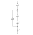
- FIG. 1 is a block diagram of a typical PI compensator used in controlling a motor.
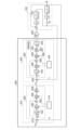
- FIG. 2 is a block diagram of a motor drive system including a controller circuit according to an embodiment.
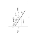
- FIG. 3 is a diagram for explaining automatic tuning of the first coefficient K1 of the first PI compensator of FIG.
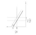
- FIG. 4 is a diagram for explaining the tuning of the third coefficient K3 of the first PI compensator of FIG.
- FIG. 5 is a block diagram of a conventional PI compensator.
- FIG. 6 is a block diagram showing an example of the configuration of the first PI compensator.
- FIG. 7 is a block diagram showing an example of the configuration of the second PI compensator.
- the controller circuit includes a major controller whose control variable is the rotation speed of the motor, and a minor controller whose control variable is the current flowing through the motor.
- the major controller includes a first PI (proportional-integral) compensator that generates an operation variable corresponding to a detection value of the control variable of the motor and an error in a command value of the control variable, and a first auto-tuning circuit that optimizes parameters of the first PI compensator.
- PI proportional-integral
- the first PI compensator includes a first integrator that integrates the error, a first coefficient circuit that multiplies the output of the first integrator by a first coefficient, a first adder that adds the output of the first coefficient circuit and the error, a second coefficient circuit that multiplies the output of the first adder by a second coefficient that is the reciprocal of the first coefficient, and a third coefficient circuit that multiplies the output of the second coefficient circuit by a third coefficient.
- the first automatic tuning circuit changes the first coefficient to adjust the error and the control amount to a value where the phase difference is 90 degrees
- the minor controller includes a second PI (proportional-integral) compensator that generates an operation amount according to the error between the detected value of the motor current and the current command value that is the output of the first PI compensator, and a second automatic tuning circuit that optimizes the parameters of the second PI compensator.
- PI proportional-integral
- the second PI compensator includes a second integrator that integrates the error, a fourth coefficient circuit that multiplies the output of the second integrator by a fourth coefficient, a second adder that adds the output of the fourth coefficient circuit and the error, a fifth coefficient circuit that multiplies the output of the second adder by a fifth coefficient that is the reciprocal of the fourth coefficient, and a sixth coefficient circuit that multiplies the output of the fifth coefficient circuit by a sixth coefficient.
- the second automatic tuning circuit changes the fourth coefficient to adjust the error and the control amount to a value where the phase difference is 90 degrees.
- the sixth coefficient is determined relatively to the third coefficient.
- the third coefficient does not affect the phase characteristics. Therefore, in the major loop, the phase difference can be optimized by changing the first coefficient, making automatic adjustment easy. Similarly, the sixth coefficient does not affect the phase characteristics. Therefore, in the minor loop, the phase difference can be optimized by changing the fourth coefficient, making automatic adjustment easy.
- the first and second coefficients are one parameter
- the fourth and fifth coefficients are one parameter, so it is sufficient to adjust four parameters. Therefore, compared to a configuration that requires six parameters, adjustment is simpler and memory capacity can be reduced.
- the first and fourth coefficients can be automatically adjusted using the zero-pole cancellation method, so in practice it can be simplified down to just two parameters, the third and sixth coefficients.
- the bandwidth characteristic ratio of the minor loop can be made faster than the overall response characteristics, and the number of adjustment parameters can be reduced to one while ensuring the stability of the system.
- a constant N (N is a real number greater than 1) may be configurable.
- the sixth coefficient is determined to be N times the third coefficient.
- a transfer function of a controlled object in which a current is input and a rotation speed is output, is expressed as 1/( ⁇ M ⁇ s+1) and a reference value of ⁇ M is ⁇ M0
- the first coefficient is 1/ ⁇ M0 ⁇
- the first automatic tuning circuit may change ⁇ with 1 as a reference.
- a transfer function of a controlled object whose input is a voltage applied to a motor and whose output is a current
- a transfer function of a controlled object is expressed as 1/( ⁇ C ⁇ s+1) and a reference value of ⁇ C is ⁇ C0
- the fourth coefficient is 1/ ⁇ C0 ⁇
- the second automatic tuning circuit may change ⁇ with 1 as a reference.
- a state in which component A is connected to component B includes not only cases in which component A and component B are directly physically connected, but also cases in which component A and component B are indirectly connected via other components that do not substantially affect their electrical connection state or impair the function or effect achieved by their connection.
- a state in which component C is provided between components A and B includes not only cases in which components A and C, or components B and C, are directly connected, but also cases in which they are indirectly connected via other components that do not substantially affect their electrical connection state or impair the function or effect achieved by their combination.
- the controlled object is a first-order lag element, and a PI compensator is used as the controller.
- the coefficients of the PI compensator are set so that the input/output characteristics of the system have the characteristics of a simple first-order low-pass filter.
- One method for setting the coefficients is the zero-pole cancellation method.
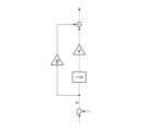
- Figure 1 is a block diagram of a typical PI compensator used in motor control. This compensator has three parameters. Specifically, there are the proportional gain Kp, the integral gain Ki, and the low-pass filter gain G.
- FIG. 2 is a block diagram of a motor drive system 100 including a controller circuit 400 according to an embodiment.
- the motor drive system 100 includes a motor 102, a controller circuit 400, and a drive circuit 300.
- Motor 102 is, for example, a three-phase or single-phase DC brushless motor.
- the controller circuit 400 feedback controls the electric signal (power, voltage, or current) supplied to the motor 102 so that the motor 102 rotates at a target rotation speed ⁇ ref .
- the controller circuit 400 may be implemented as a combination of a microcontroller (processor) and a software program, or as hardware logic such as a Field Programmable Gate Array (FPGA), or as an Application Specific Integrated Circuit (ASIC).
- processor microcontroller
- FPGA Field Programmable Gate Array
- ASIC Application Specific Integrated Circuit
- the drive circuit 300 supplies an electric signal corresponding to a manipulated variable u generated by the controller circuit 400 to the motor 102.
- the manipulated variable u is a voltage command
- the drive circuit 300 supplies a drive voltage V DRV based on the manipulated variable u to the motor 102.
- the controller circuit 400 and the drive circuit 300 may be separate ICs (Integrated Circuits) or may be a single IC integrated on the same semiconductor substrate.
- the configuration of the controller circuit 400 will be described.
- the controller circuit 400 has a multiple loop system including a major controller 410 and a minor controller 430.
- the major controller 410 controls a major loop (outer loop) with the rotation speed ⁇ of the motor 102 as a controlled variable.
- the major controller 410 generates a manipulated variable (current command value) iref so that an error (speed error) eSPD between a detected value ⁇ fb of the rotation speed ⁇ of the motor 102, which is a controlled variable, and a command value ⁇ ref of the rotation speed approaches zero.
- the current command value iref is supplied to the minor controller 430.
- the minor controller 430 controls a minor loop (inner loop) in which the current i flowing through the motor 102 is used as a control variable.
- the minor controller 430 generates a voltage command value Vref so that the error between the detection value iFB of the current i of the motor 102 and the current command value iref approaches zero.
- the voltage command value Vref corresponds to the operation variable u supplied to the drive circuit 300.
- the major controller 410 includes a first error detector 412, a first PI compensator 420, and a first automatic tuning circuit 414.
- the first error detector 412 is a subtractor, and generates an error (speed error) e SPD between a detected value ⁇ fb of the rotation speed ⁇ of the motor 102 and a command value ⁇ ref of the rotation speed.
- the first PI compensator 420 generates a current command value i ref so that the speed error e SPD approaches zero.
- the first PI compensator 420 includes a first integrator 422, a first adder 424, a first coefficient circuit 426, a second coefficient circuit 428, and a third coefficient circuit 429.
- the first integrator 422 integrates the speed error e SPD .
- the first coefficient circuit 426 multiplies the output of the first integrator 422 by a first coefficient K1.
- a first adder 424 adds the speed error e SPD to the output of a first coefficient circuit 426.
- a second coefficient circuit 428 multiplies the output of the first adder 424 by a second coefficient K2.
- the second coefficient K2 is the reciprocal of the first coefficient K1.
- the third coefficient circuit 429 multiplies the output of the second coefficient circuit 428 by a third coefficient K3.
- the output of the third coefficient circuit 429 becomes the current command value i ref .
- the first automatic tuning circuit 414 changes the first coefficient K1 to adjust it to a value that makes the phase difference between the speed error e SPD and the rotation speed ⁇ , which is the controlled variable, 90 degrees.
- the value of the second coefficient circuit 428 which is the inverse of the first coefficient K1, is also determined.
- the minor controller 430 includes a second error detector 432, a second PI compensator 440, and a second automatic tuning circuit 434.
- the second error detector 432 is a subtractor, and generates an error (current error) eC between the detection value i fb of the current i of the motor 102 and the current command value i ref .
- the second PI compensator 440 generates a voltage command value V ref so that the current error eC approaches zero.
- the second PI compensator 440 includes a second integrator 442, a third adder 444, a fourth coefficient circuit 446, a fifth coefficient circuit 448, and a sixth coefficient circuit 450.
- the second integrator 442 integrates the current error e C.
- the fourth coefficient circuit 446 multiplies the output of the second integrator 442 by a fourth coefficient K4.
- a third adder 444 adds the output of the fourth coefficient circuit 446 and the current error eC .
- a fifth coefficient circuit 448 multiplies the output of the third adder 444 by a fifth coefficient K5.
- the fifth coefficient K5 is the reciprocal of the fourth coefficient K4.
- the sixth coefficient circuit 450 multiplies the output of the fifth coefficient circuit 448 by a sixth coefficient K6.
- the output of the sixth coefficient circuit 450 becomes the voltage command value Vref .
- the sixth coefficient K6 is defined relatively to the third coefficient K3 used in the first PI compensator 420. Specifically, the value of the sixth coefficient K6 is set to N times the third coefficient K3. N is a real number greater than 1.
- the sixth coefficient circuit 450 includes a coefficient circuit 452, a multiplier 454, and a constant circuit 456.
- the coefficient circuit 462 multiplies the output of the fifth coefficient circuit 448 by the third coefficient K3.
- the constant circuit 456 is a memory that stores a predetermined value N.
- the multiplier 454 multiplies the output of the coefficient circuit 452 by the predetermined value N.
- the second automatic tuning circuit 434 changes the fourth coefficient K4 to adjust it to a value that makes the phase difference between the current error eC and the controlled variable, the current i, 90 degrees.
- the value of the fifth coefficient circuit 448 which is its inverse, is also determined.
- the transfer function with the coil current i as input and the rotation speed ⁇ as output is given by: K T / ⁇ D ⁇ ( ⁇ M ⁇ s+1) ⁇ where KT is the torque constant and D is the viscous damping coefficient (viscous friction coefficient).
- the first automatic tuning circuit 414 performs automatic tuning based on the zero-pole cancellation method. When the phase difference between the speed error e SPD and the rotation speed ⁇ , which is the controlled variable, becomes 90 degrees, the value of the first coefficient K1 becomes equal to ⁇ M.
- the transfer function with the drive voltage VDRV as an input and the coil current i as an output is given by 1/ ⁇ R ⁇ ( ⁇ C ⁇ s+1) ⁇
- the value of the fourth coefficient K4 becomes equal to ⁇ C .
- K E is the back electromotive force constant.
- FIG. 3 is a diagram explaining the automatic tuning of the first coefficient K1 of the first PI compensator 420 in FIG. 2.
- (i) shows the gain characteristic of the part including the integrator 422, the first coefficient circuit 426, and the first adder 424.
- the transfer function of this part is (K1/s+1), where K1/s is the integral term and 1 is the proportional term.
- K1/s is the integral term
- 1 is the proportional term.
- the controlled object is a first-order lag element having a transfer characteristic of 1/( ⁇ M s + 1), and has the gain characteristic of a low-pass filter having a cutoff frequency fc according to the time constant ⁇ M.
- the first coefficient K1 is optimized so that the frequency f at the intersection of the integral term K1/s and the proportional term 1 matches the cutoff frequency fc of the low-pass filter to be controlled.
- the gain characteristic of the entire system including the controlled object and the first PI compensator 420 becomes integral characteristic (iii).
- FIG. 4 is a diagram for explaining the tuning of the third coefficient K3 of the first PI compensator 420 in FIG. 2.
- the first coefficient circuit 426 and the second coefficient circuit 428 cancel each other out.
- the fourth coefficient K4 and the fifth coefficient K5 are optimized by the zero-pole cancellation method in the same manner as the first coefficient K1 and the second coefficient K2 of the first PI compensator 420.
- the third coefficient K3 of the first PI compensator 420 has already been determined.
- the sixth coefficient K6 is N times the third coefficient K3.
- the sixth coefficient K6 defines the cutoff frequency of the integral element of the minor loop.
- the parameter N defines how much wider the band of the minor loop is to be than the band of the major loop.
- the bandwidth characteristic ratio of the minor loop can be made greater than the characteristics of the overall response, and the number of adjustment parameters can be reduced to one while maintaining the stability of the system.
- First Advantage Fig. 5 is a block diagram of a conventional PI compensator.
- the integral gain Kp that gives a phase difference of 90 degrees changes. Therefore, if the integral gain Kp is once optimized so that the phase difference between input and output is 90 degrees, and then the proportional gain Ki is changed, the frequency characteristics of the entire system will deviate from those of the integrator, and it will be necessary to readjust the integral gain Kp. In other words, it is difficult to optimize two parameters simultaneously.
- the second coefficient K2 and the third coefficient K3 do not affect the phase characteristics. Therefore, even if the second coefficient K2 and the third coefficient K3 are changed after optimizing the first coefficient K1 so that the phase difference between the input and output is 90 degrees, the integral characteristics of the entire system are maintained, so there is no need to readjust the first coefficient K1.
- the first coefficient K1 and the second coefficient K2 are one parameter
- the fourth coefficient K4 and the fifth coefficient K5 are one parameter. Therefore, the parameters that need to be adjusted are only four: K1, K3, K4, and K6. Therefore, compared to the conventional configuration that requires six parameters, adjustment is simpler and memory capacity can be reduced.
- the first coefficient K1 and the fourth coefficient K4 can be automatically adjusted using the zero-pole cancellation method, so in practice, they can be simplified down to just two parameters, the third coefficient K3 and the sixth coefficient K6.
- the control target of the first PI compensator 420 is a first-order lag element, and its transfer function is expressed as follows: 1/( ⁇ M +1) where ⁇ M is a time constant.
- ⁇ M0 is determined for the time constant ⁇ M of the controlled object. This reference value ⁇ M0 may be determined as the average value of the time constants of several types of motors assumed to be controlled objects.
- the first automatic tuning circuit 414 changes the correction coefficient ⁇ based on 1, and adjusts it to a value that makes the phase difference between input and output 90 degrees.
- the control target of the second PI compensator 440 is a first-order lag element, and its transfer function is expressed as follows: 1/( ⁇ C +1) where ⁇ C is a time constant.
- a reference value ⁇ C0 is determined for the time constant ⁇ C of the controlled object. This reference value ⁇ C0 may be determined as the average value of the time constants of several types of motors assumed to be controlled objects.
- the second automatic tuning circuit 434 changes the correction coefficient ⁇ based on 1, and adjusts it to a value that makes the phase difference between input and output 90 degrees.
- a motor controller circuit comprising: a major controller that controls the rotation speed of the motor; a minor controller that controls the current flowing through the motor; Equipped with The major controller, a first PI (proportional-integral) compensator that generates an operation amount corresponding to an error between a detection value of a control amount of the motor and a command value of the control amount; a first auto-tuning circuit for optimizing parameters of the first PI compensator; Equipped with The first PI compensator is a first integrator for integrating the error; a first coefficient circuit that multiplies an output of the first integrator by a first coefficient; a first adder for adding an output of the first coefficient circuit and the error; a second coefficient circuit that multiplies the output of the first adder by a second coefficient that is the reciprocal of the first coefficient; a third coefficient circuit that multiplies an output of the second coefficient circuit by a third coefficient; Including, the first automatic tuning circuit changes the first coefficient to adjust it to a value such that a phase difference between
- (Item 2) 2. The controller circuit according to item 1, wherein a transfer function of a controlled object having the current as an input and the rotational speed as an output is expressed as 1/( ⁇ M ⁇ s+1), and when a reference value of ⁇ M is ⁇ M0 , the first coefficient is 1/ ⁇ M0 ⁇ , and the first automatic tuning circuit changes ⁇ with 1 as a reference.
- This disclosure relates to a motor controller circuit.
- Motor drive system 102 Motor 300 Drive circuit 400 Controller circuit 410 Major controller 412 First error detector 414 First automatic tuning circuit 420 First PI compensator 422 First integrator 424 First adder 426 First coefficient circuit 428 Second coefficient circuit 429 Third coefficient circuit 430 Minor controller 432 Second error detector 434 Second automatic tuning circuit 440 Second PI compensator 442 First integrator 444 Second adder 446 Fourth coefficient circuit 448 Fifth coefficient circuit 450 Sixth coefficient circuit
Landscapes
- Engineering & Computer Science (AREA)
- Power Engineering (AREA)
- Physics & Mathematics (AREA)
- General Physics & Mathematics (AREA)
- Automation & Control Theory (AREA)
- Artificial Intelligence (AREA)
- Health & Medical Sciences (AREA)
- Computer Vision & Pattern Recognition (AREA)
- Evolutionary Computation (AREA)
- Medical Informatics (AREA)
- Software Systems (AREA)
- Control Of Electric Motors In General (AREA)
- Control Of Ac Motors In General (AREA)
Priority Applications (2)
| Application Number | Priority Date | Filing Date | Title |
|---|---|---|---|
| JP2025510597A JPWO2024203648A1 (cg-RX-API-DMAC7.html) | 2023-03-31 | 2024-03-19 | |
| US19/336,764 US20260019017A1 (en) | 2023-03-31 | 2025-09-23 | Controller circuit for motor |
Applications Claiming Priority (2)
| Application Number | Priority Date | Filing Date | Title |
|---|---|---|---|
| JP2023058521 | 2023-03-31 | ||
| JP2023-058521 | 2023-03-31 |
Related Child Applications (1)
| Application Number | Title | Priority Date | Filing Date |
|---|---|---|---|
| US19/336,764 Continuation US20260019017A1 (en) | 2023-03-31 | 2025-09-23 | Controller circuit for motor |
Publications (1)
| Publication Number | Publication Date |
|---|---|
| WO2024203648A1 true WO2024203648A1 (ja) | 2024-10-03 |
Family
ID=92906096
Family Applications (1)
| Application Number | Title | Priority Date | Filing Date |
|---|---|---|---|
| PCT/JP2024/010831 Ceased WO2024203648A1 (ja) | 2023-03-31 | 2024-03-19 | モータのコントローラ回路 |
Country Status (3)
| Country | Link |
|---|---|
| US (1) | US20260019017A1 (cg-RX-API-DMAC7.html) |
| JP (1) | JPWO2024203648A1 (cg-RX-API-DMAC7.html) |
| WO (1) | WO2024203648A1 (cg-RX-API-DMAC7.html) |
Citations (5)
| Publication number | Priority date | Publication date | Assignee | Title |
|---|---|---|---|---|
| JP2012135087A (ja) * | 2010-12-20 | 2012-07-12 | Hitachi Ltd | 電動機制御装置 |
| JP2013132200A (ja) * | 2011-11-24 | 2013-07-04 | Panasonic Corp | モータ制御装置 |
| JP2019193532A (ja) * | 2018-04-27 | 2019-10-31 | ルネサスエレクトロニクス株式会社 | モータシステム、モータ制御装置およびモータの回転速度検出方法 |
| JP2020010569A (ja) * | 2018-07-12 | 2020-01-16 | 株式会社日立産機システム | 電力変換装置 |
| WO2022149206A1 (ja) * | 2021-01-06 | 2022-07-14 | 三菱電機株式会社 | 電力変換装置、モータ駆動装置及び冷凍サイクル適用機器 |
-
2024
- 2024-03-19 JP JP2025510597A patent/JPWO2024203648A1/ja active Pending
- 2024-03-19 WO PCT/JP2024/010831 patent/WO2024203648A1/ja not_active Ceased
-
2025
- 2025-09-23 US US19/336,764 patent/US20260019017A1/en active Pending
Patent Citations (5)
| Publication number | Priority date | Publication date | Assignee | Title |
|---|---|---|---|---|
| JP2012135087A (ja) * | 2010-12-20 | 2012-07-12 | Hitachi Ltd | 電動機制御装置 |
| JP2013132200A (ja) * | 2011-11-24 | 2013-07-04 | Panasonic Corp | モータ制御装置 |
| JP2019193532A (ja) * | 2018-04-27 | 2019-10-31 | ルネサスエレクトロニクス株式会社 | モータシステム、モータ制御装置およびモータの回転速度検出方法 |
| JP2020010569A (ja) * | 2018-07-12 | 2020-01-16 | 株式会社日立産機システム | 電力変換装置 |
| WO2022149206A1 (ja) * | 2021-01-06 | 2022-07-14 | 三菱電機株式会社 | 電力変換装置、モータ駆動装置及び冷凍サイクル適用機器 |
Also Published As
| Publication number | Publication date |
|---|---|
| US20260019017A1 (en) | 2026-01-15 |
| JPWO2024203648A1 (cg-RX-API-DMAC7.html) | 2024-10-03 |
Similar Documents
| Publication | Publication Date | Title |
|---|---|---|
| CN102969971B (zh) | 电动机控制装置 | |
| US9024566B2 (en) | Motor control device | |
| CN107645267B (zh) | 电动机系统 | |
| US9143073B2 (en) | Position control device for electric motor | |
| US20080061726A1 (en) | Control device for synchronous motor | |
| CN101103517B (zh) | 电动机控制装置 | |
| CN108646546B (zh) | 确定分数阶pid控制器参数的方法、装置、电力系统稳定器及电力系统 | |
| KR100967665B1 (ko) | 저속 영역에서의 전동기 속도 제어 시스템 및 속도 제어방법 | |
| CN115291569A (zh) | 伺服系统及其参数在线调节方法 | |
| CN109143849B (zh) | 伺服控制装置、伺服控制方法及伺服控制系统 | |
| JPWO2020075344A1 (ja) | フィードバック制御方法、およびフィードバック制御装置 | |
| WO2024203648A1 (ja) | モータのコントローラ回路 | |
| JP2007306753A (ja) | ノッチフィルタのパラメータ調整方法、プログラムおよびモータ制御装置 | |
| WO2024203647A1 (ja) | モータのコントローラ回路 | |
| Mallick et al. | Performance study of different model reference adaptive control techniques applied to a dc motor for speed control | |
| JPH086603A (ja) | サーボ系の調整方法及びそのサーボ制御装置 | |
| Mallick et al. | Comparative performance study of lyapunov based mrac technique and mrac augmented with pid controller for speed control of a dc motor | |
| JP5017984B2 (ja) | サーボ制御装置とその速度追従制御方法 | |
| JP2011078192A (ja) | 電動機の制御装置 | |
| CN109724327B (zh) | 控制空调器压缩机转速波动的方法 | |
| JP4760064B2 (ja) | 誘導電動機の制御方法 | |
| WO2016152074A1 (ja) | モータ駆動装置 | |
| CN111034010A (zh) | 同步控制装置 | |
| CN109713964B (zh) | 用于控制空调压缩机转速波动的方法 | |
| CN109724311B (zh) | 用于空调压缩机转速控制的方法 |
Legal Events
| Date | Code | Title | Description |
|---|---|---|---|
| 121 | Ep: the epo has been informed by wipo that ep was designated in this application |
Ref document number: 24779771 Country of ref document: EP Kind code of ref document: A1 |
|
| WWE | Wipo information: entry into national phase |
Ref document number: 2025510597 Country of ref document: JP |
|
| NENP | Non-entry into the national phase |
Ref country code: DE |
|
| 122 | Ep: pct application non-entry in european phase |
Ref document number: 24779771 Country of ref document: EP Kind code of ref document: A1 |