WO2024203304A1 - 反応熱利用システムおよび反応熱利用方法 - Google Patents
反応熱利用システムおよび反応熱利用方法 Download PDFInfo
- Publication number
- WO2024203304A1 WO2024203304A1 PCT/JP2024/009645 JP2024009645W WO2024203304A1 WO 2024203304 A1 WO2024203304 A1 WO 2024203304A1 JP 2024009645 W JP2024009645 W JP 2024009645W WO 2024203304 A1 WO2024203304 A1 WO 2024203304A1
- Authority
- WO
- WIPO (PCT)
- Prior art keywords
- reaction
- reactor
- heat storage
- fluid
- heat
- Prior art date
- Legal status (The legal status is an assumption and is not a legal conclusion. Google has not performed a legal analysis and makes no representation as to the accuracy of the status listed.)
- Ceased
Links
Images

















Classifications
-
- C—CHEMISTRY; METALLURGY
- C07—ORGANIC CHEMISTRY
- C07C—ACYCLIC OR CARBOCYCLIC COMPOUNDS
- C07C1/00—Preparation of hydrocarbons from one or more compounds, none of them being a hydrocarbon
- C07C1/02—Preparation of hydrocarbons from one or more compounds, none of them being a hydrocarbon from oxides of a carbon
- C07C1/04—Preparation of hydrocarbons from one or more compounds, none of them being a hydrocarbon from oxides of a carbon from carbon monoxide with hydrogen
-
- C—CHEMISTRY; METALLURGY
- C07—ORGANIC CHEMISTRY
- C07C—ACYCLIC OR CARBOCYCLIC COMPOUNDS
- C07C1/00—Preparation of hydrocarbons from one or more compounds, none of them being a hydrocarbon
- C07C1/20—Preparation of hydrocarbons from one or more compounds, none of them being a hydrocarbon starting from organic compounds containing only oxygen atoms as heteroatoms
- C07C1/22—Preparation of hydrocarbons from one or more compounds, none of them being a hydrocarbon starting from organic compounds containing only oxygen atoms as heteroatoms by reduction
-
- C—CHEMISTRY; METALLURGY
- C07—ORGANIC CHEMISTRY
- C07C—ACYCLIC OR CARBOCYCLIC COMPOUNDS
- C07C9/00—Aliphatic saturated hydrocarbons
- C07C9/02—Aliphatic saturated hydrocarbons with one to four carbon atoms
- C07C9/04—Methane
-
- F—MECHANICAL ENGINEERING; LIGHTING; HEATING; WEAPONS; BLASTING
- F28—HEAT EXCHANGE IN GENERAL
- F28D—HEAT-EXCHANGE APPARATUS, NOT PROVIDED FOR IN ANOTHER SUBCLASS, IN WHICH THE HEAT-EXCHANGE MEDIA DO NOT COME INTO DIRECT CONTACT
- F28D20/00—Heat storage plants or apparatus in general; Regenerative heat-exchange apparatus not covered by groups F28D17/00 or F28D19/00
- F28D20/02—Heat storage plants or apparatus in general; Regenerative heat-exchange apparatus not covered by groups F28D17/00 or F28D19/00 using latent heat
-
- Y—GENERAL TAGGING OF NEW TECHNOLOGICAL DEVELOPMENTS; GENERAL TAGGING OF CROSS-SECTIONAL TECHNOLOGIES SPANNING OVER SEVERAL SECTIONS OF THE IPC; TECHNICAL SUBJECTS COVERED BY FORMER USPC CROSS-REFERENCE ART COLLECTIONS [XRACs] AND DIGESTS
- Y02—TECHNOLOGIES OR APPLICATIONS FOR MITIGATION OR ADAPTATION AGAINST CLIMATE CHANGE
- Y02E—REDUCTION OF GREENHOUSE GAS [GHG] EMISSIONS, RELATED TO ENERGY GENERATION, TRANSMISSION OR DISTRIBUTION
- Y02E60/00—Enabling technologies; Technologies with a potential or indirect contribution to GHG emissions mitigation
- Y02E60/14—Thermal energy storage
Definitions
- the present invention relates to a reaction heat utilization system and a reaction heat utilization method, and in particular to a system and a method that are equipped with a reactor for carrying out a chemical reaction and utilize the reaction heat generated by the chemical reaction.
- Patent Document 1 discloses a methane production system equipped with a reactor for producing methane by a methanation reaction.
- Patent Document 1 proposes that the methanation reaction, which is an exothermic reaction, is advanced while the catalyst layer in the reactor is cooled with a heat medium (cooling water), and the reaction heat recovered by the heat medium is utilized as thermal energy for separating carbon dioxide from exhaust gases from industrial plants, etc.
- the object of the present invention is to solve the above problems by providing a reaction heat utilization system that can improve the temperature controllability within the reactor and can more efficiently utilize the reaction heat generated within the reactor.
- the reaction heat utilization system comprises: A reactor; and a supply unit that switchably supplies one of a first fluid and a second fluid different from the first fluid to the reactor; A discharge section that discharges a product fluid generated by a chemical reaction in the reactor from the reactor,
- the reactor is configured to accommodate a heat storage unit including a plurality of latent heat stores;
- Each of the multiple latent heat storage bodies is A core portion including a latent heat storage material;
- the first fluid includes a feed fluid that undergoes an exothermic reaction in the reactor, and/or the second fluid includes a feed fluid that undergoes an endothermic reaction in the reactor;
- the reactor is configured to alternate between a heat storage mode in which heat is stored in the heat storage section by supplying the first fluid from the supply section to the reactor, and a heat release mode in which heat is released from the heat storage section by supplying the second fluid
- the reaction heat utilization method comprises the steps of: a heat storage step of supplying a first fluid to a reactor housing a heat storage unit including a plurality of latent heat storage bodies to store heat in the heat storage unit; a heat dissipation step of discharging heat from the heat storage unit by supplying a second fluid different from the first fluid to the reactor,
- the method further includes a step of switching the fluid supplied to the reactor between the first fluid and the second fluid between the heat storage step and the heat release step,
- Each of the multiple latent heat storage bodies is A core portion including a latent heat storage material; A shell portion having a melting point higher than that of the latent heat storage material and enclosing the latent heat storage material therein;
- an exothermic reaction of the first fluid is caused in the reactor and a product fluid from the exothermic reaction is discharged from the reactor, and/or, in the heat release process, an endothermic reaction of the second fluid is caused in the reactor and a product
- the reaction heat utilization system and reaction heat utilization method of the present invention can improve the temperature controllability within the reactor and more efficiently utilize the reaction heat generated within the reactor.
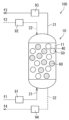
- FIG. 1 is a schematic cross-sectional view showing a part of a reaction heat utilization system according to an embodiment of the present invention.
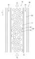
- FIG. 11 is a schematic cross-sectional view showing another example of a reaction heat utilization system.
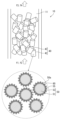
- 2A and 2B are a schematic diagram illustrating a heat storage unit in the reaction heat utilization system of FIG. 1 and an enlarged cross-sectional view illustrating a part of the heat storage unit.
- FIG. 2 is a schematic diagram for explaining the operation of the reaction heat utilization system of FIG. 1.
- 1 is a graph illustrating the temperature change in a reactor in a heat storage mode and a heat release mode.
- 2 is a schematic diagram showing another example of the heat storage unit in the reaction heat utilization system of FIG.
- FIG. 1 is a schematic cross-sectional view of a passive/active combined reactor.
- FIG. 1 is a schematic diagram illustrating the temperature distribution and the methane concentration distribution in a reactor when temperature control is performed by a passive/active combined method.
- FIG. 2 is a schematic diagram illustrating the temperature distribution and the methane concentration distribution in a reactor when temperature control is performed by an active method.
- FIG. 1 is a schematic cross-sectional view showing a batch operation type reaction heat utilization system.
- FIG. 11 is a schematic cross-sectional view for explaining the operation of the reaction heat utilization system of FIG. 10 during a first operation.
- FIG. 11 is a schematic cross-sectional view for explaining the operation of the reaction heat utilization system of FIG. 10 during a second operation.
- 11 is a flowchart showing a processing method using the reaction heat utilization system of FIG. 10.
- FIG. 11 is a schematic diagram illustrating a utilization pattern I of the reaction heat utilization system of FIG.
- FIG. 11 is a schematic diagram illustrating a utilization pattern II of the reaction heat utilization system of FIG. 10 .
- FIG. 11 is a schematic diagram illustrating a utilization pattern II of the reaction heat utilization system of FIG.
- FIG. 1 is a schematic diagram illustrating a reaction heat utilization system (utilization pattern II) that performs co-electrolysis and methanation reactions.
- FIG. 14 is a schematic diagram showing an application example of the reaction heat utilization system of FIG. 13.
- FIG. 14 is a schematic diagram showing another application example of the reaction heat utilization system of FIG. 13 .
- FIG. 14 is a schematic diagram showing yet another application example of the reaction heat utilization system of FIG. 13 .
- FIG. 1 is a schematic diagram showing an application example of a reaction heat utilization system for performing water electrolysis and methanation reactions.
- FIG. 1 is a schematic diagram showing a reaction heat utilization system (utilization pattern II) for performing a sorption-enhanced water-gas shift process.
- FIG. 2 is a schematic cross-sectional view of an experimental device used in an experiment to examine the thermal control effect.
- FIG. 1 is a graph showing the change in temperature over time in the reaction section in Test 1 using a catalyst-containing Al—Cu—Si heat storage pellet (sample A).
- FIG. 13 shows the change in temperature over time in the reaction zone in Test 2 using reference catalyst-containing Al 2 O 3 pellets (sample C1).
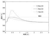
- FIG. 1 is a graph showing the change in temperature within the reaction section over time in Test 1 and Test 2.
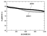
- FIG. 1 shows the change in CO2 conversion rate over time in Test 1 and Test 2.
- FIG. 13 is a graph showing the change in temperature over time in the reaction zone in Test 3 using a catalyst-containing Al—Si heat storage pellet (sample B) and Test 4 using a reference catalyst-containing Al 2 O 3 pellet (sample C2).
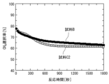
- FIG. 1 shows the change in CO2 conversion rate over time in Test 3 and Test 4.
- FIG. 1 shows the time course of CH4 selectivity in Test 3 and Test 4.
- FIG. 13 is a graph showing the change over time in temperature of the packed bed in Experimental Example 2.
- FIG. 13 is a diagram showing a heater temperature control program in Experimental Example 3.
- 13 is a graph showing the sample temperature and the heater temperature in Experimental Example 3.
- FIG. 27B is an enlarged view showing the area surrounded by the two-dot chain line in FIG. 27A.
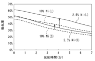
- 1 is a graph showing conversion rates during measurement periods m1 and m2 when samples H1 and H3 (Ni/MEPCM) were used.
- 1 is a graph showing conversion rates during measurement periods m1 and m2 when samples I1 and I3 (Co/MEPCM) were used.
- 1 is a graph showing the conversion rates during measurement periods m1 and m2 when samples J1 and J3 (Fe/MEPCM) were used.
- 10 is a schematic cross-sectional view illustrating an example of the arrangement of a latent heat storage material and a catalyst according to Modification 1.
- FIG. 10 is a schematic diagram illustrating the temperature distribution and the methane concentration distribution in the reaction section in the first modified example.
- FIG. 13 is a schematic cross-sectional view of the reaction section in Test 5.
- FIG. 13 is a schematic cross-sectional view of the reaction section in Test 6.
- FIG. 13 is a schematic cross-sectional view of the reaction section in Test 7.
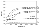
- FIG. 13 is a diagram showing the measurement results of the temperature inside the reaction section in Test 5 (uniform arrangement).
- FIG. 13 is a diagram showing the measurement results of the temperature inside the reaction section in Test 6 (two-stage inclined arrangement).
- FIG. 13 is a diagram showing the measurement results of the temperature inside the reaction section in Test 7 (three-stage inclined arrangement).
- FIG. 13 is a diagram showing the measurement results of temperature T25 in Tests 5 to 7.
- FIG. 13 is a schematic cross-sectional view of the reaction section in Test 5.
- FIG. 13 is a schematic cross-sectional view of the reaction section in Test 6.
- FIG. 13 is
- FIG. 13 is a diagram showing the measurement results of temperature T 50 in tests 5 to 7.
- FIG. 13 is a diagram showing the measurement results of temperature T 75 in tests 5 to 7.
- FIG. 13 is a diagram showing the measurement results of the temperature T 100 in Tests 5 to 7.
- 1 is an example of a SEM photograph of Ag/MEPCM in Experimental Example 5.
- 1 is an example of a SEM photograph of Ag/MEPCM (C/Ag/MEPCM) after carbon mixing in Experimental Example 5.
- 1 is an example of a SEM photograph of C/Ag/MEPCM in Experimental Example 5.
- 1 is an example of a SEM photograph of Ag/MEPCM after carbon combustion in Experimental Example 5.
- FIG. 13 is a diagram showing Ag mapping of Ag/MEPCM in Experimental Example 5.
- FIG. 13 is a diagram showing C mapping of Ag/MEPCM in Experimental Example 5.
- FIG. 13 is a diagram showing Ag mapping of C/Ag/MEPCM in Experimental Example 5.
- FIG. 13 is a diagram showing C mapping of C/Ag/MEPCM in Experimental Example 5.
- FIG. 13 shows Ag mapping of Ag/MEPCM after carbon combustion in Experimental Example 5.
- FIG. 13 shows C mapping of Ag/MEPCM after carbon combustion in Experimental Example 5.
- 1 shows the results of XRD analysis of MEPCM, Ag/MEPCM, and Ag/MEPCM after a combustion test in Experimental Example 5.
- FIG. 13 is a diagram showing the results of a combustion test of a sample (catalyst-containing latent heat storage material) according to the present embodiment in Experimental Example 5.
- FIG. 13 is a diagram showing the results of a combustion test of a sample (catalyst-containing latent heat storage medium) according to a comparative example in Experimental Example 5.
- a catalyst layer containing a methanation catalyst is usually housed in a reactor for carrying out a methanation reaction.
- a raw material fluid raw material gas
- a methanation reaction Sabatier reaction
- the methanation reaction is an exothermic reaction, and as the reaction proceeds, the temperature inside the reactor rises, making it difficult for the reaction to proceed.
- a temperature control mechanism is usually provided to control the temperature inside the reactor.
- a partition-type heat exchanger such as a plate type or a shell-and-tube type is used.
- a heat medium is circulated around the catalyst layer, and indirect heat exchange is performed between the heat medium and the catalyst layer via a heat transfer wall such as a metal plate.
- a heat transfer wall such as a metal plate.
- the methanation reaction can proceed while the catalyst layer is cooled by such indirect heat exchange.
- heat transfer distance can be on the order of centimeters or more, for example. This makes it difficult to efficiently cool the catalyst layer and recover the reaction heat.
- a reaction involving a large amount of reaction heat such as a methanation reaction
- large temperature distribution and localized high-temperature areas are likely to occur within the catalyst layer, and hot spots may cause catalyst deterioration.
- the inventors therefore conducted extensive research and discovered that by placing a latent heat storage material having a core portion containing a latent heat storage material and a shell portion enclosing the core portion in a reactor, the temperature in the reactor can be appropriately controlled and the reaction heat generated by an exothermic reaction can be efficiently recovered in the latent heat storage material. Furthermore, the inventors discovered that the reaction heat can be utilized more efficiently by alternating between a heat storage mode in which an exothermic reaction is carried out in the reactor and heat is stored in the latent heat storage material, and a heat release mode in which heat is released from the latent heat storage material. Based on this new finding, the inventors arrived at the present invention.
- the chemical reaction that takes place in the reactor may be an exothermic reaction other than a methanation reaction, or may be an endothermic reaction.
- the heat storage mode and the heat release mode By alternating between the heat storage mode and the heat release mode, and by causing an exothermic reaction in the heat storage mode and/or an endothermic reaction in the heat release mode, it is possible to increase the efficiency of heat utilization within the system.
- a chemical reaction (exothermic reaction, endothermic reaction) carried out in a reactor refers to a reaction in which, when a raw material fluid containing raw materials is supplied to the reactor, a chemical change in the raw material causes the production of a substance (product) different from the raw material.
- the product fluid containing the product obtained by the reaction is discharged from the reactor.
- "fluid” broadly includes anything that has fluidity, such as a liquid, gas, or a mixture of liquid and gas.
- the fluid may also be a fluid containing a solid, such as a suspension.
- FIG. 1A is a schematic cross-sectional view showing a part of a reaction heat utilization system 100 according to an embodiment of the present invention.
- the reaction heat utilization system 100 includes a reactor 10, a supply section 20 that supplies a fluid to the reactor 10, and a discharge section 30 that discharges the fluid from the reactor 10.
- the reactor 10 is configured to accommodate a heat storage section 40 including a plurality of latent heat storage bodies 50.
- the reactor 10 may be further configured to accommodate a catalyst 60.
- the reactor 10 has a flow path (internal flow path) through which a fluid flows, and the heat storage section 40 and catalyst 60 are accommodated in at least a portion of the flow path (hereinafter, the "reaction section") 11.
- the exothermic or endothermic reaction of the raw material fluid supplied to the reactor 10 mainly takes place in the reaction section 11.
- the supply unit 20 supplies a fluid to the internal flow path of the reactor 10.
- the supplied fluid passes through the reaction unit 11 and is discharged from the reactor 10.
- the supply unit 20 is configured to switchably supply one of the first fluid f1 and the second fluid f2 to the reactor 10.
- the first fluid f1 and the second fluid f2 pass through the same internal flow path in the reactor 10.
- the first fluid f1 and the second fluid f2 are different fluids.
- the first fluid f1 and/or the second fluid f2 may be a mixed fluid (e.g., a mixed gas) containing multiple types of fluid components.
- “the first fluid f1 and the second fluid f2 are different” means that at least one of the first fluid f1 and the second fluid f2 contains a fluid component that is not contained in the other, and some of the fluid components contained in the first fluid f1 and the second fluid f2 may be the same.
- the first fluid f1 may contain a first raw material fluid that generates an exothermic reaction in the reactor 10.
- the second fluid f2 may contain a second raw material fluid that generates an endothermic reaction in the reactor 10.
- the first fluid f1 may contain the first raw material fluid
- the second fluid f2 may contain the second raw material fluid.
- the supply unit 20 includes a first supply line 21 for supplying the first fluid f1, a second supply line 22 for supplying the second fluid f2, a switching unit 91 disposed on the first supply line 21, and a switching unit 92 disposed on the second supply line 22.
- the switching units e.g., valves
- 91 and 92 By the operation of the switching units (e.g., valves) 91 and 92, it is possible to switch between a state in which the first fluid f1 is supplied to the reactor 10 via the first supply line 21 and a state in which the second fluid f2 is supplied to the reactor 10 via the second supply line 22.
- a line in fluid communication with the reactor 10 is shown by a solid line
- a line not in fluid communication with the reactor 10 is shown by a dashed line.
- the discharge section 30 discharges the product fluid, which includes the product produced by the chemical reaction in the reactor 10, from the reactor 10.
- the discharge section 30 discharges the third fluid f3 when the first fluid f1 is supplied to the reactor 10, and discharges the fourth fluid f4 when the second fluid f2 is supplied to the reactor 10.
- the third fluid f3 may include a first product produced by an exothermic reaction of the first fluid f1 (first raw material fluid).
- the fourth fluid f4 may include a second product produced by an endothermic reaction of the second fluid f2 (second raw material fluid).
- the third fluid f3 may include the first product
- the fourth fluid f4 may include the second product.
- the discharge unit 30 includes a first discharge line 31 that discharges the third fluid f3, a second discharge line 32 that discharges the fourth fluid f4, a switching unit 93 arranged on the first discharge line 31, and a switching unit 94 arranged on the second discharge line 32.
- the switching units 93 and 94 e.g., valves
- the flow path of the discharged fluid can be switched so that the third fluid f3 is discharged from the reactor 10 via the first discharge line 31 when the first fluid f1 is supplied to the reactor 10, and the fourth fluid f4 is discharged from the reactor 10 via the second discharge line 32 when the second fluid f2 is supplied to the reactor 10.
- the number, positions, and structures of the supply lines, discharge lines, and switching parts connected to the reactor 10 are not limited to the illustrated example.
- two supply lines 21 and 22 are provided to supply fluids to the reactor 10, but a common supply line may be provided to supply the first and second fluids, for example.
- a common discharge line may be provided to discharge the third and fourth fluids, for example.
- the first fluid f1 and the second fluid f2 are both supplied to the reactor 10 from below and pass through the internal flow path in the same direction, but the structure of the supply part is not limited to this example.
- FIG. 1B and FIG.
- one of the first fluid f1 and the second fluid f2 may be supplied to the reactor 10 from above and the other from below, and the flow directions of the first fluid f1 and the second fluid f2 in the internal flow path may be opposite to each other.
- Heat storage section 40 2 is a schematic diagram illustrating the heat storage unit 40 and the catalyst 60 housed in the reaction unit 11, and an enlarged cross-sectional view showing a part of the heat storage unit.
- the reaction unit 11 may be filled with a heat storage molded body (hereinafter, "heat storage pellets") 41 including a plurality of latent heat storage bodies 50 as the heat storage unit 40.
- Each of the latent heat storage bodies 50 has a core portion 51 containing a latent heat storage material and a shell portion 53 in which the latent heat storage material is enclosed.
- the shell portion 53 is arranged so as to cover the surface of the approximately spherical core portion 51.
- the latent heat storage material is also called a phase change material (PCM).
- PCM phase change material
- the latent heat storage material utilizes the latent heat of solid-liquid phase change, and is capable of storing heat at a higher density than heat storage technologies that utilize sensible heat by storing heat through the latent heat of fusion and dissipating heat through the latent heat of solidification.
- the PCM can store and dissipate heat at a constant temperature (the melting point of the PCM), it can be used as a constant temperature heat source.
- the shell portion 53 has a higher melting point than the PCM of the core portion 51. By enclosing the core portion 51 in the shell portion 53, leakage of the PCM that melts and becomes liquid during heat storage can be prevented.
- the latent heat storage material 50 is a particle having a substantially spherical shape.
- the particle diameter of the latent heat storage material 50 is, for example, 1 ⁇ m or more, preferably 10 ⁇ m or more, and more preferably 20 ⁇ m or more.
- the particle diameter of the latent heat storage material 50 is, for example, 500 ⁇ m or less, preferably 200 ⁇ m or less, and more preferably 100 ⁇ m or less.
- the structure, shape, size, etc. of the latent heat storage material 50 are not limited to the example shown in the figure.
- the reaction section 11 may further contain a catalyst 60 that promotes an exothermic or endothermic reaction.
- a catalyst molded body (hereinafter, "catalyst pellets") 61 containing the catalyst 60 is disposed in the reaction section 11.
- the heat storage pellets 41 and the catalyst pellets 61 may be filled in a mixed state in the reaction section 11.
- the heat storage pellets 41 and the catalyst pellets 61 are arranged in a mixed state in the reaction section 11, but the method of arranging these pellets is not particularly limited.
- the porosity of the heat storage pellets 41 may be set so that part of the fluid can pass through the heat storage pellets 41 and come into contact with the latent heat storage body 50.
- the porosity of the heat storage pellets 41 may be, for example, about 0.3.
- the size of the heat storage pellets 41 may be, for example, in the range of 0.1 mm to 10 mm in average equivalent circle diameter.
- the reaction heat utilization system 100 is configured to alternate between a heat storage mode in which heat is stored in the heat storage section 40 by supplying a first fluid f1 to the reactor 10, and a heat release mode in which heat is released from the heat storage section 40 by supplying a second fluid f2 to the reactor 10.
- a line in fluid communication with the reactor 10 is indicated by a solid line
- a line not in fluid communication with the reactor 10 is indicated by a dashed line.
- “Alternating between heat storage mode and heat release mode” does not necessarily mean starting one mode immediately after the other mode ends, but also includes starting one mode after a period of time has elapsed since the other mode ended. For example, after one mode ends, the reactor 10 may be held in an insulated state for a certain period of time before starting the next mode.
- the first fluid f1 is supplied to the reactor 10, and an exothermic reaction of the first raw material fluid contained in the first fluid f1 occurs. At least a part of the reaction heat at this time is stored in the latent heat storage body 50 of the heat storage unit 40. In this way, it is possible to proceed with the exothermic reaction while recovering the reaction heat in the latent heat storage body 50.
- the heat storage mode may be terminated and switched to the heat dissipation mode.
- the second fluid f2 is supplied to the reactor 10, and an endothermic reaction of the second raw material fluid contained in the second fluid f2 occurs.
- the latent heat storage body 50 dissipates heat due to the endothermic reaction.
- the endothermic reaction is carried out using at least a part of the heat released from the latent heat storage body 50. In this way, it is possible to proceed with the endothermic reaction while receiving heat supply from the latent heat storage body 50.
- the reaction heat utilization system 100 may further include a temperature detection unit that detects the temperature inside the reactor 10, and a control unit.
- the control unit may be configured to operate the switching units 91 and 92 based on the temperature detected by the temperature detection unit, and to switch the fluid supplied to the reactor 10.
- an exothermic reaction may occur in the heat storage mode, and an endothermic reaction may occur in the heat release mode (utilization pattern I).
- the exothermic reaction and endothermic reaction may be selected as appropriate. It is preferable that the suitable temperature ranges of the exothermic reaction and the endothermic reaction are close to each other.
- a material having a melting point Tm according to the suitable temperature ranges of the exothermic reaction and the endothermic reaction may be used.
- a catalyst that promotes at least one of the exothermic reaction and the endothermic reaction, and preferably both, may be placed in the reactor.
- An exothermic reaction may be performed in the heat storage mode, and heat exchange between the heat medium and the latent heat storage material 50 may be performed in the heat dissipation mode (utilization pattern II).
- a low-temperature heat medium is supplied to the reactor 10 as the second fluid f2
- a high-temperature heat medium that is at a higher temperature than when it was supplied is discharged from the reactor 10 as the fourth fluid f4.
- an endothermic reaction may be performed in the heat dissipation mode, and heat exchange between the heat medium and the latent heat storage material 50 may be performed in the heat storage mode (utilization pattern III).
- a high-temperature heat medium is supplied to the reactor 10 as the first fluid f1
- a low-temperature heat medium that is at a lower temperature than when it was supplied is discharged from the reactor 10 as the third fluid f3.
- the latent heat storage body 50 having a PCM capable of storing heat at a high density is disposed in the reactor 10, so that the reaction heat can be controlled more efficiently.
- the latent heat storage body 50 is disposed in the internal flow path of the reactor 10, and the fluid supplied to the reactor 10 passes through the latent heat storage body 50 in direct contact with or in close proximity to the latent heat storage body 50.
- the latent heat storage body 50 can absorb the reaction heat in situ (at the heat generation position where an exothermic reaction or an exothermic phenomenon occurs) or release the heat in situ (at the heat absorption position where an endothermic reaction or an endothermic phenomenon occurs) to an endothermic reaction.
- the distance (heat transfer distance) between the heat generation position or heat absorption position and the PCM of the latent heat storage body 50 can be made smaller than that of conventional indirect heat exchange via a heat transfer wall. Therefore, the reaction heat can be more efficiently recovered to the latent heat storage body 50, and the heat from the latent heat storage body 50 can be more efficiently supplied to the heat absorption position.
- thermal control using the latent heat storage material 50 can reduce localized, sudden temperature changes (hot spots). This makes it possible to suppress catalyst deterioration caused by hot spots.
- the surface area of the latent heat storage material 50 becomes the heat transfer area, so the heat transfer area can be made larger than in the case of conventional indirect heat exchange without increasing the volume of the reactor.
- conventional indirect heat exchangers if an attempt is made to increase the heat transfer area, there is a risk that the size of the heat exchanger will increase.
- increasing the heat transfer area will increase the size of the reactor.
- the volume required for the heat exchange section can be made smaller than in the past, making it possible to miniaturize the system.
- the reaction heat utilization system 100 of this embodiment is configured to alternate between a heat storage mode and a heat release mode.
- the heat storage mode and the heat release mode are performed in the same reactor with the latent heat storage material 50 contained within the reactor 10 (without removing the latent heat storage material 50 from the reactor). This eliminates the need for heat transportation, and heat can be supplied from the latent heat storage material 50 and heat recovered to the latent heat storage material 50 with higher efficiency, thereby improving the heat utilization efficiency.
- Figure 4 is a schematic diagram illustrating the temperature change in a reactor when the heat storage mode and the heat release mode are repeated.
- the dashed line in Figure 4 shows an example of temperature change when exothermic and endothermic reactions are repeatedly performed in a reactor using conventional indirect heat exchange without placing a latent heat storage material in the reactor.
- the temperature inside the reactor rises due to the reaction heat of the exothermic reaction and remains constant or approximately constant for a certain period of time.
- the period P1 during which the exothermic reaction proceeds at an approximately constant temperature is called the "first period”
- the temperature during the first period P1 is called the "temperature reached during heat storage”.
- the temperature reached during heat storage is, for example, higher than the melting point Tm of the PCM. After this, the temperature inside the reactor rises above the temperature reached during heat storage.
- the heat storage mode may be terminated and switched to the heat dissipation mode.
- the temperature inside the reactor drops due to the endothermic reaction and remains approximately constant for a certain period of time.
- the period P2 during which the endothermic reaction proceeds at an approximately constant temperature is called the “second period”, and the temperature during the second period P2 is called the “temperature reached during heat dissipation”.
- the temperature reached during heat dissipation is, for example, lower than the melting point Tm of the PCM. After this, the temperature inside the reactor drops below the temperature reached during heat dissipation.
- the heat dissipation mode can be ended and switched to the heat storage mode.
- the PCM of the latent heat storage material 50 is considered to be maintained in a solid-liquid coexistence state (semi-molten state).
- a solid-liquid coexistence state the rate at which the PCM absorbs heat is balanced with the rate at which the PCM releases heat, making it possible to more effectively suppress local temperature fluctuations. For example, even if a localized and sudden temperature rise occurs, the solid part of the PCM can quickly absorb heat and mitigate the temperature rise.
- the temperature rise rate due to the exothermic reaction and the temperature fall rate due to the endothermic reaction can be suppressed lower than in the reference example in which the latent heat storage material is not used.
- the temperature continues to rise in the heat generation mode, and the temperature continues to fall in the heat dissipation mode.
- in each mode it is possible to proceed with the exothermic reaction or endothermic reaction while maintaining the temperature in the reactor at a suitable temperature (arrival temperature) for a certain period (first period P1, second period P2). Therefore, the yield can be increased compared to the reference example.
- the operating periods Ps and Pr from the start to the end (switching) of each mode can be lengthened, so that the durability of the system can be improved.
- the operating periods Ps and Pr are not particularly limited, but may be, for example, 10 to 30 minutes.
- the reaction heat utilization system 100 in this embodiment is used for various chemical reactions.
- a PCM having a melting point Tm corresponding to the temperature of the chemical reaction carried out in the reactor 10 can be used for the core portion 51 of the latent heat storage material 50 .
- the presence or absence of a catalyst 60, the type of catalyst 60, the flow rates of fluids f1 and f2, the filling amounts of the catalyst 60 and latent heat storage material 50, the form of the catalyst 60 and latent heat storage material 50 (such as the shape of pellets), and the temperature control method can also be appropriately selected.
- Suitable catalysts 60 vary depending on the chemical reaction, but may be, for example, metals having catalytic activity, more specifically, one or more metals selected from the group consisting of Group 4 elements such as Ti, Group 5 elements such as V, Group 6 elements such as Cr, Group 7 elements such as Mn, Group 8 elements such as Ru and Fe, Group 9 elements such as Rh and Co, Group 10 elements such as Ni, Pd, and Pt, Group 11 elements such as Cu and Ag, Group 12 elements such as Zn, and Group 13 elements such as In, and oxides and complexes thereof.
- Group 4 elements such as Ti
- Group 5 elements such as V
- Group 6 elements such as Cr
- Group 7 elements such as Mn
- Group 8 elements such as Ru and Fe
- Group 9 elements such as Rh and Co
- Group 10 elements such as Ni, Pd, and Pt
- Group 11 elements such as Cu and Ag
- Group 12 elements such as Zn
- Group 13 elements such as In, and oxides and complexes thereof.
- the structure of the heat storage unit 40 in this embodiment is not limited to the structure exemplified in Fig. 2.
- the heat storage unit 40 may be a molded body including a latent heat storage material 50 and a catalyst 60. Such a molded body is called a "catalyst-containing heat storage pellet.”
- FIG. 5 is a schematic diagram showing another example of the heat storage unit 40, and an enlarged cross-sectional view showing a part of the heat storage unit.
- the heat storage unit 40 has a catalyst-containing heat storage pellet 42 including a structure 50a in which a catalyst 60 is arranged on the surface of the latent heat storage body 50.
- the structure 50a in which the catalyst 60 is arranged on at least a part of the surface of the latent heat storage body 50 is called a "catalyst-containing latent heat storage body".
- the catalyst 60 may be supported or precipitated on at least a part of the surface of the shell portion 53 of the latent heat storage body 50.
- the coverage ratio of the catalyst 60 to the total surface area of the shell portion 53 may be, for example, 50 area% or more.
- each catalyst-containing latent heat storage body 50a has a latent heat storage body 50, a carrier layer 55 located on the surface of the shell portion 53 of the latent heat storage body 50, and a particulate catalyst 60 located on at least a portion of the surface of the carrier layer 55.
- the shape, amount of catalyst 60, and method of catalyst loading are not particularly limited.
- the shell portion 53 may also function as the carrier layer, and the catalyst may be located directly on the surface of the shell portion 53.
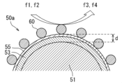
- FIG. 6 is an enlarged cross-sectional view showing a part of the catalyst-containing latent heat storage body 50a.
- the heat transfer distance d between the heat absorption position where the heat absorption reaction of the second fluid f2 (or heat absorption phenomenon from the heat medium) occurs and the PCM of the core part 51 can be further reduced in the heat dissipation mode, so that heat can be efficiently supplied from the PCM to the heat absorption position.
- the heat transfer distance d corresponds to the total thickness of the shell part 53 and the carrier layer 55 that cover the PCM.
- the distance (heat transfer distance d) between the catalyst 60 and the PCM in each catalyst-containing latent heat storage body 50a may be, for example, on the order of micrometers (e.g., less than 1 mm).
- catalyst-containing latent heat storage material 50a When using catalyst-containing latent heat storage material 50a, it is not necessary to fill reactor 10 with separate catalyst pellets.
- catalyst pellets the catalyst particles located near the pellet surface mainly function as catalysts, and the catalyst particles in the center of the pellet are less likely to come into contact with the raw material fluid, and it is possible that they may not be able to fully exert their catalytic function.
- catalyst-containing latent heat storage material 50a all of the catalyst particles on the surface of the latent heat storage material are more likely to come into contact with the raw material fluid and easily exert their catalytic function. Therefore, when catalyst-containing heat storage pellets are used, the amount of catalyst to be filled can be reduced compared to when heat storage pellets and catalyst pellets are used. By reducing the volume of the catalyst, the amount of catalyst to be filled in the latent heat storage material can be increased, making it possible to improve the effect of thermal control.
- the catalyst particles are located on the surface of the latent heat storage material, but the catalyst-containing heat storage pellet 42 only needs to contain the catalyst particles and the latent heat storage material, and for example, the catalyst particles and the latent heat storage material may be randomly mixed within the pellet.
- FIG. 7 is a diagram showing a schematic diagram of yet another example of the heat storage unit 40, showing a perspective view, a cross-sectional view, and an enlarged cross-sectional view of the heat storage pellet 41 near the surface of the heat storage pellet 41.
- a catalyst 60 may be arranged on at least a part of the surface of the heat storage pellet 41 including the latent heat storage body 50.
- the catalyst 60 may be supported or precipitated on the surface of the heat storage pellet 41. This makes it possible to reduce the distance (heat transfer distance) d between the catalyst 60 and the PCM of the latent heat storage body 50 compared to the case where a catalyst pellet is arranged (FIG. 2).
- the coverage ratio of the catalyst 60 to the total surface area of the heat storage pellet 41 can be, for example, 50 area % or more.
- catalyst particles may be further arranged on the surface of the catalyst-containing heat storage pellet 42 shown in FIG. 5.
- each pellet constituting the heat storage unit or catalyst is shown as being cylindrical in shape, but the shape of the pellet is not particularly limited, and it is preferable that the pellet maintains the necessary strength, has little pressure loss in the fluid, and efficiently exchanges heat with the fluid and reacts with the fluid.
- Pellet shapes of various known shapes can be used.
- the shape of the pellet may be, for example, spherical, elliptical, cylindrical, rectangular, cubic, honeycomb, hollow cylindrical, hollow prismatic, granular, crushed, etc.
- the heat storage unit may have a structure in which catalyst particles are arranged on the surface of a honeycomb-shaped heat storage pellet.
- multiple pellets of different shapes, sizes, or structures may be used.
- the latent heat storage body may not be formed as a molded body, and the latent heat storage body may be directly filled or placed in the reaction unit.
- a structure in which the latent heat storage body (and catalyst) is fixed to the surface of a support (e.g., a honeycomb-shaped support) made of another material may be formed, and placed in the reaction unit.
- a medium-high temperature PCM having a melting point Tm of, for example, 100°C or more may be used.
- the medium-high temperature PCM include sugar alcohols, molten salts, metals, and alloys.
- the metal and alloy PCM include an element selected from the group consisting of Al, Mg, Si, Ti, Fe, Ni, Cu, Zn, Sn, Sb, Ga, In, Bi, Pb, and Cd, or an alloy or compound containing these as a main component.
- molten salts having a melting point in a suitable temperature range for example, carbonate compounds of alkali metals, alkaline earth metals, hydroxides, (sub)nitrates, fluorides, chlorides, and other halides, or composites thereof, may be used.
- a low-temperature PCM having a relatively low melting point Tm for example, 100°C or less
- Tm melting point
- the low-temperature PCM include paraffin, fatty acid, and inorganic hydrated salts.
- the shell portion 53 includes a material having a higher melting point than the PCM in the core portion 51. It is preferable that the components of the shell portion 53 do not undergo chemical reactions in the operating temperature range.
- the core portion 51 includes a medium to high temperature PCM such as a metal or alloy PCM
- ceramics may be used as the material for the shell portion 53. Examples of ceramics include at least one selected from the group consisting of alumina, aluminum nitride, zirconia, silicon nitride, and silicon carbide, or a composite thereof.
- the material for the shell portion may be a resin material such as a hydrophobic resin.
- the average particle diameter of the core portion 51 may be, for example, 10 ⁇ m or more and 200 ⁇ m or less.
- the "average particle diameter" is a value measured with a laser diffraction particle size distribution meter (e.g., HORIBA LA-920). More specifically, the volume distribution of the particle group is measured with a laser diffraction particle size distribution meter, and the cumulative 50 volume % diameter value (D50) is regarded as the average particle diameter.
- the thickness of the shell portion 53 may be, for example, 200 nm or more and 5 ⁇ m or less.
- the shell portion 53 preferably covers the entire surface of the core portion 51, but may have a minute gap (opening) that exposes the surface of the core portion 51.
- the core section 51 is preferably made of a PCM containing an alloy or metal as the main component.
- "Main component” means that the proportion of the entire core section 51 is 50% by mass or more.
- Metal or alloy-based PCMs have higher thermal conductivity than other PCMs such as organic substances, inorganic hydrates, and molten salts, and can further increase the heat exchange rate.
- metal or alloy-based PCMs have a high melting point Tm, so they can be suitably used for chemical reactions with relatively high reaction temperatures.
- the temperature of the reactor (reaction section) during operation in the heat storage mode and heat release mode may be, for example, 150°C or higher.
- the PCM of the core portion 51 may contain a metal or alloy as a main component, and the shell portion 53 may contain a ceramic as a main component.
- the metal contained in the core portion 51 and the metal contained in the shell portion 53 may be the same or different.
- a latent heat storage body 50 it is possible to easily produce molded bodies of various shapes. For example, by mixing the latent heat storage body 50 with a binder material such as glass frit or alumina, molding, and firing it, it is possible to produce a molded body having a desired size and shape (particulate, honeycomb, ring, cylindrical, etc.). By using a molded body, it is possible to fill a predetermined amount of latent heat storage body while securing a flow path for the fluid flowing into the reactor.
- the component (PCM) of the core part 51 may be an element selected from the group consisting of Al, Mg, Zn, Sb, Pb, and Cd, or an alloy or compound containing these as main components.
- the melting point of the PCM may be, for example, within a range of 300 to 700°C.
- PCMs include PCMs containing Al, Al-Si alloys, Al-Cu-Si alloys, Zn-Al alloys, etc.
- the component of the shell part 53 may be one or more selected from the group consisting of elements different from the components of the core part 51, alloys and inorganic compounds containing the elements, and mixtures thereof. It is preferable that the shell part 53 does not chemically react with the core part 51 in the temperature range of the chemical reaction carried out in the reactor.
- the manufacturing method of the latent heat storage material 50 is not particularly limited.
- a metal coating may be formed on the surface of the latent heat storage material by electrolytic plating.
- the latent heat storage material 50 may be formed by covering a core part containing a metal/alloy-based PCM with an oxide coating of the composition elements contained in the core part. In this process, the surface of the core part is subjected to a chemical conversion coating treatment to form a primary coating, and then the primary coating is heat-treated to form an oxide coating as a secondary coating on the surface of the core part.
- the chemical conversion coating treatment may be any of the sol-gel method, anodizing treatment, alkali-chromium hydrochloride method, boehmite method, chromium hydrochloride method, phosphoric acid-chromium hydrochloride method, zinc phosphate method, and non-chromate chemical conversion coating treatment method.
- anodizing treatment alkali-chromium hydrochloride method, boehmite method, chromium hydrochloride method, phosphoric acid-chromium hydrochloride method, zinc phosphate method, and non-chromate chemical conversion coating treatment method.
- PCT/JP2022/033596 by the present applicant, a core raw material particle made of a PCM containing a metal or alloy and one or more child particles different from the components of the core particle are prepared, and the core raw material particle and the child particle are collided by an impact method in a high-speed air stream to perform hybridization in which the child particle is fixed to the surface of the core raw material particle, thereby forming the latent heat storage body 50.
- the entire disclosure of JP 2019-173017 A and International Application No. PCT/JP2022/033596 by the present applicant is incorporated herein by reference.
- At least a part of the shell portion has a particle shape derived from the child particles. In this respect, it differs from latent heat storage particles manufactured by, for example, a wet method.
- At least a part of the shell portion can be an aggregate of particles, for example an aggregate of child particles used during manufacturing.
- "At least a part of the shell portion has a particle shape" means that at least 10 particles (some of which may be joined to other particles) are confirmed when observed at a magnification of 10,000 times with a scanning electron microscope.
- the area of the shell portion other than the particle-shaped area can be, for example, a porous or dense solid layer formed by melting and agglomerating the child particles.
- Temperature control method A temperature control method in the reaction heat utilization system of this embodiment will be described. In this embodiment, it is possible to perform temperature control substantially only by the latent heat storage material 50 (without providing a separate heat exchanger). This type of control method is called a "passive method.” Alternatively, a “passive/active combined method" can be performed in which temperature control by the latent heat storage material 50 and heat control by a heat exchanger are used in combination. In the following description, for comparison, a conventional control method using only a heat exchanger without using a latent heat storage material is called an "active method."
- the part (reaction section) 11 in the reactor 10 in which the heat storage section 40 is housed may be insulated.
- a heat insulating material may be disposed around the reactor 10 or around the internal flow path including the reaction section 11. This allows the reaction heat from the exothermic reaction to be stored in the latent heat storage material 50 more efficiently, thereby further improving the heat utilization efficiency.
- Fig. 8 is a cross-sectional view showing a part of a reaction heat utilization system when performing temperature control of the passive/active combined method.
- the reaction heat utilization system may further include a heat exchanger 80 arranged adjacent to the part of the reactor 10 where the heat storage unit 40 is accommodated.
- the heat exchanger 80 is arranged, for example, on the outer periphery of the reaction section 11 in the reactor 10, and has a heat medium flow path 83 through which the heat medium 81 flows.
- the reaction section 11 and the heat medium flow path 83 are separated by a heat transfer wall 12 with high thermal conductivity.
- the fluid f1 containing the raw material fluid passes through the reaction section 11 in the x direction (downward in FIG. 8).
- heat exchange can be performed between the heat medium 81 in the heat medium flow path 83 and the latent heat storage material 50 and catalyst 60 in the reaction section 11 through the heat transfer wall 12. This makes it possible to suppress the temperature rise in the reaction section 11.
- the heat exchange between the heat medium 81 flowing in the heat medium flow path 83 and the latent heat storage material 50 and catalyst 60 makes it possible to suppress the temperature drop in the reaction section 11.
- the controllability of the temperature inside the reactor 10 can be further improved.
- the PCM in the latent heat storage material 50 rapidly repeats heat storage and release, making it easier to maintain a solid-liquid coexistence state (semi-molten state). This makes it possible to maintain the inside of the reactor 10 at an appropriate target temperature for a longer period of time, further improving the yield.
- the type, flow rate, etc. of the heat medium 81 can be appropriately controlled to maintain an appropriate temperature (so that periods P1 and P2 are longer in the example shown in Figure 4).
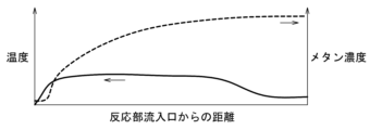
- FIG. 9A is a schematic diagram illustrating the temperature distribution and the concentration distribution of the product (here, methane) in the reactor 10 when the methanation reaction proceeds while performing temperature control using the passive/active combined system.
- the vertical axis is the temperature and the methane concentration
- the horizontal axis is the distance along the x direction from the inlet (upstream end) of the reaction section 11.
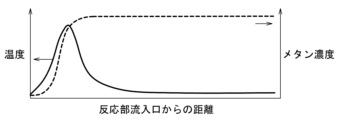
- FIG. 9B shows the temperature distribution and the methane concentration distribution when the temperature is controlled using an active system using only a heat exchanger without filling the reactor with a latent heat storage material. As can be seen from FIG.
- a localized exothermic reaction occurs near the inlet of the reaction section 11, causing a sudden rise in temperature and generating a hot spot.
- the passive/active combined system suppresses the generation of hot spots, and the methanation reaction can be generated at a relatively low temperature throughout the reaction section 11. Therefore, catalyst deterioration can be further suppressed.
- Fig. 10 is a schematic cross-sectional view showing a modified reaction heat utilization system 101.
- the reaction heat utilization system 101 is configured to perform a batch operation.
- the reaction heat utilization system 101 includes a plurality of reactors 10 including a first reactor 10A and a second reactor 10B. Although two reactors 10 are shown in Fig. 10, the number of reactors 10 may be three or more.
- Each of the first reactor 10A and the second reactor 10B has a configuration similar to that of the reactor 10 described above.
- Each of the first reactor 10A and the second reactor 10B has a reaction section 11 that contains a plurality of latent heat storage bodies 50.
- the latent heat storage bodies 50 contained in the first reactor 10A and the second reactor 10B may be substantially the same (i.e., the material, size, structure, forming method, etc. are the same) and may have the same filling rate.
- the reaction sections 11 of the first reactor 10A and the second reactor 10B may contain the same catalyst 60 at the same filling rate.
- the first reactor 10A and the second reactor 10B are filled with a plurality of catalyst-containing heat storage pellets 42 containing the latent heat storage body 50 and the catalyst 60 as the heat storage section 40.
- the structure of the heat storage section 40 is not limited and may be the structure described with reference to FIG. 2 and FIG. 7.
- the supply section 20 includes first supply lines 21A, 21B for supplying the first fluid f1, and second supply lines 22A, 22B for supplying the second fluid.
- the first supply line 21A supplies the first fluid f1 from a supply source (first supply source) 23 of the first fluid f1 to the first reactor 10A.
- the first supply line 21B supplies the first fluid f1 from the first supply source 23 to the second reactor 10B.
- the second supply lines 22A, 22B supply the second fluid f2 from a supply source (second supply source) 24 of the second fluid f2 to the first reactor 10A and the second reactor 10B, respectively.
- the supply unit 20 may further include a first fluid line 25 that transports the first fluid f1 from the first supply source 23, a second fluid line that transports the second fluid f2 from the second supply source 24, and switching units 91, 92.
- the switching unit 91 is connected to the first fluid line 25, the first supply line 21A, and the first supply line 21B, and switches the flow path of the first fluid f1.
- the switching unit 92 is connected to the second fluid line 26, the second supply line 22A, and the second supply line 22B, and switches the flow path of the second fluid f2.
- the switching units 91, 92 are, for example, three-way valves.
- the supply unit 20 is configured to be switchable between a first communication state in which the first fluid line 25 is fluidly connected to the first reactor 10A and the second fluid line 26 is fluidly connected to the second reactor 10B, and a second communication state in which the first fluid line 25 is fluidly connected to the second reactor 10B and the second fluid line 26 is fluidly connected to the first reactor 10A, by the operation of the switching units 91 and 92.
- the discharge section 30 includes first discharge lines 31A, 31B for discharging the third fluid f3 and second discharge lines 32A, 32B for discharging the fourth fluid f4.
- the first discharge line 31A discharges the third fluid f3 from the first reactor 10A
- the first discharge line 31B discharges the third fluid f3 from the second reactor 10B.
- the second discharge lines 32A, 32B discharge the fourth fluid f4 from the first reactor 10A and the second reactor 10B, respectively.
- the discharge section 30 may further include a first transport line 33 arranged to transport the third fluid f3 to the outside of another device or system, a second transport line 34 to transport the fourth fluid f4 to the outside of another device or system, and switching sections (e.g., three-way valves) 93, 94.
- the switching section 93 is connected to the first transport line 33, the first discharge line 31A, and the first discharge line 31B, and switches the flow path of the third fluid f3.
- the switching section 94 is connected to the second transport line 34, the second discharge line 32A, and the second discharge line 32B, and switches the flow path of the fourth fluid f4.
- the first transport line 33 in the first communication state, is fluidly connected to the first reactor 10A, and the second transport line 34 is fluidly connected to the second reactor 10B.
- the second transport line 34 in the second communication state, is fluidly connected to the first reactor 10A, and the first transport line 33 is fluidly connected to the second reactor 10B.
- the second reactor 10B operates in a heat dissipation mode when the first reactor 10A is in a heat storage mode, and the second reactor 10B operates in a heat storage mode when the first reactor 10A is in a heat dissipation mode.
- An operation in which the first reactor 10A operates in a heat storage mode and the second reactor 10B operates in a heat dissipation mode is called a "first operation”
- an operation in which the first reactor 10A operates in a heat dissipation mode and the second reactor 10B operates in a heat storage mode is called a "second operation”.
- the first operation and the second operation are performed alternately.
- Such an operation method is called a "batch operation”.
- the first operation and the second operation can be switched by switching the fluid supplied to each reactor.
- a batch operation it is possible to continuously perform an exothermic reaction and/or an endothermic reaction while replacing the reactor (semi-continuous process). Therefore, a semi-continuous process can be realized with a fixed bed.
- FIG. 11A is a schematic cross-sectional view for explaining the operation of the reaction heat utilization system 101 during a first operation
- FIG. 11B is a schematic cross-sectional view for explaining the operation of the reaction heat utilization system 101 during a second operation.
- FIG. 11C is a flowchart showing a processing method (heat utilization method) using the reaction heat utilization system 101.
- the first reactor 10A is supplied with the first fluid f1 through the first supply line 21A, and the second reactor 10B is supplied with the second fluid f2 through the second supply line 22B (first communication state).
- the first reactor 10A operates in the heat storage mode
- the second reactor 10B operates in the heat release mode (step S1).
- an exothermic reaction of the first fluid f1 occurs to generate a third fluid f3, and the generated third fluid f3 is sent to the first transport line 33 through the first discharge line 31A.
- Heat is stored in the heat storage section 40 (latent heat storage body 50) in the first reactor 10A by the reaction heat generated by the exothermic reaction.
- the temperature in the first reactor 10A may be monitored by a temperature detector, and it may be determined whether the temperature in the first reactor 10A exceeds a set first temperature T1 (see FIG. 4) (step S2). Additionally or alternatively, it may be determined whether the temperature in the second reactor 10B is below a set second temperature T2 (see FIG. 4).
- a first operation switching operation is performed (step S3).
- the switching unit 91 switches the supply destination of the first fluid f1 from the first reactor 10A to the second reactor 10B, and the switching unit 92 switches the supply destination of the second fluid f2 to the first reactor 10A (second communication state).
- the supply of the first fluid f1 and the second fluid f2 may be temporarily stopped before switching the supply destination.
- the switching unit 93 switches the flow path of the fluid discharged from the first reactor 10A from the first discharge line 31A to the second discharge line 32A
- the switching unit 94 switches the flow path of the fluid discharged from the second reactor 10B from the second discharge line 32B to the first discharge line 31B. This starts the second operation.
- the first reactor 10A is supplied with the second fluid f2 via the second supply line 22A, and the second reactor 10B is supplied with the first fluid f1 via the first supply line 21B.
- the first reactor 10A operates in the heat dissipation mode, and the second reactor 10B operates in the heat storage mode (step S4).
- an endothermic reaction of the second fluid f2 occurs using the heat stored in the heat storage section 40 during the first operation.
- the fourth fluid f4 generated by the endothermic reaction is discharged via the second discharge line 32A.
- an exothermic reaction of the first fluid f1 occurs, generating a third fluid f3, and the generated third fluid f3 is discharged via the first discharge line 31B.
- the heat of reaction generated by the exothermic reaction is stored in the heat storage section 40 (latent heat storage body 50) in the second reactor 10B.
- the temperature in the second reactor 10B may be monitored by a temperature detector to determine whether the temperature in the second reactor 10B exceeds the set first temperature T1 (see FIG. 4) (step S5). Additionally or alternatively, it may be determined whether the temperature in the first reactor 10A is below the second temperature T2 (see FIG. 4).
- a second operation switching operation is performed (step S7).
- the switching units 91 to 94 switch each line to the state during the first operation (first communication state). After this, the first operation is started again. In this way, the first operation and the second operation can be alternately repeated with the operation switching operation in between.
- step S6 a decision may be made as to whether to terminate the process at that point.
- step S8 the supply of the first fluid f1 and the second fluid f2 to the reactor is stopped by the operation of the switching unit of each supply line. This makes it possible to terminate the process, for example, for the purpose of system maintenance or when the supply of the raw material fluid is changed or stopped.
- the decision in step S6 is made after the second operation is completed, but it may be made at any time, for example, after the first operation is completed.
- the batch-type reaction heat utilization system 101 can also be utilized in the patterns I to III shown in Table 1.
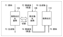
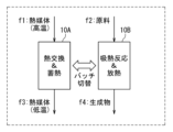
- Figures 12A to 12C are schematic diagrams illustrating utilization patterns I to III of the reaction heat utilization system 101, respectively. These figures explain the operation of the batch-type reaction heat utilization system 101 during the first operation as an example. Below, specific examples of each utilization pattern will be explained with reference to the drawings. Note that these specific examples can also be applied to reaction heat utilization systems other than the batch-type.
- ⁇ Utilization pattern I (direct collection type) As shown in FIG. 12A, in utilization pattern I, an exothermic reaction of a first fluid f1 and heat storage in a heat storage section are carried out in a reactor operating in a heat storage mode (here, the first reactor 10A), and an endothermic reaction of a second fluid f2 and heat release from the heat storage section are carried out in a reactor operating in a heat release mode (here, the second reactor 10B).
- a methanation reaction (Sabatier reaction) may be performed as an exothermic reaction, and an ammonia decomposition reaction may be performed as an endothermic reaction.
- a catalyst for example, a catalyst having a function of promoting both the methanation reaction and the ammonia decomposition reaction, such as a ruthenium (Ru) catalyst, may be used.
- the reaction formulas and reaction temperatures of each reaction are shown in Table 2.
- Such a reaction heat utilization system may be used, for example, for converting ammonia gas transported from overseas into methane gas for civilian use.
- the fourth fluid f4 which is a heat medium in a high temperature state, may be sent to another reactor or reaction device that requires heat.
- the fourth fluid f4 is supplied to the reaction device 110 as a raw material fluid.
- a fifth fluid f5 (raw material fluid) may be further supplied to the reaction device 110.
- the fourth fluid f4 and the fifth fluid f5 supplied to the reaction device 110 cause, for example, an endothermic reaction.
- Another catalyst that promotes the endothermic reaction may be contained in the reaction device 110.
- the product fluid generated by the endothermic reaction is discharged from the reaction device 110 as a sixth fluid f6. According to this pattern, since the exothermic reaction and the endothermic reaction do not need to be performed in the same reactor, catalysts suitable for each reaction can be selected independently. Therefore, the applicable reaction system can be expanded.
- a methanation reaction may be performed as an exothermic reaction, and electrolysis (co-electrolysis) of water and carbon dioxide may be performed in the reactor 110.
- electrolysis co-electrolysis
- the specific system configuration, reaction formula, etc. will be described later (see FIG. 13).
- ⁇ Utilization pattern III (indirect recovery type) As shown in FIG. 12C, in the utilization pattern III, a high-temperature heat medium is supplied as a first fluid f1 to a reactor (here, the first reactor 10A) operating in the heat storage mode. As a result, heat exchange between the heat medium and the heat storage section and the catalyst is performed, and heat is stored in the heat storage section (heat storage mode). The heat medium, which has become lower in temperature than when it was supplied due to the heat exchange, is discharged from the first reactor 10A as a third fluid f3.
- a reactor here, the second reactor 10B operating in the heat dissipation mode
- an endothermic reaction of the second fluid f2 and heat dissipation from the heat storage section are performed.
- a heat generation phenomenon such as adsorption (or occlusion) may be caused.
- a heat medium that has been brought to a high temperature state by exhaust heat from an electric furnace or the like may be supplied to one of the reactors as the first fluid f1, and the exhaust heat may be recovered in the heat storage section.
- the heat recovered in the heat storage section can be used for an endothermic reaction in the heat release mode.
- FIG. 13 is a schematic diagram illustrating a reaction heat utilization system 200 that performs co-electrolysis and methanation.
- the reaction heat utilization system 200 includes a first reactor 10A, a second reactor 10B, and a reaction device 110.
- Each of the first reactor 10A and the second reactor 10B contains a latent heat storage material and a catalyst.
- the PCM of the latent heat storage material for example, a Zn-Al-based PCM with a melting point Tm of about 380°C, or an Al-Si-based PCM with a melting point Tm of 577°C, is used.
- the catalyst for example, a Ni catalyst or a Ru catalyst is used.
- reaction heat utilization system 200 a methanation reaction (CO methanation reaction) and heat storage in the heat storage section are carried out in one reactor (first reactor 10A in FIG. 13), while heat exchange and heat release from the heat storage section are carried out in the other reactor (second reactor 10B in FIG. 13).
- reaction device 110 electrolysis (co-electrolysis) of water and carbon dioxide is carried out as an endothermic reaction.
- the reaction device 110 may be, for example, a solid oxide electrolysis cell (SOEC).
- SOEC solid oxide electrolysis cell
- the operation of the reaction heat utilization system 200 will be described by taking the operation of the first operation as an example.
- a raw material gas containing carbon monoxide (CO) and hydrogen (H 2 ) is supplied to the first reactor 10A as a first fluid f1.
- the raw material gas undergoes a methanation reaction (CO methanation reaction) in the first reactor 10A, and a product gas containing methane (CH 4 ) and water (H 2 O) is generated.
- the product gas is discharged from the first reactor 10A as a third fluid f3.
- the third fluid f3 is cooled (water-cooled) and separated into CH 4 gas and H 2 O.
- low-temperature H 2 O is supplied to the second reactor 10B as a second fluid f2.
- the low-temperature H 2 O becomes high-temperature H 2 O (water vapor) by heat exchange in the second reactor 10B, and is discharged from the second reactor 10B.
- the high-temperature H 2 O is supplied to the reaction device 110 together with a source gas containing carbon dioxide (CO 2 ) as a fifth fluid f5.
- the high-temperature H 2 O and CO 2 are co-electrolyzed in the reaction device 110 at a temperature of, for example, about 600 to 800° C.
- CO and H 2 are used as source gas for the first fluid f1.
- CO2 gas is supplied between the reactor in the heat dissipation mode (the second reactor 10B in Fig. 13) and the reaction device 110, but CO2 gas may be supplied to the reactor in the heat dissipation mode (the second reactor 10B in Fig. 13) together with low-temperature H2O .
- a high-temperature raw material gas containing H2O and CO2 is obtained by heat exchange in the second reactor 10B and is supplied to the reaction device 110.
- the reaction heat utilization system 200 illustrated in FIG. 13 may use a fluid discharged from another device or system.
- An example of combining the reaction heat utilization system 200 with another system will be described with reference to FIGS. 14 to 16.
- FIG. 14 is a schematic diagram showing a reaction heat utilization system 200 and a carbon dioxide separation and capture system 300.
- the carbon dioxide separation and capture system 300 is a system that includes an absorption tower and a regeneration tower, and separates carbon dioxide using a known chemical absorption method.
- the reaction heat utilization system 200 may use the CO 2 gas separated in the carbon dioxide separation and capture system 300 as a raw material gas to be supplied to the reaction device 110.
- the CO 2 gas discharged from the regeneration tower of the carbon dioxide separation and capture system 300 is supplied to a reactor in heat dissipation mode (the second reactor 10B in FIG. 14), and is heated to a high temperature state by heat exchange in the reactor 10B, and then is supplied to the reaction device 110.
- the CO 2 gas discharged from the regeneration tower may be directly supplied to the reaction device 110 (see FIG. 13).
- H 2 O (steam) after being used for cooling (water cooling) the third fluid f3 may be used as a heat source for heating and regenerating the amine absorption liquid in the reboiler of the regeneration tower.
- FIG. 15 is a schematic diagram showing the reaction heat utilization system 200 and the calcination system 301.
- the calcination system 301 includes a preheater, a calcination furnace, and a rotary kiln. Raw materials such as limestone are calcined in the preheater and the calcination furnace, and then fired at a high temperature of, for example, 1450 degrees in the rotary kiln.
- the exhaust gas from the preheater contains water (H 2 O) and carbon dioxide (CO 2 ) derived from the raw materials.
- the calcination system 301 may further include a condenser that separates the CO 2 contained in the exhaust gas from the preheater from the H 2 O.
- the reaction heat utilization system 200 may use CO 2 contained in the exhaust gas from the preheater of the calcination system 301 as a raw material gas to be supplied to the reactor 110.
- the CO 2 gas is supplied to the reactor 110 after being heated to a high temperature in a reactor in a heat release mode (the second reactor 10B in FIG. 15), but instead, it may be directly supplied to the reactor 110 (see FIG. 13).
- a part of the CO 2 contained in the exhaust gas from the preheater may be supplied to the second reactor 10B or the reactor 110, and the rest may be used as cooling air in the clinker cooler.
- the O 2 gas obtained by co-electrolysis in the reactor 110 may be used as fuel for the burner of the rotary kiln.
- FIG. 16 is a schematic diagram showing a reaction heat utilization system 200 and a part of a DAC (Direct Air Capture) system 302.
- the DAC system 302 is a system using DAC technology to directly capture CO 2 in the atmosphere, and examples thereof include a DAC plant by Climeworks.
- an adsorption process is performed in which CO 2 in the atmosphere is adsorbed by a solid absorbent, and a desorption process is performed in which the adsorbed CO 2 is desorbed.
- the system may further include a separator (condenser) for separating CO 2 and H 2 O contained in the gas discharged in the desorption process.
- the reaction heat utilization system 200 may use CO2 contained in the gas discharged in the desorption process in the DAC system 302 as a raw material gas to be supplied to the reactor 110 for co-electrolysis.
- the CO2 gas is supplied to the reactor 110 after being heated to a high temperature in a reactor in heat release mode (the second reactor 10B in Fig. 15), but may be supplied directly to the reactor 110 instead.
- FIG. 17 is a schematic diagram showing a reaction heat utilization system 201 and a carbon dioxide separation and capture system 300.
- the reaction heat utilization system 201 differs from the reaction heat utilization system 200 shown in FIGS. 13 to 16 in that it is configured to perform water electrolysis and methanation.
- the reaction device 110 of the reaction heat utilization system 201 is a hydrogen generation device that generates hydrogen by water electrolysis.
- the configuration of the carbon dioxide separation and capture system 300 is similar to the system shown in FIG. 14.
- reaction heat utilization system 201 exothermic reactions including methanation reactions and heat storage in the heat storage section occur in one reactor (first reactor 10A in FIG. 14), heat exchange and heat release from the heat storage section occur in the other reactor (second reactor 10B in FIG. 14), and water electrolysis (hydrogen production) occurs in the reaction device 110.
- the reaction formulas for each reaction are shown in Table 4.
- the reaction heat utilization system 201 may use the CO 2 gas separated in the carbon dioxide separation and capture system 300 as the raw material gas for the methanation reaction.
- the CO 2 gas from the carbon dioxide separation and capture system 300 is supplied to the reactor in the heat storage mode (the first reactor 10A in FIG. 17) as the first fluid f1 together with the hydrogen (H 2 ) gas generated in the reaction device 110.
- the reactor in the heat release mode (the second reactor 10B in FIG. 17) is supplied with H 2 O after being used for cooling (water cooling) the third fluid f3 as the second fluid f2.
- the H 2 O supplied to the second reactor 10B is further heated by heat exchange with the heat storage section.
- the H 2 O in the high temperature state after the heat exchange may be used as a heat source for the reboiler of the regenerator in the carbon dioxide separation and capture system 300.
- FIG. 18 is a schematic diagram showing a reaction heat utilization system 202 for performing a sorption enhanced water gas shift process.
- Each reactor 10A, 10B of the reaction heat utilization system 202 contains a latent heat storage body, a CO shift catalyst, and a CO2 adsorbent.
- Known materials may be used as the CO shift catalyst and the CO2 adsorbent.
- the CO2 adsorbent may be any material that can capture the CO2 gas generated by the CO shift reaction and does not inhibit the CO shift reaction.
- the reaction heat utilization system 202 in one reactor (the first reactor 10A in FIG. 18), the CO shift reaction, the adsorption of CO2 to the CO2 adsorbent, and the heat storage are performed in the heat storage section. In the other reactor (the second reactor 10B in FIG. 18), the desorption of CO2 from the CO2 adsorbent and the release of heat from the heat storage section are performed.
- the reaction formulas of each reaction are shown in Table 5.
- a gas containing CO, CO 2 , and H 2 is supplied to one of the reactors (the first reactor 10A in FIG. 18) as a first fluid f1 together with H 2 O.
- the gas may be blast furnace gas, coke oven gas, converter gas, or the like.
- CO 2 and H 2 are generated from CO by a CO shift reaction (exothermic reaction).
- the generated CO 2 and the CO 2 contained in the raw material gas are adsorbed by the CO 2 adsorbent.
- high-purity H 2 gas is discharged from the first reactor 10A as a third fluid f3.
- the second reactor 10B is supplied with a sweep gas (H 2 O) as the second fluid f2, which causes desorption of CO 2 from the CO 2 adsorbent.
- the desorption of CO 2 is an endothermic phenomenon, and is carried out by utilizing the heat released from the heat storage unit.
- the desorbed CO2 and H2O are discharged from the second reactor 10B as a fourth fluid f4.
- the fourth fluid f4 is then water-cooled.
- the H2O after being used for water-cooling may be supplied to the first reactor 10A as a raw material gas.
- Example 1 The inventors conducted an experiment to confirm the thermal control effect in the thermal processing system of this embodiment, and the method and results thereof will be described below.
- Sample A Catalyst-containing Al-Cu-Si latent heat pellets Al-Cu-Si alloy particles were prepared as core raw material particles, and ⁇ -Al 2 O 3 particles were prepared as child particles. Then, the hybridization and heat treatment were carried out in the same manner as above to prepare an Al-Cu-Si latent heat storage material.
- the alloy composition and treatment conditions are shown below.
- Core raw material particles Al-26.5 mass% Cu-5.4 mass% Si particles (average particle size: 25 to 38 ⁇ m) ⁇ Child particles ⁇ -Al 2 O 3 particles (average particle diameter: 0.3 ⁇ m) Ratio of child particles to the total of core raw particle and child particles: 20 vol% Hybridization: Peripheral speed: 80 m/s, Processing time: 3 minutes Heat treatment conditions: 1000°C in O2 atmosphere, 3 hours
- the Al-Cu-Si latent heat storage material prepared by the above method was observed by SEM-EDS, and it was confirmed that an ⁇ -Al 2 O 3 layer (shell part) with a thickness of 1 to 2 ⁇ m was formed on the surface of the approximately spherical Al-Cu-Si alloy part (core part) with a diameter of about 30 ⁇ m.
- the melting point of the Al-Cu-Si alloy (PCM) of the core part was 521°C.
- Al-Cu-Si latent heat storage material was mixed with YSZ powder as a catalyst carrier to form Al-Cu-Si heat storage pellets.
- Ni was supported on the surface of the Al-Cu-Si heat storage pellet as follows. First, Ni(NO 3 ) 2.6H 2 O (nickel nitrate hexahydrate) was added to a 20 wt % ethylene glycol (EG) aqueous solution to a concentration of 0.5 M. Next, the pH of the aqueous solution was adjusted to about 9.5 using monoethylamine as a pH adjuster, and gelled by ultrasonic mixing at 40 kHz. After this, the Al-Cu-Si heat storage pellet prepared by the above method was put into the gel so that the pellet volume and the gel volume were 1:1.
- Ni(NO 3 ) 2.6H 2 O nickel nitrate hexahydrate
- EG ethylene glycol
- This mixed sample was dried at 100°C for 24 hours, and nickel oxide (NiO) was generated by calcination at 500°C in air.
- nickel (Ni) was supported on the pellet surface by reducing NiO at a temperature of 500°C in a hydrogen atmosphere.
- the amount of Ni supported on the AL-Cu-Si heat storage pellet was set to 10 mass%.
- catalyst-containing Al-Cu-Si heat storage pellets having a size of 1.18 to 1.4 mm were prepared.
- the porosity of the catalyst-containing Al-Cu-Si pellets was 0.3.
- Sample B Catalyst-containing Al-Si heat storage pellets Al-Si alloy particles were prepared as core raw material particles. Then, in an aqueous solution adjusted to pH 8 with ammonia water, the Al-Si alloy particles were subjected to a chemical coating treatment at 90°C for 3 hours. This resulted in a precursor in which an AlOOH coating was formed on the surface of the core raw material particles. Next, the precursor was subjected to a heat treatment at a temperature equal to or higher than the melting point of the alloy (Al-Si alloy) of the core raw material particles, thereby producing an Al-Si latent heat storage body.
- the composition of the alloy and the treatment conditions are shown below. Core raw material particles: Al-12 mass% Si particles (average particle size: 20 to 37 ⁇ m) Heat treatment conditions: 1150°C in air for 3 hours
- the Al-Si latent heat storage material produced by the above method was observed by SEM-EDS, and it was confirmed that an ⁇ -Al 2 O 3 layer (shell part) with a thickness of 1 to 2 ⁇ m was formed on the surface of the approximately spherical Al-Si alloy part (core part) with a diameter of about 30 ⁇ m.
- the melting point of the Al-Si alloy (PCM) of the core part was 577°C.
- Al-Si latent heat storage material was mixed with YSZ powder as a catalyst carrier to form Al-Si heat storage pellets.
- Ni was loaded onto the surface of the Al-Si heat storage pellets using the same method as for sample A.
- the amount of Ni loaded onto the Al-Si latent heat pellets was 10 mass%. This resulted in the production of catalyst-containing Al-Si heat storage pellets measuring 1.18 to 1.4 mm in size.
- the porosity of the catalyst-containing Al-Si pellets was 0.3.
- Samples C1-C2 Reference catalyst-containing Al 2 O 3 pellets As a comparative example, reference catalyst pellets substantially free of PCM were prepared. First, the following raw materials were mixed and cold-formed into particles of about 1.18-1.41 mm: Sensible heat storage material not containing PCM: ⁇ -Al 2 O 3 particles (average particle size: approx.
- Ni was supported on the surface of the Al 2 O 3 pellets in the same manner as in sample A.
- the amount of Ni supported on the Al 2 O 3 pellets was set to 10 mass %.
- reference catalyst-containing Al 2 O 3 pellets having a size of 1.18 to 1.4 mm were prepared.
- FIG. 19 is a schematic cross-sectional view of the experimental apparatus used in this experiment.
- the experimental apparatus is a flow-type fixed-bed reactor, and includes a quartz reaction tube (inner diameter: 20 mm) 70, a multipoint thermocouple 73 disposed in the reaction tube 70, and a heating section 87 disposed around the reaction tube 70 via an insulator.
- the reaction tube 70 has a preheating section 71 and a reaction section 72 disposed downstream of the preheating section 71.
- the preheating section 71 is filled with quartz beads 85 (diameter: 3 mm) for preheating.
- the reaction section 72 is filled with a sample (pellet) 88 prepared by the above method.
- the raw material gas (first fluid f1) supplied to the reaction section 72 flows through the flow path in the reaction tube 70 in the x direction (here, downward).
- the first fluid f1 is preheated in the preheating section 71, then flows into the reaction section 72, where a catalytic reaction occurs.
- a product gas (third fluid f3) containing a product obtained by the catalytic reaction is discharged from the lower end of the reaction tube 70.
- the height (distance in the x direction) of the preheating section 71 is 70 mm, and the height of the reaction section 72 is 100 mm.
- tests 1 to 4 were conducted by varying conditions such as the sample filled in the reaction section 72 of the experimental apparatus shown in Figure 19 and the inflow temperature T in .
- a catalytic reaction was carried out in the reaction section 72, and the thermal control effect and catalytic activity of the latent heat storage material were investigated.
- the samples prepared by the above method were packed into the reaction section 72.
- the packing ratio of the samples to the volume of the reaction section was 0.6.
- the bulk density of each sample relative to the volume of the reaction section 72 and the melting point Tm of the PCM in the heat storage pellets are shown in Table 6.
- the catalyst was preheated. H2 gas was passed through the reaction tube 70, and the reaction tube 70 was heated using the heating unit 87 to activate the catalyst. This heating was performed until the inflow temperature Tin reached a predetermined temperature shown in Table 6.
- GHSV gas hourly space velocity
- the first fluid f1 flowing into the reaction tube 70 passed through the preheating section 71 and caused a methanation reaction (the above-mentioned formula (1)) in the reaction section 72.
- methane (CH 4 ) and water obtained by the methanation reaction were discharged as the third fluid f3 together with Ar gas.
- the inflow temperature T in and the temperatures T 0 , T 25 , T 50 , and T 75 at each measurement point in the reaction section 72 were measured by the multi-point thermocouple 73, and the temperature history of each measurement point was examined.
- the third fluid f3 discharged from the reaction tube 70 was analyzed using a quadrupole mass spectrometer to examine the time-dependent changes in the CO 2 conversion rate (reaction rate) and the CH 4 selectivity.
- Fig. 20A shows the results of temperature measurements at measurement points in the reaction zone in Test 1
- Fig. 20B shows the results of temperature measurements at measurement points in the reaction zone in Test 2.
- the vertical axis represents temperature
- the horizontal axis represents time after the start of the test (reaction time).
- Fig. 21 shows the results of measurements of temperatures T25 , T50 , and T75 in Tests 1 and 2 for comparison.
- Test 1 which used catalyst-containing Al-Cu-Si heat storage pellets (sample A), as shown in Figures 20A and 21, the rate of temperature rise and the temperature reached were further suppressed than in Test 2 at all temperature measurement points, including the hotspot points.
- the period during which the temperature rise was mitigated by latent heat storage was longer (approximately 15 minutes after the start of the reaction).
- catalyst-containing heat storage pellets make it possible to reduce the heat transfer distance between the catalyst and the latent heat storage material (see Figure 6).
- 22A and 22B are diagrams showing the time changes of the CO 2 conversion rate and the CH 4 selectivity in Test 1 and Test 2, respectively.
- a CO 2 conversion rate and a CH 4 selectivity were obtained that were several percent to 10% higher than those in Test 2 using a reference catalyst pellet (sample C1) that did not have a latent heat storage function.
- a reference catalyst pellet for example C1
- FIG. 23 is a diagram showing the measurement results of temperatures T 25 , T 50 , and T 75 in Test 3 and Test 4, respectively. From this result, it was found that in Test 3 using catalyst-containing heat storage pellets (sample B) containing Al-Si alloy-based PCM, the temperature rise rate was slower and the reached temperature was lower than in Test 4 using reference catalyst-containing Al 2 O 3 pellets (sample C2). Considering that the catalytic reaction proceeded at a lower reached temperature in Test 3 than in Test 4, it is considered that the catalyst of the catalyst-containing Al-Si heat storage pellets used in Test 3 can exhibit a higher catalytic activity (higher by several percent) than the catalyst of the reference catalyst pellet. In addition, as shown in FIG. 24A and FIG.
- the CO 2 conversion rate and CH 4 selectivity in Test 3 were several percent to 10 % higher than those in Test 4 during the time period when the heat storage function was being exerted, and were equal to or higher in the time period after the heat storage function was used up. Therefore, it was confirmed that the catalyst-containing Al-Si heat storage pellets prepared in this experiment exhibited catalytic activity equal to or greater than that of the reference catalyst pellets having no heat storage function.
- Example 2 The present inventors have carried out an experiment to investigate the thermal response (heat storage rate) when a catalyst-containing latent heat storage material is used, and the method and results thereof will be described below.
- the catalyst-containing Al-Si latent heat storage material of the heat storage catalyst sample was prepared as follows. First, the surface of the latent heat storage material was coated with ZrO2 by the sol-gel method to form a ZrO2 carrier layer. Next, Ni particles were supported on the carrier layer by impregnation. The amount of Ni supported on the Al-Si latent heat storage material was set to 10 mass%. In this way, a catalyst-containing Al-Si latent heat storage material in which Ni particles were arranged on the surface of the ZrO2 carrier layer was obtained.
- the heat storage catalyst sample was packed into a reaction tube with a diameter of 6 mm to form a packed bed (heat storage catalyst layer).
- the packed amount was 0.2 g, and the packed height was 5 mm.
- a gas containing Ar, H 2 , and CO 2 (temperature: 570° C.) was flowed into the reaction tube, and a methanation reaction was caused while measuring the temperature of the center of the packed bed.
- the flow rates of Ar, H 2 , and CO 2 were 50 ml/min, 60 ml/min, and 15 ml/min, respectively.
- the temperature change of the packed bed with time (reaction time) from the start of the reaction was investigated.
- the temperature change of the packed bed (catalyst layer) of the catalyst sample was also investigated by the same method.
- FIG. 25 is a graph showing the temperature change of the packed bed in the heat storage catalyst sample and the catalyst sample. From this result, it was confirmed that the use of a catalyst-containing latent heat storage material can alleviate the temperature rise of the packed bed, and faster control of the reaction heat is possible.
- the heat control effect by latent heat that is, the amount of heat recovered by the latent heat storage material
- the temperature difference in area R was converted to the amount of heat, which was 27.5 J.
- the heat storage rate of the heat storage catalyst sample was calculated based on the sample volume, and was 2.29 MWm ⁇ 3 .
- Example 3 In Experimental Example 1, examples were shown in which a catalyst-containing latent heat storage material was used in the methanation reaction, which is an exothermic reaction. In this Experimental Example, an experiment was conducted to confirm the effect of using a catalyst-containing latent heat storage material in the ammonia decomposition reaction, which is an endothermic reaction.
- Samples H1 to H3 Ni-containing latent heat storage material (Ni/MEPCM) Al-Si alloy particles were prepared as core raw material particles. The Al-Si alloy particles were then subjected to boehmite treatment and oxidation treatment to prepare an Al-Si latent heat storage material.
- the alloy composition and treatment conditions are shown below. Core raw material particles: Al-25 mass% Si particles (average particle size: less than 45 ⁇ m) Heat treatment conditions: 960°C in air for 3 hours
- Ni/MEPCM was produced by incipient wet impregnation using a metal precursor containing Ni(NO 3 ) 2 6H 2 O (purity: 99.9%, manufactured by Kojundo Chemical Co., Ltd.) at a predetermined concentration.
- a metal precursor containing Ni(NO 3 ) 2 6H 2 O purity: 99.9%, manufactured by Kojundo Chemical Co., Ltd.
- a mixture containing 5 g of the above-mentioned Al-Si latent heat storage material, 25 mL of distilled water, and a metal precursor was produced, and water was slowly evaporated at 70° C. using a rotary evaporator.
- the dried mixture was baked at 500° C. for 4 hours to decompose the nitric acid compound and bond Ni to the surface of the Al-Si latent heat storage material.
- Ni-containing latent heat storage materials (Ni/MEPCM) of samples H1 to H3 were obtained.
- the Ni loading amounts of samples H1 to H3
- Samples I1 to I3 Co-containing latent heat storage material (Co/MEPCM) Samples I1 to I3, Co-containing latent heat storage materials (Co/MEPCM) shown in Table 7, were prepared in the same manner as samples H1 to H3, except that Co(NO 3 ) 2 6H 2 O (purity: 99.9%, manufactured by Kanto Chemical Co., Ltd.) was used as the metal precursor.
- Co(NO 3 ) 2 6H 2 O purity: 99.9%, manufactured by Kanto Chemical Co., Ltd.
- Samples J1 to J3 Fe-containing latent heat storage material (Fe/MEPCM) Samples J1 to J3, Fe-containing latent heat storage materials (Fe/MEPCM) shown in Table 7, were prepared in the same manner as samples H1 to H3, except that Fe(NO 3 ) 2 6H 2 O (purity: 99.9%, manufactured by Kanto Chemical Co., Ltd.) was used as the metal precursor.
- Fe(NO 3 ) 2 6H 2 O purity: 99.9%, manufactured by Kanto Chemical Co., Ltd.
- the heater temperature control program from hydrogen purging to the end of the test is shown in Figure 26.
- a cooling process period m1 in which the PCM in the core section starts from a solid state hereinafter referred to as the "solid core state”
- a cooling process period m2 in which the PCM starts from a liquid state hereinafter referred to as the "liquid core state”
- period m1 will be referred to as the "solid core state measurement period”
- period m2 will be referred to as the "liquid core state measurement period”.
- the heater was set to off.
- the temperature range for measurement periods m1 and m2 was 570°C to 500°C.
- metal-containing MEPCM in a solid core state does not have latent heat storage performance, but metal-containing MEPCM in a liquid core state functions as a latent heat storage material. Therefore, by comparing the measurement results of measurement periods m1 and m2, the latent heat storage effect can be confirmed.
- metal-containing MEPCM has a supercooling characteristic in which the freezing point of PCM (here, Al-Si) is 25°C lower than the melting point. For this reason, as shown in Figure 26, different phases (liquid phase and solid phase) can occur in the temperature range of 522 to 557°C during liquid core state measurement period m2. The degree of supercooling of PCM with a shell portion tends to be greater than that of PCM without a shell portion.
- FIG. 27A is a graph showing the measurement results of the sample temperature and the heater temperature.
- FIG. 27B is an enlarged view showing the two areas enclosed by the two-dot chain lines in FIG. 27A superimposed on each other.
- Figures 28A to 28C are graphs showing the conversion rates during measurement periods m1 and m2.
- Figure 28A shows the conversion rates when samples H1 and H3 (Ni/MEPCM) were used
- Figure 28B shows the conversion rates when samples I1 and I3 (Co/MEPCM) were used
- Figure 28C shows the conversion rates when samples J1 and J3 (Fe/MEPCM) were used.
- the horizontal axis shows the time from the start of the reaction, and the vertical axis shows the conversion rate.
- the measurement results for samples H2, I2, and J2 were approximately the same as those for samples H1, I1, and J1, respectively, and showed similar trends, so they are not shown in the figures.
- heat was stored in the latent heat storage medium using a heater placed outside the reaction tube, but in the reaction heat utilization system of this embodiment, heat is stored in the latent heat storage medium using an exothermic reaction, heat exchange, etc. in the heat storage mode of the reaction heat utilization system (see Table 1).
- heat release from the latent heat storage medium can be used to advance endothermic reactions such as an ammonia decomposition reaction.
- the yield of the endothermic reaction can be further increased by using latent heat. Note that although this experimental example has been described using an ammonia decomposition reaction as an example, similar effects can be obtained when other endothermic reactions are performed.
- the temperature distribution of the reaction section can be made more uniform in the flow direction, and the yield can be further increased by maintaining the temperature at a temperature suitable for, for example, catalytic activity.
- the amount of latent heat storage material and/or catalyst may be different between the upstream and downstream sides of the reaction section.
- Such an arrangement of the latent heat storage material and/or catalyst is called an "inclined arrangement.”
- the “amount of latent heat storage material” is the amount (weight) of latent heat storage material filled per unit volume of the internal flow path of the reactor.
- the “amount of catalyst” is the amount (weight) of catalyst filled per unit volume of the internal flow path.
- An example of an inclined arrangement is shown in Table 8.
- the latent heat storage material is arranged, for example, so as to decrease in stages from the upstream side to the downstream side of the reaction section.
- the latent heat storage performance can be increased in the upstream region where exothermic reactions are likely to occur, compared to the downstream region. This makes it possible to more effectively alleviate hot spots that occur in the upstream region, and to suppress catalyst deterioration.
- the amount of heat dissipation can be increased in the upstream region, so that sudden temperature changes that occur in the upstream region can be alleviated. Therefore, it becomes easier to maintain the temperature of the reaction section at a temperature suitable for catalytic activity throughout the flow direction. Note that with the inclined arrangement (i), only the amount of latent heat storage material needs to be decreased in stages, and the amount of catalyst may be approximately uniform along the flow direction.
- the catalyst is arranged, for example, so as to be increased stepwise from the upstream side to the downstream side of the reaction section.
- the catalytic activity can be lowered in the upstream region of the reactor than in the downstream region. Therefore, the amount of reaction heat generated in the upstream region can be reduced, and abrupt temperature changes can be mitigated.
- by increasing the catalytic activity toward the downstream side it becomes easier to proceed with the reaction not only in the upstream region but also in the downstream region. As a result, the amount of reaction heat can be controlled throughout the flow direction, making it easier to maintain the temperature of the reaction section at a desired temperature. Note that in the inclined arrangement (ii), only the amount of catalyst needs to be increased stepwise, and the amount of latent heat storage material may be approximately uniform along the flow direction.
- both the catalytic activity and the heat storage performance can be made different between the upstream and downstream sides of the reaction section. This allows the temperature of the reaction section to be controlled more effectively.
- FIG. 29 is a schematic cross-sectional view showing an application example of the inclined arrangement (iii).
- the internal flow path (reaction section) of the reactors 10A and 10B is filled with heat storage pellets 41 and catalyst pellets 61.
- These pellets 41, 61 and fluids f1 to f4 may be the same as those illustrated in FIG. 2.
- the reaction section has three regions r1 to r3 in order from the upstream side.
- the mixture ratio of the catalyst pellets 61 to the heat storage pellets 41 is set to be small in the most upstream region r1 and large in the most downstream region r3.
- the flow direction of the raw material gas in the reactors 10A and 10B is from region r1 to region r3. This can increase the yield of both the exothermic and endothermic reactions.
- FIG. 29 shows an example in which the amount of catalyst and the amount of latent heat storage material are changed in three stages, they may also be changed in two stages or four or more stages.
- the mixture ratio of catalyst-free heat storage pellets 41 (see FIG. 2) and catalyst-containing heat storage pellets 42 (see FIG. 5) may be made different between the upstream side and the downstream side.
- multiple types of latent heat storage bodies with different amounts of latent heat storage material or catalyst may be used.
- Figure 30 is a schematic diagram illustrating the temperature distribution and methane concentration distribution in the reaction section when a methanation reaction is performed using the inclined arrangement of this modified example.
- the inclined arrangement can significantly mitigate the temperature increase that occurs upstream of the reaction section, making the temperature distribution closer to uniform. This makes it possible to suppress the occurrence of hot spots such as those shown in Figure 9B.
- the methanation reaction can proceed in stages along the flow direction.
- Examples of the inclined arrangement are not limited to those shown in Table 8.
- different types of latent heat storage materials may be used on the upstream and downstream sides of the reactor to differentiate the heat storage and absorption performance.
- different types of catalysts may be used on the upstream and downstream sides to differentiate the catalytic activity.
- the inclined arrangement described in this modified example is not limited to the above-mentioned reaction heat utilization systems 100, 101, 200-202, but can be widely applied to temperature control or reaction heat control in devices and systems in which various chemical reactions (exothermic reactions, endothermic reactions, catalytic reactions, etc.) are carried out.
- the inclined arrangement (i) in Table 8 can also be applied when a catalyst is not used in the chemical reaction. Even when applied to various devices and systems, the inclined arrangement makes it possible to control the temperature of the reaction section so that the temperature distribution in the flow direction becomes more uniform.
- Sample D As sample D, a catalyst-containing Al-Cu-Si latent heat pellet (approximately 1 mm in diameter) containing Ni as a catalyst was prepared in the same manner as in sample A used in Example 1.
- Sample E As sample E, an Al-Cu-Si heat storage pellet (about 1 mm in diameter) not containing a catalyst was prepared in the same manner as sample D, except that the catalyst (Ni) was not supported. Mixtures F and G Sample D and Sample E were mixed to prepare mixtures F and G.
- the weight ratio of Sample D to the total weight of the mixture is referred to as the "catalyst-containing pellet mixing ratio.”
- the catalyst-containing pellet mixing ratio of mixture F was 5%
- the catalyst-containing pellet mixing ratio of mixture G was 20%.
- Figs. 31A to 31C are schematic cross-sectional views of the reaction section in Tests 5 to 7, respectively.
- Figures 32A to 32C are diagrams showing the measurement results of the temperature at each measurement point in Tests 5 to 7, respectively.
- Figures 33A to 33D are diagrams showing the measurement results of temperatures T 25 , T 50 , T 75, and T 100 , respectively.
- the vertical axis represents temperature
- the horizontal axis represents time after the start of the test (reaction time).
- a period P1 (the "first period” or “stagnation period") was confirmed in which the temperatures T25 , T50 , T75, and T100 at the respective measurement points became substantially constant near 521° C., which is the melting point Tm of Al—Cu—Si, in all of Tests 5 to 7. Furthermore, in Tests 6 and 7, in which the inclined arrangement was applied, the temperature distribution at the end of the test (e.g., the temperature difference between adjacent measurement points) was reduced more than in Test 5, in which the catalyst was uniformly arranged.
- the first period P1 of the temperatures T50 , T75, and T100 in Tests 6 and 7 was shorter than that in Test 5.
- the temperatures T 50 , T 75 and T 100 reached at the end of the tests were higher by about 9 to 25° C. than the temperatures T 50 , T 75 and T 100 reached in Test 5, respectively.
- the amount of catalyst on the upstream side of the reaction section 72 is smaller than the amount of catalyst on the downstream side.
- the amount of latent heat storage material on the upstream side is slightly larger than the amount of latent heat storage material on the downstream side.
- the inclined arrangement of the catalyst and latent heat storage material can suppress the temperature rise on the upstream side and prevent the occurrence of hot spots. It was also confirmed that the temperature of the reaction section can be controlled throughout the flow direction.
- the reaction heat utilization system of variant 2 is configured to combust and remove carbon (so-called coke components) deposited by side reactions in a reactor in which a chemical reaction has taken place, and to store the combustion heat in a latent heat portion.
- carbon may be deposited on the surface of the metal catalyst (e.g., Ni). If the amount of carbon deposited becomes large, there is a risk of a decrease in catalytic activity. In the conventional method of burning the deposited carbon to restore performance, the heat of combustion from burning the carbon causes the catalyst temperature to rise sharply to a high temperature, which can cause the catalyst to sinter or become deactivated. For this reason, the decrease in catalytic performance during the process of regenerating the catalyst is an issue.
- the metal catalyst e.g., Ni
- the latent heat storage material arranged close to the catalyst can absorb the heat of combustion as latent heat of fusion. As a result, it is possible to burn and remove carbon while suppressing the rise in catalyst temperature during carbon combustion, which causes performance degradation. Therefore, it is possible to regenerate a catalyst whose activity has been reduced by carbon deposition.
- the catalyst temperature can be maintained at a temperature below the melting point of the PCM, for example.
- the combustion heat generated by carbon combustion can be recovered and utilized by the latent heat storage material, thereby improving heat utilization efficiency.
- the reaction heat utilization system of this modified example includes, for example, a supply unit that supplies gas for carbon combustion to the reactor.
- gas for carbon combustion for example, an oxidizing gas (for example, a gas containing oxygen such as air) can be used.
- the gas for carbon combustion is supplied from the supply unit to the reactor and circulated through the internal flow path of the reactor. As a result, the carbon precipitated in the reactor is burned and discharged to the outside of the reactor as carbon dioxide.
- a single reactor may be configured to alternate between a heat release mode in which a steam reforming reaction is carried out and a heat storage mode in which a combustion reaction of deposited carbon is carried out.
- the reaction heat utilization system may be configured to perform batch operation (see Figures 11A to 11C) using two or more reactors. This makes it possible to efficiently utilize the combustion heat for endothermic reactions while suppressing the decrease in catalytic activity due to carbon deposition and carbon combustion.
- an endothermic reaction that may cause carbon deposition may be performed in the heat release mode, and a reaction other than a carbon combustion reaction may be performed in the heat storage mode.
- an exothermic reaction that may cause carbon deposition may be performed in the heat storage mode.
- a process for burning carbon can be performed at an appropriate timing.
- a carbon combustion process may be performed as necessary when switching between operations.
- Example 5 In Experimental Example 5, an experiment was carried out to confirm the effect of the catalyst-containing temperature control material according to this embodiment in suppressing an increase in temperature during a carbon combustion reaction.
- Example Preparation> Ag was supported by impregnation on an Al-Si latent heat storage material prepared in the same manner as in Experimental Example 3.
- 0.9 g of MEPCM was added to a solution obtained by dissolving 0.16 g of silver nitrate (99.8%, Kanto Chemical) in 10 ml of distilled water, and all the water was evaporated.
- the obtained powder was dried at 105°C for 12 hours and fired in an air atmosphere at 500°C for 4 hours to obtain 10 mass% Ag/MEPCM.
- carbon black 99.9%, Alfa Aesar
- Ag/MEPCM and carbon black were mixed in acetone, coated, and then dried to obtain 0.6 mass% C/Ag/MEPCM, 1.0 mass% C/Ag/MEPCM, and 1.7 mass% C/Ag/MEPCM.
- Al 2 O 3 was used instead of MEPCM to obtain 1.0 mass % C/Ag/Al 2 O 3 and 1.6 mass % C/Ag/Al 2 O 3 .
- Figures 37A to 39B show photographs showing the mapping of Ag and C by EDS attached to the SEM device.
- Figures 37A and 37B show the Ag mapping and C mapping of Ag/MEPCM, respectively.
- Figures 38A and 38B show the Ag mapping and C mapping of Ag/MEPCM after carbon mixing (C/Ag/MEPCM), respectively.
- Figures 39A and 39B show the Ag mapping and C mapping of Ag/MEPCM after carbon combustion, respectively.
- the white areas on the particle surface in the Ag mapping indicate the presence of Ag
- the fine dark gray dots on the particle surface in the C mapping indicate the presence of C.
- FIG. 40 shows the XRD diffraction results of MEPCM, Ag/MEPCM after impregnation treatment, and Ag/MEPCM after catalytic test. From FIG. 40, peaks of Al, Si, and ⁇ -Al 2 O 3 were detected in MEPCM, and peaks of Ag were detected in the sample after impregnation treatment in addition to Al, Si, and ⁇ -Al 2 O 3 indicating MEPCM. Since the heat treatment temperature of 500° C.
- peaks of Al, Si, ⁇ -Al 2 O 3 and Ag were detected in the sample after the combustion test. All of these peaks were consistent with those of the sample after the impregnation treatment, and no changes were observed in any of the phases during the combustion test.
- the combustion test was performed in an oxygen atmosphere, the Al and Si cores of the MEPCM did not oxidize. This is because the dense ⁇ -Al 2 O 3 shell prevented the cores from coming into contact with the atmosphere.
- Ag supported on the MEPCM surface did not oxidize. This is because, as with the sample after the impregnation treatment, the temperature of the combustion test, 560°C, exceeded the thermal decomposition temperature of Ag 2 O, and therefore no oxidation occurred.
- FIG. 41 the relationship between the elapsed time and the temperature of the sample according to the present embodiment is shown in FIG. 41. Also, the relationship between the elapsed time and the temperature of the sample as a comparative example is shown in FIG. 42.
- FIG. 41 when the combustion test was performed using 1.0 mass% C/Ag/MEPCM, the temperature stagnation was observed near the melting point of the PCM. This is thought to be because the temperature of the catalyst reached the melting point of the PCM due to the combustion of carbon, and absorbed heat as latent heat of fusion, thereby suppressing the rise in temperature.
- the temperature is high when the C amount is 1.7 mass%. This is thought to be because the heat generated by the combustion of carbon is melted by the PCM, which absorbs it as latent heat, suppressing the temperature rise slightly, but the amount of heat generated exceeds the heat capacity of the PCM, causing the temperature to rise further. Therefore, by controlling the ratio, such as by increasing the amount of MEPCM relative to the C amount, it is thought that the temperature rise can be suppressed even when the C amount is 1.7 mass%.
- the reaction heat utilization system comprises: A reactor; and a supply unit that switchably supplies one of a first fluid and a second fluid different from the first fluid to the reactor; A discharge section that discharges a product fluid generated by a chemical reaction in the reactor from the reactor,
- the reactor is configured to accommodate a heat storage unit including a plurality of latent heat stores;
- Each of the multiple latent heat storage bodies is A core portion including a latent heat storage material;
- the first fluid includes a feed fluid that undergoes an exothermic reaction in the reactor, and/or the second fluid includes a feed fluid that undergoes an endothermic reaction in the reactor;
- the reactor is configured to alternate between a heat storage mode in which heat is stored in the heat storage section by supplying the first fluid from the supply section to the reactor, and a heat release mode in which heat is released from the heat storage section by supplying the second fluid from the supply
- the reaction heat utilization system of the second aspect is In the reaction heat utilization system of the first aspect, The method includes the step of: providing a plurality of the reactors, the plurality of reactors including a first reactor and a second reactor; The second reactor is configured to operate in the heat release mode when the first reactor is in the heat storage mode, and the second reactor is configured to operate in the heat storage mode when the first reactor is in the heat release mode.
- the reaction heat utilization system of the third aspect is In the reaction heat utilization system of the first or second aspect, In the heat storage mode, at least a portion of the reaction heat of the exothermic reaction is stored in the heat storage section, and/or in the heat release mode, the endothermic reaction is carried out using at least a portion of the heat released from the heat storage section.
- the reaction heat utilization system of the fourth aspect is in the reaction heat utilization system of the second aspect,
- the supply unit includes: a first fluid line for transporting the first fluid from a source; a second fluid line for transporting the second fluid from a source;
- the system is configured to be switchable between a first communication state in which the first fluid line is fluidly connected to the first reactor and the second fluid line is fluidly connected to the second reactor, and a second communication state in which the first fluid line is fluidly connected to the second reactor and the second fluid line is fluidly connected to the first reactor.
- the reaction heat utilization system of the fifth aspect is in the reaction heat utilization system of the fourth aspect,
- the supply unit includes: a first supply line for supplying the first fluid; a second supply line for supplying the second fluid to each of the reactors;
- the supply unit includes: a first three-way valve connected to the first feed line of the first reactor, the first feed line of the second reactor, and the first fluid line;
- the system further includes a second three-way valve connecting the second supply line of the first reactor, the second supply line of the second reactor, and the second fluid line.
- the reaction heat utilization system is In the reaction heat utilization system of the fourth or fifth aspect, Further comprising a temperature detector for detecting the temperature inside the reactor, The supply unit is configured to switch between the first communication state and the second communication state based on the temperature detected by the temperature detection unit.
- the reaction heat utilization system of the seventh aspect is in the reaction heat utilization system according to any one of the first to sixth aspects,
- the portion of the reactor in which the heat storage unit is accommodated is insulated.
- the reaction heat utilization system of the eighth aspect is in the reaction heat utilization system according to any one of the first to sixth aspects,
- the reactor further includes a heat exchanger disposed adjacent to a portion of the reactor in which the heat storage unit is accommodated.
- the reaction heat utilization system of the ninth aspect is in the reaction heat utilization system according to any one of the first to eighth aspects,
- the heat storage section is a heat storage molding including the plurality of latent heat storage bodies, and the heat storage molding is disposed in an internal flow path in the reactor through which the first fluid or the second fluid flows.
- the reaction heat utilization system of the tenth aspect is in the reaction heat utilization system according to any one of the first to ninth aspects, the reactor is configured to accommodate a catalyst that promotes the exothermic reaction and/or the endothermic reaction.
- the reaction heat utilization system of the eleventh aspect is In the reaction heat utilization system of the tenth aspect, the catalyst is disposed on at least a part of a surface of the shell portion in each of the plurality of latent heat storage bodies.
- the reaction heat utilization system of the twelfth aspect is in the reaction heat utilization system of the tenth aspect, the heat storage section is a heat storage molded body including the plurality of latent heat storage bodies, and the catalyst is disposed on a surface of the heat storage molded body.
- the reaction heat utilization system of the thirteenth aspect is In the reaction heat utilization system according to any one of the first to twelfth aspects, in the heat storage mode, the first fluid undergoes the exothermic reaction, In the heat dissipation mode, the second fluid undergoes the endothermic reaction.
- the reaction heat utilization system of the 14th aspect is In the reaction heat utilization system according to any one of the first to twelfth aspects, in the heat storage mode, the first fluid undergoes the exothermic reaction, In the heat release mode, the second fluid exchanges heat with the heat storage unit, and the second fluid is discharged from the reactor in a high-temperature state having a higher temperature than when it was supplied.
- the reaction heat utilization system of the fifteenth aspect is In the reaction heat utilization system according to any one of the first to twelfth aspects, in the heat storage mode, the first fluid exchanges heat with the heat storage unit, and a third fluid in a low-temperature state having a temperature lower than that at the time of supply is discharged from the reactor, In the heat dissipation mode, the second fluid undergoes the endothermic reaction.
- the reaction heat utilization system of the 16th aspect is in the reaction heat utilization system according to any one of the first to fifteenth aspects, the latent heat storage material includes an alloy or a metal.
- the reaction heat utilization system of the seventeenth aspect is in the reaction heat utilization system according to any one of the first to sixteenth aspects, the latent heat storage material has a melting point of 100° C. or higher.
- the reaction heat utilization system of the 18th aspect is in the reaction heat utilization system according to any one of the first to seventeenth aspects, in the reactor operating in the heat storage mode and the heat release mode, the temperature of the portion housing the heat storage unit is 150° C. or higher.
- the reaction heat utilization system of the 19th aspect is in the reaction heat utilization system according to any one of the tenth to twelfth aspects, the internal flow path of the reactor includes a first region and a second region located downstream of the first region in a flow direction of the first fluid or the second fluid, and the first region and the second region accommodate the heat storage unit and the catalyst, The amount of the latent heat storage material filled per unit volume of the first region is greater than the amount of the latent heat storage material filled per unit volume of the second region.
- the reaction heat utilization system of the twentieth aspect is In the reaction heat utilization system of the nineteenth aspect, a loading amount of the catalyst per unit volume of the first region is smaller than a loading amount of the catalyst per unit volume of the second region.
- the reaction heat utilization system of the 21st aspect is in the reaction heat utilization system according to any one of the tenth to twelfth aspects, a gas containing oxygen is supplied to the reactor, whereby carbon deposited in the reactor by the endothermic reaction is combusted, and the combustion heat generated by the combustion of the carbon is stored in the heat storage section.
- the reaction heat utilization system of the 22nd aspect is in the reaction heat utilization system according to any one of the first to twenty-first aspects, the component of the latent heat storage material in the core part is composed of one or more elements selected from the group consisting of elements selected from the group consisting of Al, Mg, Si, Ti, Fe, Ni, Cu, Zn, Sn, Sb, Ga, In, Bi, Pb, and Cd, alloys and compounds mainly composed of these elements, and carbonates, hydroxides, (sub)nitrates, and halides of alkali metals and alkaline earth metals;
- the shell component is one or more selected from the group consisting of elements, alloys, inorganic compounds, and mixtures thereof, which have a higher melting point than the core component and are different from the core component, and which do not chemically react with the core component in the reaction temperature range of the exothermic reaction or endothermic reaction.
- the reaction heat utilization system of the 23rd aspect is in the reaction heat utilization system according to any one of the first to twenty-second aspects, in each of the plurality of latent heat storage bodies, a catalyst for promoting the exothermic reaction and/or the endothermic reaction is disposed on at least a part of a surface of the shell portion,
- the catalyst comprises one or more metals selected from the group consisting of Ni, Ru, Rh, Mn, Pd, Cu, Pt, Ag, Fe and Co.
- the reaction heat utilization method of the 24th aspect is a heat storage step of supplying a first fluid to a reactor housing a heat storage unit including a plurality of latent heat storage bodies to store heat in the heat storage unit; a heat dissipation step of discharging heat from the heat storage unit by supplying a second fluid different from the first fluid to the reactor,
- the method further includes a step of switching the fluid supplied to the reactor between the first fluid and the second fluid between the heat storage step and the heat release step,
- Each of the multiple latent heat storage bodies is A core portion including a latent heat storage material; A shell portion having a melting point higher than that of the latent heat storage material and enclosing the latent heat storage material therein;
- an exothermic reaction of the first fluid is caused in the reactor and a product fluid from the exothermic reaction is discharged from the reactor
- an endothermic reaction of the second fluid is caused in the reactor and a product fluid from the endothermic reaction is discharged from the
- reaction heat utilization system and reaction heat utilization method of the present invention improves the temperature controllability within the reactor and enables more efficient utilization of the reaction heat generated within the reactor, making it useful for various systems equipped with a reactor for performing exothermic or endothermic reactions.
Landscapes
- Chemical & Material Sciences (AREA)
- Organic Chemistry (AREA)
- Engineering & Computer Science (AREA)
- Oil, Petroleum & Natural Gas (AREA)
- Physics & Mathematics (AREA)
- Thermal Sciences (AREA)
- Mechanical Engineering (AREA)
- General Engineering & Computer Science (AREA)
- Chemical Kinetics & Catalysis (AREA)
- General Chemical & Material Sciences (AREA)
- Physical Or Chemical Processes And Apparatus (AREA)
Priority Applications (1)
| Application Number | Priority Date | Filing Date | Title |
|---|---|---|---|
| JP2025510273A JPWO2024203304A1 (https=) | 2023-03-24 | 2024-03-12 |
Applications Claiming Priority (2)
| Application Number | Priority Date | Filing Date | Title |
|---|---|---|---|
| JP2023-048722 | 2023-03-24 | ||
| JP2023048722 | 2023-03-24 |
Publications (1)
| Publication Number | Publication Date |
|---|---|
| WO2024203304A1 true WO2024203304A1 (ja) | 2024-10-03 |
Family
ID=92904629
Family Applications (1)
| Application Number | Title | Priority Date | Filing Date |
|---|---|---|---|
| PCT/JP2024/009645 Ceased WO2024203304A1 (ja) | 2023-03-24 | 2024-03-12 | 反応熱利用システムおよび反応熱利用方法 |
Country Status (2)
| Country | Link |
|---|---|
| JP (1) | JPWO2024203304A1 (https=) |
| WO (1) | WO2024203304A1 (https=) |
Citations (7)
| Publication number | Priority date | Publication date | Assignee | Title |
|---|---|---|---|---|
| JPH0345296B2 (https=) * | 1985-10-22 | 1991-07-10 | Kogyo Gijutsuin | |
| JPH09306533A (ja) * | 1996-05-17 | 1997-11-28 | Toyota Motor Corp | 熱交換装置および改質装置 |
| JPH11264682A (ja) * | 1998-03-18 | 1999-09-28 | Ishikawajima Harima Heavy Ind Co Ltd | 潜熱を利用した蓄熱体 |
| JP2004066190A (ja) * | 2002-08-09 | 2004-03-04 | Tomohiro Akiyama | 反応促進体および反応器ならびに反応促進方法 |
| US20150190796A1 (en) * | 2012-07-17 | 2015-07-09 | Commissariat A L'energie Atomique Et Aux Energies Alternatives | Composite Material Consisting of a Catalyst/Phase-Change Material, Related Manufacturing Methods and Use of Such a Material in Catalytic Reactions |
| CN111151253A (zh) * | 2020-01-14 | 2020-05-15 | 昆明理工大学 | 一种Co3O4基蓄热型催化剂及其制备方法与在催化甲烷燃烧中的应用 |
| WO2023032427A1 (ja) * | 2021-09-01 | 2023-03-09 | 株式会社日立製作所 | Co2を燃料に変換するシステム、及び、その方法 |
-
2024
- 2024-03-12 JP JP2025510273A patent/JPWO2024203304A1/ja active Pending
- 2024-03-12 WO PCT/JP2024/009645 patent/WO2024203304A1/ja not_active Ceased
Patent Citations (7)
| Publication number | Priority date | Publication date | Assignee | Title |
|---|---|---|---|---|
| JPH0345296B2 (https=) * | 1985-10-22 | 1991-07-10 | Kogyo Gijutsuin | |
| JPH09306533A (ja) * | 1996-05-17 | 1997-11-28 | Toyota Motor Corp | 熱交換装置および改質装置 |
| JPH11264682A (ja) * | 1998-03-18 | 1999-09-28 | Ishikawajima Harima Heavy Ind Co Ltd | 潜熱を利用した蓄熱体 |
| JP2004066190A (ja) * | 2002-08-09 | 2004-03-04 | Tomohiro Akiyama | 反応促進体および反応器ならびに反応促進方法 |
| US20150190796A1 (en) * | 2012-07-17 | 2015-07-09 | Commissariat A L'energie Atomique Et Aux Energies Alternatives | Composite Material Consisting of a Catalyst/Phase-Change Material, Related Manufacturing Methods and Use of Such a Material in Catalytic Reactions |
| CN111151253A (zh) * | 2020-01-14 | 2020-05-15 | 昆明理工大学 | 一种Co3O4基蓄热型催化剂及其制备方法与在催化甲烷燃烧中的应用 |
| WO2023032427A1 (ja) * | 2021-09-01 | 2023-03-09 | 株式会社日立製作所 | Co2を燃料に変換するシステム、及び、その方法 |
Also Published As
| Publication number | Publication date |
|---|---|
| JPWO2024203304A1 (https=) | 2024-10-03 |
Similar Documents
| Publication | Publication Date | Title |
|---|---|---|
| Li et al. | A yolk/shell strategy for designing hybrid phase change materials for heat management in catalytic reactions | |
| Sheng et al. | Development of a microencapsulated Al–Si phase change material with high-temperature thermal stability and durability over 3000 cycles | |
| Pagkoura et al. | Cobalt oxide based honeycombs as reactors/heat exchangers for redox thermochemical heat storage in future CSP plants | |
| CA2024524C (en) | Method of performing a chemical reaction and a reactor for use therewith | |
| Pagkoura et al. | Cobalt oxide based structured bodies as redox thermochemical heat storage medium for future CSP plants | |
| JP3591724B2 (ja) | 炭酸ガス吸収材および炭酸ガス分離装置 | |
| EP1046612A1 (en) | Hydrogen refinement apparatus | |
| US11859133B2 (en) | Size-reversing materials for reforming in cyclic flow reactors | |
| JP2018502035A (ja) | リチウム化遷移金属酸化物の製造方法 | |
| US20160304344A1 (en) | Reactor, CO2 sorbent system, and process of making H2 with simultaneous CO2 sorption | |
| JP2021161006A (ja) | アンモニア改質型水素供給装置及びそれを用いたアンモニア改質型水素供給方法 | |
| JP7045942B2 (ja) | コアシェル型酸素吸放出材料、その製造方法、それを用いた排ガス浄化用触媒、及び排ガス浄化方法 | |
| JP2024137796A (ja) | 触媒含有温度制御材料および発熱反応または吸熱反応の反応温度制御方法 | |
| Huang et al. | A cost-effective approach to reducing carbon deposition and resulting deactivation of oxygen carriers for improvement of energy efficiency and CO2 capture during methane chemical-looping combustion | |
| ES2761231T3 (es) | Procedimiento de desplazamiento de gas de agua | |
| JP2026020409A (ja) | 潜熱蓄熱粒子、熱交換材料、および潜熱蓄熱粒子の製造方法 | |
| JP5691119B2 (ja) | 水素化触媒の製造方法およびそれを使用したメタンガスの製造方法 | |
| JP2024516009A (ja) | Co2をメタンに変換するための方法 | |
| WO2024203304A1 (ja) | 反応熱利用システムおよび反応熱利用方法 | |
| JP6630305B2 (ja) | コアシェル型酸化物材料、それを用いた排ガス浄化用触媒、及び排ガス浄化方法 | |
| Takizawa et al. | Passive thermal regulation using a phase change material for chemical-loop reverse water–gas shift reaction | |
| JP2025051572A (ja) | 還元剤 | |
| Tamzysi et al. | Thermo-regulating effect of Al–Si microencapsulated phase change material-based catalyst support on ammonia decomposition | |
| JP3816662B2 (ja) | 炭酸ガス吸収部材 | |
| JP2009297601A (ja) | 二酸化炭素吸収剤、二酸化炭素分離回収装置、及び二酸化炭素分離回収方法 |
Legal Events
| Date | Code | Title | Description |
|---|---|---|---|
| 121 | Ep: the epo has been informed by wipo that ep was designated in this application |
Ref document number: 24779433 Country of ref document: EP Kind code of ref document: A1 |
|
| ENP | Entry into the national phase |
Ref document number: 2025510273 Country of ref document: JP Kind code of ref document: A |
|
| WWE | Wipo information: entry into national phase |
Ref document number: 2025510273 Country of ref document: JP |
|
| NENP | Non-entry into the national phase |
Ref country code: DE |
|
| 122 | Ep: pct application non-entry in european phase |
Ref document number: 24779433 Country of ref document: EP Kind code of ref document: A1 |