WO2024203227A1 - 表示制御装置、表示制御方法、撮影システム及びプログラム - Google Patents
表示制御装置、表示制御方法、撮影システム及びプログラム Download PDFInfo
- Publication number
- WO2024203227A1 WO2024203227A1 PCT/JP2024/009328 JP2024009328W WO2024203227A1 WO 2024203227 A1 WO2024203227 A1 WO 2024203227A1 JP 2024009328 W JP2024009328 W JP 2024009328W WO 2024203227 A1 WO2024203227 A1 WO 2024203227A1
- Authority
- WO
- WIPO (PCT)
- Prior art keywords
- visible light
- image
- main subject
- infrared
- region
- Prior art date
- Legal status (The legal status is an assumption and is not a legal conclusion. Google has not performed a legal analysis and makes no representation as to the accuracy of the status listed.)
- Ceased
Links
Images


Classifications
-
- G—PHYSICS
- G03—PHOTOGRAPHY; CINEMATOGRAPHY; ANALOGOUS TECHNIQUES USING WAVES OTHER THAN OPTICAL WAVES; ELECTROGRAPHY; HOLOGRAPHY
- G03B—APPARATUS OR ARRANGEMENTS FOR TAKING PHOTOGRAPHS OR FOR PROJECTING OR VIEWING THEM; APPARATUS OR ARRANGEMENTS EMPLOYING ANALOGOUS TECHNIQUES USING WAVES OTHER THAN OPTICAL WAVES; ACCESSORIES THEREFOR
- G03B17/00—Details of cameras or camera bodies; Accessories therefor
- G03B17/02—Bodies
-
- G—PHYSICS
- G03—PHOTOGRAPHY; CINEMATOGRAPHY; ANALOGOUS TECHNIQUES USING WAVES OTHER THAN OPTICAL WAVES; ELECTROGRAPHY; HOLOGRAPHY
- G03B—APPARATUS OR ARRANGEMENTS FOR TAKING PHOTOGRAPHS OR FOR PROJECTING OR VIEWING THEM; APPARATUS OR ARRANGEMENTS EMPLOYING ANALOGOUS TECHNIQUES USING WAVES OTHER THAN OPTICAL WAVES; ACCESSORIES THEREFOR
- G03B17/00—Details of cameras or camera bodies; Accessories therefor
- G03B17/18—Signals indicating condition of a camera member or suitability of light
-
- H—ELECTRICITY
- H04—ELECTRIC COMMUNICATION TECHNIQUE
- H04N—PICTORIAL COMMUNICATION, e.g. TELEVISION
- H04N23/00—Cameras or camera modules comprising electronic image sensors; Control thereof
- H04N23/45—Cameras or camera modules comprising electronic image sensors; Control thereof for generating image signals from two or more image sensors being of different type or operating in different modes, e.g. with a CMOS sensor for moving images in combination with a charge-coupled device [CCD] for still images
-
- H—ELECTRICITY
- H04—ELECTRIC COMMUNICATION TECHNIQUE
- H04N—PICTORIAL COMMUNICATION, e.g. TELEVISION
- H04N23/00—Cameras or camera modules comprising electronic image sensors; Control thereof
- H04N23/60—Control of cameras or camera modules
-
- H—ELECTRICITY
- H04—ELECTRIC COMMUNICATION TECHNIQUE
- H04N—PICTORIAL COMMUNICATION, e.g. TELEVISION
- H04N23/00—Cameras or camera modules comprising electronic image sensors; Control thereof
- H04N23/70—Circuitry for compensating brightness variation in the scene
- H04N23/76—Circuitry for compensating brightness variation in the scene by influencing the image signals
-
- H—ELECTRICITY
- H04—ELECTRIC COMMUNICATION TECHNIQUE
- H04N—PICTORIAL COMMUNICATION, e.g. TELEVISION
- H04N7/00—Television systems
- H04N7/18—Closed-circuit television [CCTV] systems, i.e. systems in which the video signal is not broadcast
Definitions
- This disclosure relates to a display control device, a display control method, an imaging system, and a program, and in particular to a technology for reflecting information obtained from an infrared image in the display of a visible light image.
- Patent document 1 describes a subject image extraction method that includes a means for capturing an image of a subject and outputting a temperature distribution image, a means for capturing an image of the subject and outputting a visible image, a means for matching the position of the subject image in the output images of both means, a binarization means for converting the temperature distribution image from the temperature distribution image output means into a binary signal using a predetermined temperature as a threshold value, and an image gate means for using the binary signal as a sampling signal to extract only the subject image from the output visible image.
- Patent document 2 describes an image synthesis device that includes a first acquisition means for acquiring a background image and first distance information indicating the distance between a main subject included in the background image and an imaging device that captured the background image, a second acquisition means for acquiring a foreground image and second distance information indicating the distance between a main subject included in the foreground image and an imaging device that captured the foreground image, a comparison means for comparing the first distance information with the second distance information, a processing means for applying a predetermined image processing to at least one of the background image and the foreground image based on a comparison result by the comparison means, and a synthesis means for synthesizing the background image and the foreground image, at least one of which has been subjected to the predetermined image processing by the processing means.
- One embodiment of the technology disclosed herein provides a display control device, a display control method, an imaging system, and a program that can clearly display the area of the main subject in a visible light image using an infrared image.
- the display control device includes a processor that acquires a visible light image obtained by imaging in a wavelength range including the visible light range, acquires an infrared image obtained by imaging in a wavelength range including the infrared range, displays the visible light image, detects the area of the main subject based on temperature information of the subject contained in the infrared image, and changes the gradation characteristics in the display of the area of the visible light image corresponding to the area.
- the processor may be configured to change the gradation characteristics of at least an area other than the main subject in the visible light image based on the temperature information and display the visible light image.
- the processor may be configured to make the gradation characteristics different between a first region, which is a region of a main subject in a visible light image, and a second region, which is a region other than the main subject.
- the display control device may be configured in the third aspect such that the processor changes the gradation characteristics of the second region according to the brightness distribution of the main subject in the visible light image.
- the display control device may be configured in the third or fourth aspect such that the processor changes the gradation characteristics of the second area based on an index value relating to the brightness of the area of the main subject in the visible light image.
- the display control device may be configured in any one of the third to fifth aspects, in which the processor receives a designation of a gradation setting to be applied to the display of the second area, and changes the gradation characteristics of the second area according to the designated gradation setting.
- the display control device may be any one of the first to sixth aspects, in which the processor detects the area of the main subject according to preset temperature conditions.
- the display control device may be any one of the first to seventh aspects, in which the processor detects an area in the infrared image that satisfies a specific temperature condition based on the temperature information as the area of the main subject.
- the display control device may be configured such that in the eighth aspect, the processor detects an area in the infrared image showing a temperature between 30°C and 42°C as the area of the main subject based on the temperature information.
- the display control device may be configured in any one of the first to ninth aspects, in which the processor receives a designation of a set temperature range to be applied to detection of the area of the main subject, and detects the area of the infrared image within the designated set temperature range as the area of the main subject.
- the display control device may be any one of the first to tenth aspects, in which the processor changes the gradation characteristics by changing the gamma value of the gradation characteristics in the visible light image.
- the imaging system includes a first image acquisition unit that acquires a visible light image obtained by imaging in a wavelength range including the visible light range, a second image acquisition unit that acquires an infrared image obtained by imaging in a wavelength range including the infrared range, a display unit that displays the visible light image, and a processor that detects the area of the main subject based on temperature information of the subject contained in the infrared image and changes the gradation characteristics in the display of the area of the visible light image that corresponds to the area.
- the imaging system according to the fifteenth aspect may be the one according to the fourteenth aspect, in which the visible light camera includes a display unit and a processor.
- the imaging system according to the 16th aspect may be configured as the 14th or 15th aspect, in which the infrared camera is connected to a visible light camera.
- the display control method is a display control method executed by a processor, in which the processor acquires a visible light image obtained by imaging in a wavelength range including the visible light range and an infrared image obtained by imaging in a wavelength range including the infrared range, displays the visible light image, detects the area of the main subject based on temperature information of the subject contained in the infrared image, and performs processing to change the gradation characteristics in the display of the area of the visible light image corresponding to the area.
- the program according to the eighteenth aspect of the present disclosure enables a computer to perform the following functions: obtain a visible light image obtained by imaging in a wavelength range including the visible light range and an infrared image obtained by imaging in a wavelength range including the infrared range; display the visible light image; detect the area of the main subject based on temperature information of the subject contained in the infrared image; and change the gradation characteristics in displaying the area of the visible light image corresponding to the area.
- This disclosure also includes non-transitory computer-readable recording media that are tangible objects, such as CD-ROMs (Compact Disk-Read Only Memory) that store the programs related to the 18th aspect.
- CD-ROMs Compact Disk-Read Only Memory
- FIG. 1 is a block diagram illustrating a schematic configuration of an imaging system including a display control device according to an embodiment of the present disclosure.
- FIG. 2 is a flowchart illustrating an example of a display control method executed by a processor.
- FIG. 3 is an explanatory diagram showing an example of a display image generated by changing the gradation characteristics of a visible light image based on the temperature distribution of an infrared image.
- FIG. 4 is an explanatory diagram showing an example of a setting screen for accepting designation of a set temperature range.
- FIG. 5 is a graph showing an example of input/output characteristics of gamma correction.
- FIG. 1 is a block diagram illustrating a schematic configuration of an imaging system including a display control device according to an embodiment of the present disclosure.
- FIG. 2 is a flowchart illustrating an example of a display control method executed by a processor.
- FIG. 3 is an explanatory diagram showing an example of a display image generated by changing the gradation characteristics of a visible
- FIG. 6 shows an example of a display image that is generated by changing the gradation characteristics of an area other than the main subject based on the brightness of the main subject contained in a visible light image.
- FIG. 7 shows another example of a display image that is generated by changing the gradation characteristics of an area other than the main subject based on the brightness of the main subject contained in a visible light image.
- FIG. 8 is an explanatory diagram showing an example of an image density setting screen for setting the display density of an area other than the main subject.
- FIG. 9 is a block diagram showing the functional configuration of the display control device.
- FIG. 10 is a perspective view showing a specific example of an imaging system.
- FIG. 11 is a rear view of the imaging system shown in FIG. FIG.
- FIG. 12 is an explanatory diagram showing an example of the relationship between the angle of view of a visible light camera and the angle of view of an infrared camera.
- FIG. 13 is a block diagram showing an example of the internal configuration of the imaging system.
- FIG. 14 is a flowchart showing an example of a process for changing the density of a visible light image in a live view display.
- FIG. 1 is a block diagram illustrating a schematic configuration of an imaging system 10 including a display control device 2 according to an embodiment of the present disclosure.
- the display control device 2 includes a processor 4 and a storage device 6.
- the imaging system 10 includes a visible light image acquisition unit 12, an infrared image acquisition unit 14, the display control device 2, a display unit 16, and an operation unit 18.
- the processor 4 includes a CPU (Central Processing Unit).
- the processor 4 may include a GPU (Graphics Processing Unit).
- the processor 4 may include a digital signal processor and/or a programmable logic device.
- the storage device 6 is a tangible, non-transitory computer-readable medium, and may be, for example, a semiconductor memory, a hard disk drive device, or a solid state drive device, or a combination of a plurality of these.
- the storage device 6 may include, for example, a memory that is a main storage device and a storage that is an auxiliary storage device.
- the processor 4 functions as a processing unit that performs various processes by executing instructions stored in the memory.
- the visible light image acquisition unit 12 acquires a visible light image VSI obtained by imaging in a wavelength region including the visible light region.
- the visible light region refers to the wavelength region of electromagnetic waves from 360 nm to 800 nm.
- the visible light image acquisition unit 12 may be configured to include a visible light camera that captures visible light.
- a visible light camera which is a visible light imaging device, typically includes an imaging optical system including one or more lenses, and a visible light imaging element (hereinafter referred to as a visible light sensor) that captures an optical image formed by the imaging optical system and converts it into an electrical signal.
- the visible light camera may be configured to include an image processing circuit that processes the electrical signal obtained from the visible light sensor to create a digital image.
- the visible light sensor may be configured to detect light in the visible light region, and may have sensitivity in a part of the near-infrared wavelength region.
- the visible light image acquisition unit 12 is an example of a "first image acquisition unit" in this disclosure.
- the infrared image acquisition unit 14 acquires an infrared image IRI obtained by capturing an image in a wavelength range including the infrared range.
- the infrared range refers to the wavelength range of 0.8 ⁇ m to 1000 ⁇ m in electromagnetic waves.
- the infrared image acquisition unit 14 may be configured to include an infrared camera that captures infrared rays.
- An infrared camera which is an infrared imaging device, typically includes an imaging optical system including one or more lenses, and an infrared imaging element (hereinafter referred to as an infrared sensor) that captures an optical image formed by the imaging optical system and converts it into an electrical signal.
- the infrared camera may be configured to include an image processing circuit that processes the electrical signal obtained from the infrared sensor to generate a digital image.
- the infrared camera includes the concept of a thermography device and a thermal camera that capture a heat map image that visualizes the temperature distribution of a subject.
- the heat map image may be referred to as a thermography image (thermal image).
- the infrared image IRI may be an image before it is heatmapped, or may be a heat map image. In this specification, the term infrared image IRI includes the concept of a heat map image, unless there is a contradiction in the context.
- the infrared sensor may be a sensor that has high sensitivity to any of the wavelength ranges of the near infrared range (0.8 ⁇ m to 2.5 ⁇ m), mid infrared range (2.5 ⁇ m to 4.0 ⁇ m), and far infrared range (4.0 ⁇ m to 1000 ⁇ m).
- an infrared sensor corresponding to the far infrared range for example, a sensor that has sensitivity in the range of 4.0 ⁇ m to 14 ⁇ m can be used.
- a thermal type infrared sensor such as a microbolometer or SOI (Silicon on Insulator) diode type can be used.
- the infrared image acquisition unit 14 is an example of a "second image acquisition unit" in this disclosure.
- the resolution of the infrared sensor and the resolution of the visible light sensor may be the same or different.
- the resolution of the infrared sensor may be lower than the resolution of the visible light sensor.
- the angle of view of the infrared camera and the angle of view of the visible light camera may be the same or different.
- the angle of view of the infrared camera may be wider than the angle of view of the visible light camera.
- an infrared image IRI and a visible light image VSI are acquired, which are imaged so that a common subject is included in each of the infrared image IRI and the visible light image VSI. It is preferable that the entire imaging range of the visible light image VSI is included in the imaging range of the infrared image IRI, but a configuration may also be used in which a portion of the imaging range of the visible light image VSI is included in the imaging range of the infrared image IRI, such that at least a portion of the subjects included in the visible light image VSI and the infrared image IRI overlap.
- the correspondence between the pixel positions on the infrared image IRI and the pixel positions on the visible light image VSI can be determined based on, for example, the configuration of the imaging optical systems of the visible light camera and the infrared camera, and conditions such as the spatial arrangement of the two. Furthermore, the correspondence between pixel positions between these two images can be determined based on information about corresponding points of the subject that are common to both images.
- the imaging system 10 is not limited to a system configuration that combines a visible light camera and an infrared camera, but may also be configured to obtain a visible light image VSI and an infrared image IRI of the same imaging range and angle of view by splitting the optical path of the imaging optical system, such as a single-lens camera equipped with both a visible light sensor and an infrared sensor.
- the visible light image VSI and the infrared image IRI are images captured at approximately the same time, but they are not limited to being captured strictly at the same time.
- the visible light image VSI and the infrared image IRI may be captured with a time difference within a range that allows for an acceptable positional shift of a common subject between the images due to a time difference in the capture timing of both images.
- the visible light image VSI and the infrared image IRI may be images captured within a time period that can be considered to be approximately simultaneous, including a time difference within a range that is perceived as substantially simultaneous by human perception.
- the visible light image VSI and the infrared image IRI acquired via the visible light image acquisition unit 12 and the infrared image acquisition unit 14 may be still images or videos.
- Display unit 16 is configured, for example, by a liquid crystal display, an organic electro-luminescence (OEL) display, or a projector, or an appropriate combination of these display devices.
- Display unit 16 may be, for example, a monitor arranged on the back of the main body of the visible light camera, an electronic viewfinder, or a combination of these.
- Display unit 16 may also be a monitor of a personal computer, or a touch panel display of a mobile terminal such as a smartphone or a tablet terminal.
- the operation unit 18 is a user interface that allows the user to input various instructions and information, and is configured, for example, with various input devices such as operation buttons, dials, switches, levers, joysticks, touch panels, keyboards, mice, other pointing devices, or voice input devices, or an appropriate combination of these.
- various input devices such as operation buttons, dials, switches, levers, joysticks, touch panels, keyboards, mice, other pointing devices, or voice input devices, or an appropriate combination of these.
- the display unit 16 and operation unit 18 may be configured as an integrated unit, such as a touch panel display.
- FIG. 2 is a flowchart showing an example of a display control method executed by the processor 4.
- step ST1 the processor 4 acquires a visible light image VSI and an infrared image IRI.
- the processor 4 acquires temperature information of the subject from the infrared image IRI.
- the processor 4 may convert the infrared image IRI into temperature information to generate a heat map image representing the temperature distribution of the subject.
- the processor 4 may also acquire a heat map image as the infrared image IRI.
- processor 4 detects the area of pixels that fall within a set temperature range from infrared image IRI as the area of the main subject, based on the temperature information of the subject contained in infrared image IRI.
- the set temperature range is set as the temperature condition of the subject to be detected, and a temperature range corresponding to the type of subject to be detected is set. For example, if the subject to be detected is a human or an animal such as a dog or cat, the set temperature range may be set to 35°C to 38°C. Also, for example, if the subject to be detected is a bird, the set temperature range may be set to 39°C or higher.
- the set temperature range may be a specific temperature range set in advance, such as 30°C to 42°C, or may be configured so that the corresponding set temperature range is set by selecting the type of subject based on a table in which the type of subject to be detected is linked to the set temperature range, or may be configured so that the set temperature range is set by the user freely specifying the numerical values of the temperature range via a user interface.
- a temperature condition determined by a set temperature range is an example of a "specific temperature condition" in this disclosure.
- Processor 4 detects an area of pixels (image area) on infrared image IRI that satisfies the temperature conditions of a set temperature range as the area of the main subject.
- Processor 4 also identifies an area on visible light image VSI that corresponds to the area of the main subject detected from infrared image IRI, based on the correspondence between pixel positions on infrared image IRI and pixel positions on visible light image VSI.
- processor 4 can detect the corresponding area of the main subject from visible light image VSI based on temperature information of the subject obtained from infrared image IRI.
- the area of the main subject may be detected on a pixel-by-pixel basis, or may be detected as a figure such as a circumscribing rectangle surrounding the main subject.
- processor 4 changes the gradation characteristics in the display of visible light image VSI that includes an area corresponding to the area of the main subject detected from infrared image IRI. For example, processor 4 applies different gradation characteristics to the area of the main subject in visible light image VSI that corresponds to the area of the main subject detected from infrared image IRI and to areas other than the main subject in visible light image VSI.
- the tone characteristics can be expressed as a density conversion function applied to a density conversion process (density tone conversion process) of pixel values.
- the density conversion function may be a table that defines the correspondence between input pixel values and output pixel values. This type of density conversion process is called gamma correction, and the input/output characteristics can be changed by changing the gamma value. Changing the gamma value is equivalent to changing the tone characteristics.
- the processor 4 changes the gradation characteristics applied to at least the areas other than the main subject in the visible light image VSI, and makes the display density different between the area of the main subject and the areas other than the main subject, thereby relatively increasing the visibility of the main subject on the visible light image VSI.
- the display density may be referred to as "brightness” in the display.
- "Brightness” or “density” may be expressed by the values of the pixels (pixel values) constituting the visible light image VSI. For example, if the visible light image VSI is an 8-bit digital image of each of the colors R (red), G (green), and B (blue), the pixel values of each color of RGB may take values from 0 to 255.
- a pixel value of 0 represents the darkest value
- a pixel value of 255 represents the brightest value. It is preferable that the processor 4 changes the display density of the areas other than the main subject in accordance with the brightness distribution of the main subject included in the visible light image VSI.
- the processor 4 may change the display density of the areas other than the main subject in accordance with a gradation setting designated by the user.
- step ST5 processor 4 applies the gradation characteristics changed in step ST4 to perform density conversion of pixel values of the visible light image VSI, generating an image for display.
- Processor 4 performs density conversion on pixel values of at least areas other than the main subject in the visible light image VSI so that they are brighter or darker than the area of the main subject, generating an image for display having a display density difference (brightness difference) between the area of the main subject and areas other than the main subject.
- step ST6 the processor 4 causes the display image generated in step ST5 to be displayed on the display unit 16. After step ST6, the processor 4 ends the flowchart of FIG. 2. Note that the processes from step ST1 to step ST6 may be repeatedly performed on the visible light image VSI and the infrared image IRI acquired in time series.
- the flowchart in FIG. 2 may be executed for each frame of the moving image.
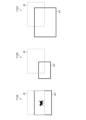
- FIG. 3 is an explanatory diagram showing an example of a display image DSI1 generated by changing the gradation characteristics of a visible light image VSI1 based on the temperature distribution of an infrared image IRI1.
- the visible light image VSI1 shown in the upper left of Fig. 3 is an example of a visible light image captured using a visible light camera.
- the infrared image IRI1 shown in the lower left of Fig. 3 is an example of an infrared image obtained by capturing the same subject as the visible light image VSI1 using an infrared camera.
- the area of the main subject MS1 is detected based on a set temperature range from the temperature distribution of the subject contained in the infrared image IRI1, and the corresponding area of the main subject MSv1 is detected in the visible light image VSI1 based on the position information of the area of the main subject MS1.
- an example is shown in which the area of a cat, which is the main subject MS1, is detected from the infrared image IRI1. This makes it possible to divide the visible light image VSI1 into the area of the main subject MSv1 and areas other than the main subject MSv1.
- the area of the main subject MSv1 is an example of a "first area" in this disclosure, and the area other than the main subject MSv1 is an example of a "second area" in this disclosure.
- FIG. 3 shows an example of a display image DSI1 in which the gamma value applied to the density conversion of pixel values in areas other than the main subject MSv1 in the visible light image VSI1 has been changed, and the display density of areas other than the main subject MSv1 has become brighter than before the density conversion.
- Fig. 4 is an example of a setting screen that accepts the designation of the set temperature range.
- the setting screen as shown in Fig. 4 is displayed on the display unit 16 under the control of the processor 4.
- the display control device 2 is preferably configured to allow the user to arbitrarily change the set temperature range that is the temperature threshold that defines the temperature condition of the detection target. For example, as shown in Fig. 4, it is preferable that a reference set temperature is displayed for each type of subject to be detected.
- the temperature range “Humans and animals (M: 35-38 degrees)” is selected. If birds are to be detected, the temperature range "Birds (H: 39 degrees or higher)” is selected.
- “User specified” is selected, a numeric input box is displayed, allowing the user to specify any temperature range.
- the temperature range specified by the user is stored in the storage device 6 and may be added to the menu as a user-specified set temperature range.
- multiple set temperature ranges can be selected. For example, multiple types of subjects can be selected as detection targets, and can also be set in combination with user specifications.
- the set temperature range is the union of all the specified temperature ranges. For example, in the setting screen shown in Figure 4, if both "Humans/Animals (M: 35-38 degrees)" and “User Specified” are selected, and "30-37 degrees” is specified by the user, the set temperature range is set to the union of these, a temperature range of 30°C to 38°C.
- the set temperature range is set as the union of these, to a temperature range of 20°C to 25°C and 39°C or higher.
- the upper temperature threshold for detecting birds does not need to be set, or a specific value such as 43°C may be set.
- the settings screen may also display a "detection OFF" option that does not detect the main subject using the infrared image IRI.
- detection OFF the process of controlling the display density of the visible light image based on the temperature distribution of the infrared image IRI is not performed. This makes it possible to display the visible light image VSI before the density change.
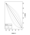
- [About image density conversion (gamma correction) processing] 5 is a graph showing an example of input/output characteristics of gamma correction.
- the horizontal axis represents the input gradation value, and the vertical axis represents the output gradation value.
- Gamma correction for an image with 256 gradations expressed as values from 0 to 255 converts pre-correction gradation value X into post-correction gradation value Y using the following formula (1).
- Y 255 ⁇ (X/255) 1/ ⁇ (1)
- the image When ⁇ >1, the image will be bright overall, and when ⁇ 1, the image will be dark overall.
- the pixel values are converted and an image for display is generated.
- the pixel values can be understood as the density values of the pixels.
- gamma correction is performed by applying different gamma values to the area of the main subject and areas other than the main subject in the visible light image VSI, thereby generating an image for display by providing a density difference in display between the area of the main subject and areas other than the main subject.
- the pixel values of the main subject area in the visible light image VSI are left as is (no density conversion), and the gamma value is changed for pixel values of areas other than the main subject, and gamma correction (conversion) is performed.
- a may be set to, for example, 0.4, and b to, for example, 2.5.
- the display density of areas other than the main subject be freely set by the user so that the user can set a density that is easy to see, rather than being limited to the above default settings.
- the user may freely set the density value in the range of 0 to 255, or may specify a gamma value to be applied to the conversion of pixel values of areas other than the main subject.
- the processor 4 accepts, via the operation unit 18, a specification of a gradation setting to be applied to the display of areas other than the main subject, and changes the gradation characteristics of areas other than the main subject according to the specified gradation setting.
- FIG. 6 is an example of a display image DSI2 generated when the brightness of the main subject MSv2 included in the visible light image VSI2 is brighter than a threshold value.
- the area of the white cat which is the main subject MSv2 in the visible light image VSI2 has a large pixel value and is bright, so it is preferable to change the gradation characteristics and perform density conversion so that the area other than the main subject MSv2 is displayed darker.
- the average density of the main subject MSv2 can be calculated as the average value of the pixel values in the area of the main subject MSv2.
- the threshold value to be compared with the average density may be, for example, 127.5, which is the central value of 256 gradations.
- the average density is an example of an index value related to the brightness of the main subject MSv2.
- other representative values such as the median or mode, or a new index value defined by combining multiple statistics, may be used.
- FIG. 7 is an example of a display image DSI3 that is generated when the brightness of the main subject MSv3 contained in the visible light image VSI3 is darker than a threshold value.
- the area of the black cat that is the main subject MSv3 in the visible light image VSI3 has small pixel values and is dark, so it is preferable to change the gradation characteristics and perform density conversion so that the areas other than the main subject MSv3 are displayed brighter.
- FIG. 8 is an explanatory diagram showing an example of an image density setting screen 30 for setting the display density of areas other than the main subject MSv4.
- the left diagram F8A in Fig. 8 shows an example of the screen when the display density of areas other than the main subject MSv4 is set to level 1, the darkest level of the seven levels, using a brightness adjustment bar 32 that can change the display density of areas other than the main subject MSv4 to seven levels from level 1 to level 7.
- the center diagram F8B in Fig. 8 shows an example of the screen when it is set to level 4
- the right diagram F8C shows an example of the screen when it is set to level 7.
- the image density setting screen 30 displays a brightness adjustment bar 32 at the bottom of the image display area 34.
- An inverted triangle mark 36 displayed at the top of the brightness adjustment bar 32 indicates the currently selected level.
- Each level from level 1 to level 7 may be determined to correspond to, for example, the seven types of gamma values shown in FIG. 4.
- the image display area 34 displays an image when the brightness is set to the currently selected level.
- the user can check the image displayed in the image display area 34 and select the desired brightness level via the operation unit 18. After selecting the desired brightness level, the user can press the set button 38 to set the display density of the area other than the main subject MSv4.
- this method of stepwise density setting is not limited to this, and a user interface that allows the user to freely specify a density conversion curve (gamma curve) may be adopted.
- the display density of the area of the main subject MSv4 may also be configured to be set in a similar manner.
- the setting of the display density of the area of the main subject MSv4 may be the same as the setting of the display density when the visible light image VSI is displayed directly on the display unit 16 without using the information of the infrared image IRI.
- [Explanation of the functional configuration of the display control device] 9 is a block diagram showing the functional configuration of the display control device 2.
- the processor 4 functions as an infrared image receiving unit 40, a temperature information conversion unit 42, a temperature range setting unit 44, a main subject region detection unit 46, a visible light image receiving unit 50, a corresponding region detection unit 51, a density evaluation unit 52, a gradation characteristic control unit 54, a density conversion unit 56, and a display image output unit 58.
- the infrared image receiving unit 40 receives input of an infrared image IRI captured using an infrared sensor.
- the temperature information conversion unit 42 converts the infrared image IRI acquired via the infrared image receiving unit 40 into temperature information.
- the temperature information conversion unit 42 may be configured to generate, for example, a heat map image showing the temperature distribution of the subject contained in the infrared image IRI.
- the heat map image generated based on the infrared image IRI is an image in which the infrared image IRI is converted into temperature information, and can be understood as an "infrared image" in substance.
- the temperature range setting unit 44 sets the temperature range of the object to be detected as the main object among the objects contained in the infrared image IRI. For example, the temperature range setting unit 44 sets the union of the temperature conditions specified on the setting screen for the set temperature range described in FIG. 4 as the set temperature range.
- the main subject area detection unit 46 detects the area of the subject that falls within the set temperature range from the infrared image IRI as the area of the main subject based on the temperature distribution of the subject contained in the infrared image IRI and the set temperature range set by the temperature range setting unit 44. Information on the area of the main subject detected by the main subject area detection unit 46 is provided to the corresponding area detection unit 51 and the gradation characteristic control unit 54.
- the visible light image receiving unit 50 receives input of a visible light image VSI captured using a visible light sensor.
- the corresponding area detection unit 51 identifies an area on the visible light image VSI that corresponds to the area of the main subject detected by the main subject area detection unit 46. That is, the corresponding area detection unit 51 identifies the corresponding area of the main subject in the visible light image VSI based on information on the area of the main subject detected by the main subject area detection unit 46 and information on the correspondence relationship between the two images.
- the combination of the main subject area detection unit 46 and the corresponding area detection unit 51 detects the area of the main subject from the visible light image VSI based on the temperature information of the infrared image IRI.
- the density evaluation unit 52 evaluates the density of the area of the main subject in the visible light image VSI detected by the corresponding area detection unit 51.
- the density evaluation unit 52 obtains an index value related to brightness, such as the average pixel value (average density) of the area of the main subject, and compares it with a threshold value.
- the gradation characteristic control unit 54 controls the gradation characteristics applied to the display of the visible light image VSI.
- the gradation characteristic control unit 54 includes a main subject area gradation characteristic change unit 60 and a background area gradation characteristic change unit 62.
- the main subject area gradation characteristic change unit 60 performs processing to change the main subject area gradation characteristic TC1 applied to the display of the area of the main subject in the visible light image VSI.
- the main subject area gradation characteristic TC1 may be a gradation characteristic applied to the display of the entire image when the visible light image VSI is displayed on the display unit 16 when processing to control the display density of the visible light image VSI based on detection of the area of the main subject using the infrared image IRI is not performed.
- the background region gradation characteristic modification unit 62 performs processing to modify the background region gradation characteristic TC2 applied to the display of an area other than the main subject in the visible light image VSI.
- background region means an area other than the main subject.
- the background region gradation characteristic modification unit 62 modifies the background region gradation characteristic TC2 based on the evaluation result of the density evaluation unit 52.
- the background region gradation characteristic modification unit 62 can also modify the background region gradation characteristic TC2 in accordance with a density setting specified by the user.
- the density conversion section 56 includes a main subject region density conversion section 64 and a background region density conversion section 66.
- the main subject region density conversion section 64 applies the main subject region gradation characteristic TC1 to perform density conversion of the main subject region in the visible light image VSI.
- the background region density conversion section 66 applies the background region gradation characteristic TC2 to perform density conversion of the regions other than the main subject in the visible light image VSI. After processing by the density conversion section 56, the display image DSI is generated.
- the display image output unit 58 performs output processing of the display image DSI.
- the display image output unit 58 converts the display image DSI into a signal format suitable for display on the display unit 16 and outputs it to the display unit 16. In this way, the display image DSI is displayed on the display unit 16.
- the display control device 2 may also be understood as an image processing device that processes the visible light image VSI and the infrared image IRI.
- the hardware structure of the processing units which execute various processes such as the infrared image receiving unit 40, temperature information conversion unit 42, temperature range setting unit 44, main subject region detection unit 46, visible light image receiving unit 50, corresponding region detection unit 51, density evaluation unit 52, gradation characteristics control unit 54, density conversion unit 56, display image output unit 58, main subject region gradation characteristics change unit 60, background region gradation characteristics change unit 62, main subject region density conversion unit 64, and background region density conversion unit 66 described in FIG. 9 is various processors as shown below.
- processors include CPUs, which are general-purpose processors that execute programs and function as various processing units, GPUs, which are processors specialized for image processing, programmable logic devices (PLDs) such as FPGAs (Field Programmable Gate Arrays), which are processors whose circuit configuration can be changed after manufacture, and dedicated electrical circuits such as ASICs (Application Specific Integrated Circuits), which are processors with a circuit configuration designed specifically to execute specific processes.
- PLDs programmable logic devices
- FPGAs Field Programmable Gate Arrays
- ASICs Application Specific Integrated Circuits
- a single processing unit may be configured with one of these various processors, or may be configured with two or more processors of the same or different types.
- a single processing unit may be configured with multiple FPGAs, or a combination of a CPU and an FPGA, or a combination of a CPU and a GPU.
- Multiple processing units may also be configured with one processor.
- configuring multiple processing units with one processor first, there is a form in which one processor is configured with a combination of one or more CPUs and software, as represented by computers such as clients and servers, and this processor functions as multiple processing units.
- a processor that realizes the functions of the entire system including multiple processing units with a single IC (Integrated Circuit) chip, as represented by System On Chip (SoC).
- SoC System On Chip
- the various processing units are configured using one or more of the above various processors as a hardware structure.
- the hardware structure of these various processors is an electrical circuit that combines circuit elements such as semiconductor elements.
- an infrared camera is used in conjunction with a visible light camera to make it easier to find animals hiding in nature and assist in photographing animals.
- photographers are thought to be taking pictures while looking at visible light images, so it is desirable to use information obtained from infrared images in displaying the visible light images to provide users with useful information displays.
- FIG. 10 and 11 show a specific example of the imaging system 10 according to an embodiment of the present disclosure.
- FIG. 10 is a perspective view of the imaging system 10 seen diagonally from the front
- FIG. 11 is a rear view of the imaging system 10 shown in FIG. 10.
- the imaging system 10 includes a visible light camera 100 and an infrared camera 200.
- the visible light camera 100 is a mirrorless digital single-lens camera that is composed of an interchangeable lens 102 and a camera body 104 to which the interchangeable lens 102 can be attached and detached.
- a body mount (not shown) on which the interchangeable lens 102 is attached is provided on the front of the camera body 104.
- a shutter release button 105, a shutter speed dial 106, an exposure compensation dial 107, a power lever 108, a hot shoe 109, etc. are provided on the top surface of the camera body 104.
- the rear of the camera body 104 is provided with an EVF (Electronic View Finder) 112, a MENU/OK key 114, a cross key 116, a playback button 117, and an LCD (Liquid Crystal Display) 118.
- EVF Electronic View Finder
- MENU/OK key 114 a MENU/OK key 114
- MENU/OK key 114 a MENU/OK key 114
- cross key 116 a playback button
- LCD Liquid Crystal Display
- the LCD 118 functions as a display that displays live view images in shooting mode, plays back and displays captured images in playback mode, and displays various menu screens. Note that in shooting mode, if you bring your eye close to the EVF 112, an eye sensor (not shown) automatically switches the display to the EVF 112, and if you move your eye away, the display switches to the LCD 118.
- the MENU/OK key 114 is an operation key that functions both as a menu button for issuing a command to display a menu on the screen of the LCD 118, and as an OK button for issuing a command to confirm and execute a selection.
- the cross key 116 is an operation unit for inputting instructions in four directions, up, down, left, and right, and functions as a button for selecting an item from a menu screen and for instructing the selection of various setting items from each menu.
- the up and down keys of the cross key 116 function as a zoom switch when shooting or a playback zoom switch in playback mode
- the left and right keys function as frame-by-frame (forward and reverse) buttons in playback mode.
- the playback button 117 is a button for switching to a playback mode in which a captured still image or video is displayed on the LCD 118.
- the hot shoe 109 is an attachment part for attaching an external accessory to the visible light camera 100.
- an infrared camera 200 is attached to the hot shoe 109.
- the visible light camera 100 and the infrared camera 200 are connected by a communication cable 122 capable of sending and receiving data.
- the infrared camera 200 is an external infrared sensor module made up of an infrared lens 202 and a camera body 204 to which the infrared lens 202 is attached.
- the infrared lens 202 is a lens that selectively transmits and focuses light in the infrared range.
- the infrared camera 200 is connected to the visible light camera 100 when used. When the infrared camera 200 is attached to the visible light camera 100, it is preferable that the optical axis of the infrared lens 202 is parallel to the optical axis of the interchangeable lens 102 of the visible light camera 100.
- the angle of view of the infrared camera 200 is preferably wider than the angle of view of the visible light camera 100. Note that it is sufficient that the imaging ranges of the visible light camera 100 and the infrared camera 200 overlap at least partially.
- the infrared camera 200 may be equipped with a light source such as an infrared LED (Light Emitting Diode) that projects infrared rays toward the imaging range.
- a light source such as an infrared LED (Light Emitting Diode) that projects infrared rays toward the imaging range.
- Fig. 12 is an explanatory diagram showing an example of the relationship between the angle of view AV of the visible light camera 100 and the angle of view AI of the infrared camera 200.
- FIG. 12 shows a case where the optical axis of the interchangeable lens 102 of the visible light camera 100 and the optical axis of the infrared lens 202 of the infrared camera 200 are parallel, the focal length of the interchangeable lens 102 and the focal length of the infrared lens 202 are the same, and the size of the image sensor 110 of the visible light camera 100 and the size of the image sensor 210 of the infrared camera 200 are the same.
- the angles of view AV and AI have the same width, and the positions of the angles of view AV and AI are shifted up and down depending on the amount of vertical shift between the optical axis of the interchangeable lens 102 and the optical axis of the infrared lens 202.
- the central diagram F12B of FIG. 12 shows a case where the angle of view of the infrared camera 200 is wider than that of the visible light camera 100, and the respective optical axes are shifted up and down and left and right.
- the right diagram F12C of FIG. 12 shows a case where the angle of view of the infrared camera 200 is narrower than that of the visible light camera 100, and the respective optical axes are shifted up and down and left and right.
- the angle of view AI of the infrared camera 200 may be fixed, for example, the angle of view of a lens with a focal length of 28 mm in 35 mm format.
- the angle of view AI of the visible light camera 100 can be changed by changing the focal length of the interchangeable lens 102.
- the interchangeable lens 102 may be a zoom lens.
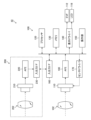
- Fig. 13 is a block diagram showing an example of the internal configuration of the imaging system 10.
- the visible light camera 100 includes an image sensor 110, a processor 120, a memory 130, a display driver 140, an operation unit 150, an input/output interface 160, a sensor driver 170, and an AFE (Analog Front End) 180.
- the processor 120, the memory 130, and the operation unit 150 correspond to the processor 4, the storage device 6, and the operation unit 18 in Fig. 1, respectively.
- the visible light camera 100 is a camera equipped with a display control device 2.
- the image sensor 110 serving as a visible light sensor is composed of a CMOS (Complementary Metal-Oxide Semiconductor) type color image sensor. Note that the image sensor 110 is not limited to a CMOS type, and may also be a CCD (Charge Coupled Device) type image sensor.
- CMOS Complementary Metal-Oxide Semiconductor
- CCD Charge Coupled Device
- the image sensor 110 has red (R), green (G) and blue (B) color filters arranged in a periodic color array on a number of pixels composed of photoelectric conversion elements (photodiodes) arranged two-dimensionally in the x direction (horizontal direction) and y direction (vertical direction), and a microlens is arranged on each photodiode.
- the periodic color array may be, for example, a Bayer array or X-Trans (registered trademark), etc.
- the optical image of the subject formed on the light receiving surface of the image sensor 110 by the imaging optical system of the interchangeable lens 102 is converted into an electrical signal by the image sensor 110.
- An electric charge corresponding to the amount of incident light is accumulated in each pixel of the image sensor 110, and an electrical signal corresponding to the amount of electric charge (signal charge) accumulated in each pixel is read out from the image sensor 110 as an image signal.
- the processor 120 performs overall control of each part of the visible light camera 100 and various processes in accordance with user operations using the operation unit 150.
- the processes performed by the processor 120 include a process of changing the gradation characteristics in the display of a visible light image using an infrared image.
- Memory 130 stores instructions for processor 120 to execute.
- Memory 130 includes a flash memory (not shown), a RAM (Random Access Memory) (not shown), and a ROM (Read Only Memory) (not shown).
- Memory 130 includes a memory card that is removable from camera body 104.
- the flash memory and ROM are non-volatile memories that store firmware, various programs including the display control program according to the embodiment of the present disclosure, and captured images (still images, videos), etc.
- the RAM functions as a working area for processing by the processor 120, and also temporarily stores firmware and display control programs stored in the non-volatile memory. Note that the processor 120 may also incorporate a portion of the memory 130 (RAM).
- the display driver 140 converts the input digital image signal into a signal format for display and outputs it sequentially to the EVF 112 or the LCD 118. Note that some or all of the processing functions of the display driver 140 may be included in the processor 120.
- the EVF 112 and the LCD 118 correspond to the display unit 16 in FIG. 1.
- the operation unit 150 includes the shutter release button 105, the shutter speed dial 106, the exposure compensation dial 107, the power lever 108, the MENU/OK key 114, the cross key 116, the playback button 117, etc., shown in Figures 10 and 11.
- the input/output interface 160 includes the hot shoe 109 shown in FIG. 10 and FIG. 11, and a connector portion (not shown) to which the communication cable 122 is connected.
- the input/output interface 160 transmits and receives data and signals to and from the infrared camera 200.
- the sensor driver 170 controls the reading of image signals from the image sensor 110 according to instructions from the processor 120.
- the sensor driver 170 also has an electronic shutter function that, in response to an electronic shutter control signal from the processor 120, discharges (resets) the electric charge accumulated in each pixel of the image sensor 110 and starts exposure.
- the AFE 180 performs various analog signal processing on the analog image signal obtained by capturing an image of a subject with the image sensor 110, and converts the image signal after analog processing into a digital image signal.
- the analog processing in the AFE 180 includes, for example, color separation processing and AGC (Automatic Gain Control).
- the AGC functions as a sensitivity adjustment section that adjusts the sensitivity during shooting, and adjusts the gain of the amplifier that amplifies the input image signal so that the signal level of the image signal falls within an appropriate range.
- the sensitivity during shooting may be, for example, ISO sensitivity (ISO: International Organization for Standardization).
- the RGB pixel-by-pixel image data (mosaic image data) output via the image sensor 110 and the AFE 180 is input to the memory 130 and temporarily stored therein.
- the image sensor 110 is a CMOS image sensor
- the AFE 180 is often built into the image sensor 110.
- the processor 120 also functions as a digital signal processing unit that performs various types of digital signal processing on image data temporarily stored in the memory 130. That is, the processor 120 performs digital signal processing such as offset processing, gain control processing including sensitivity correction, gamma correction processing, demosaic processing, RGB/YCrCb conversion processing, etc. on the image data input via the AFE 180, and stores the image data after digital signal processing back in the memory 130.
- demosaic processing is, for example, in the case of the image sensor 110 consisting of RGB three-color filters, a process of calculating all RGB color information for each pixel from a mosaic image consisting of RGB, and generating image data of three RGB planes that have been synchronized from the mosaic data (point-sequential RGB data).
- Demosaic processing is also called demosaicing processing or synchronization processing.
- the RGB/YCrCb conversion process converts the synchronized RGB data into luminance data (Y) and color difference data (Cr, Cb).
- the processor 120 when recording a still image or a moving image, the processor 120 performs a compression process on the uncompressed luminance data Y and color difference data Cb, Cr temporarily stored in the RAM of the memory 130.
- the data In the case of a still image, the data is compressed in, for example, JPEG (Joint Photographic coding Experts Group) format, and in the case of a moving image, the data is compressed in, for example, H.264 format.
- the compressed image data is recorded in the flash memory of the memory 130.
- the processor 120 reads out the compressed image data from the flash memory of the memory 130 in the playback mode, performs an expansion process on the read image data, generates uncompressed image data, and displays it on the LCD 118 or the like via the display driver 140.
- the processor 120 When the processor 120 causes the EVF 112 or the LCD 118 to display a live view image, the image is captured at a predetermined frame rate and digitally processed, and the digital image signal is output to the display driver 140.
- the frame rate may be, for example, 30 fps (frames per second) or 60 fps.
- the display driver 140 converts the input time-series digital image signals into a signal format for display and outputs them sequentially to the EVF 112 or LCD 118. This allows the captured image to be displayed in real time on the EVF 112 or LCD 118.
- the shutter release button 105 is a shooting instruction unit for inputting shooting instructions for still images and videos, and is configured as a two-stroke switch with a so-called “half press” (S1 press) and “full press” (S2 press).
- an S1_ON signal is output, and when it is pressed further from the “half-press” to the “full press,” an S2_ON signal is output.
- the processor 120 executes shooting preparation processing such as autofocus (AF) control and auto exposure (AE) control, and when the S2_ON signal is output, it executes still image shooting processing and recording processing.
- the processor 120 calculates the values required for AF control based on the digital image signal.
- contrast AF for example, the processor 120 calculates the integrated value (focus evaluation value) of the high frequency components of the G signal within a specified AF area.
- the processor 120 moves the focus lens included in the lens group of the interchangeable lens 102 to the position where the focus evaluation value is maximized during AF control, that is, the position where the contrast is maximized.
- AF is not limited to contrast AF, and may be, for example, phase difference AF that detects the amount of defocus based on pixel data from phase difference detection pixels provided in the image sensor and moves the focus lens so that this defocus amount becomes zero.
- the processor 120 When performing AE control, the processor 120 detects the brightness of the subject (subject luminance) and calculates an exposure value, which is a numerical value required for AE control that corresponds to the subject luminance.
- the exposure value is also called an EV value (exposure value).
- the processor 120 can determine the F-number (aperture value), shutter speed, and ISO sensitivity from a specified program diagram based on the calculated EV value, and perform AE control.
- AF control and AE control are performed automatically when the auto mode is set by the operation unit 150, and AF control and AE control are not performed when the manual mode is set.
- the camera body 104 in video recording mode, when the shutter release button 105 is pressed all the way down and an S2_ON signal is output, the camera body 104 goes into video recording mode to start recording video, and executes image processing and recording processing of the video. After that, when the shutter release button 105 is pressed all the way down again and an S2_ON signal is output, the camera body 104 goes into standby mode and temporarily suspends the video recording process.
- the infrared camera 200 also includes an image sensor 210, an AFE 220, and an input/output interface 230.
- the image sensor 210 receives light in a wavelength range that includes the infrared range and outputs a captured image.
- the image sensor 210 is composed of a CMOS type or CCD type image sensor.
- the image sensor 210 has microlenses arranged on each of a number of pixels that are composed of photodiodes arranged two-dimensionally in the x and y directions.
- the optical image of the subject formed on the light receiving surface of the image sensor 210 by the imaging optical system of the infrared lens 202 is converted into an electrical signal by the image sensor 210.
- An electric charge corresponding to the amount of incident light is accumulated in each pixel of the image sensor 210, and an electrical signal corresponding to the amount of electric charge (signal charge) accumulated in each pixel is read out from the image sensor 210 as an image signal.
- the AFE 220 performs various analog signal processing on the analog image signal obtained by capturing an image of a subject using the image sensor 210, and converts the image signal after the analog processing into a digital image signal.
- the value of each pixel in the infrared image captured by the infrared camera 200 indicates the intensity of infrared light, which is proportional to the temperature of the subject.
- the frame rate of the infrared camera 200 may be the same as the frame rate of the visible light camera 100.
- the frame rate of the infrared camera 200 may be lower than the frame rate of the visible light camera 100.
- the visible light camera 100 and the infrared camera 200 enter a shooting standby state.
- the visible light camera 100 and the infrared camera 200 start shooting video.
- the shot video is displayed as a live view image on the EVF 112 or LCD 118.
- the user can visually check the live view image displayed on the EVF 112 or LCD 118 to determine the composition, confirm the subject they want to photograph, and set the shooting conditions.
- the visible light image density change process that is applied to the display of the live view image when using the infrared camera 200.
- FIG. 14 is a flowchart showing an example of a process for changing the density of a visible light image in a live view display.
- step ST11 the processor 120 determines whether the infrared camera 200 is attached. For example, the processor 120 checks whether there is an electrical connection between the visible light camera 100 and the infrared camera 200, and determines whether to use the infrared camera 200.
- step ST11 the processor 4 proceeds to step ST12.
- step ST12 the processor 120 acquires the visible light image VSI captured by the image sensor 110 and the infrared image IRI captured by the image sensor 210.
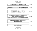
- step ST13 the processor 120 acquires temperature information from the infrared image IRI.
- step ST14 the processor 120 acquires information on the set temperature range to be applied to detection of the area of the main subject contained in the infrared image IRI.
- This set temperature range may be set by the user before shooting, for example, by the method described with reference to FIG. 4.
- the processor 120 distinguishes between pixels within the set temperature range and pixels outside the set temperature range from the temperature information of each pixel in the infrared image IRI, and detects the area of pixels within the set temperature range as the area of the main subject.
- step ST15 the processor 120 determines whether the user has set a different density setting (user setting) from the default setting when displaying the live view image.
- step ST15 If the result of the determination in step ST15 is No, i.e., if the user does not specify a set concentration, the default setting is applied and the process proceeds to step ST16.
- the processor 120 determines whether each pixel in the visible light image VSI corresponds to a pixel in the infrared image IRI that is within the set temperature range.
- the processor 120 may extract pixels from the visible light image VSI that correspond to pixels in the set temperature range based on the correspondence between the pixel positions of the infrared image IRI and the visible light image VSI.
- the processor 120 determines that the region of pixels on the visible light image VSI that correspond to pixels in the infrared image IRI that are within the set temperature range is the region of the main subject in the visible light image VSI.
- the processor 120 may determine that the region of pixels on the visible light image VSI that correspond to pixels outside the set temperature range in the infrared image IRI is the region of the main subject in the visible light image VSI.
- step ST16 If the result of the determination in step ST16 is a Yes determination, i.e., if the pixel corresponds to a pixel within the set temperature range in the infrared image IRI and belongs to the area of the main subject in the visible light image VSI, the processor 120 proceeds to step ST19.
- step ST19 the processor 120 does not perform density conversion on the pixel (does not change the pixel value) and leaves the density unchanged. After step ST19, the processor 120 proceeds to step ST23.
- step ST16 determines whether the pixel corresponds to a pixel in the infrared image IRI that is outside the set temperature range and belongs to an area other than the main subject in the visible light image VSI. If the pixel corresponds to a pixel in the infrared image IRI that is outside the set temperature range and belongs to an area other than the main subject in the visible light image VSI, the processor 120 proceeds to step ST17 and evaluates the density of the area of the main subject.
- the processor 120 evaluates the density (brightness) of the area of the main subject in the visible light image VSI, and determines whether it is brighter than a threshold value. For example, the processor 120 determines whether the average density of the main subject is greater than a threshold value of 127.5.
- the average density here is an example of an index for evaluating the density of the area of the main subject.
- step ST17 If the result of the determination in step ST17 is Yes, i.e., if the density of the main subject area is brighter than the threshold, the processor 120 proceeds to step ST20.
- a is a value smaller than 1, and may be, for example, 0.4.
- step ST17 determines whether the density of the main subject area is darker than the threshold value. If the result of the determination in step ST17 is No, i.e., if the density of the main subject area is darker than the threshold value, proceed to step ST21.
- b is a value greater than 1, and may be, for example, 2.5.
- step ST15 determines whether the user has specified a set concentration. If the determination result in step ST15 is Yes, i.e., if the user has specified a set concentration, the processor 120 proceeds to step ST18.
- step ST18 the processor 120 determines whether each pixel in the visible light image VSI corresponds to a pixel in the infrared image IRI that is outside the set temperature range.
- step ST18 If the result of the determination in step ST18 is No, i.e., if the pixel belongs to the area of the main subject in the visible light image VSI, the processor 120 proceeds to step ST19.
- step ST18 if the result of the determination in step ST18 is Yes, i.e., if the pixel belongs to the area of the main subject in the visible light image VSI, the processor 120 proceeds to step ST22.
- c is, for example, a gamma value corresponding to the brightness level specified by the user on the image density setting screen 30.
- step ST23 density conversion is performed by applying the gamma value determined in any one of steps ST19 to ST22.
- Steps ST13 to ST23 are performed on a pixel-by-pixel basis in the visible light image VSI.
- step ST24 the processor 120 determines whether or not the processing of the final pixel in the visible light image VSI has been completed. If the determination result in step ST24 is No, the processor 120 changes the target pixel to the next pixel, returns to step ST13, and repeats steps ST13 to ST22.
- step ST24 When processing has been completed for all pixels in the visible light image VSI and the determination result in step ST24 is Yes, the processor 120 ends the flowchart in FIG. 14.
- a display image DSI is generated as a live view image, and the display image DSI is displayed on the EVF 112 or the LCD 118.
- the process shown in the flowchart of FIG. 14 may be performed for each frame of the live view image.
- step ST11 the processor 120 may end the flowchart of FIG. 14 and proceed to a processing flow in which a live view image is displayed by applying a publicly known display control method to a visible light image without using an infrared image.
- the imaging system 10 is preferably configured to be able to switch between a first display method, which uses information from the infrared image IRI to change the density of areas other than the main subject of the visible light image VSI and display the image, and a second display method, which displays the visible light image VSI (before the density change) without performing such density change processing, at the user's discretion.
- the imaging system 10 may be configured to allow the user to select the first display method or the second display method from a menu screen on which various settings of the imaging system 10 are made.
- processing functions of the display control device 2 described in the above embodiment may be realized by cloud computing, and it is also possible to provide a service that provides the processing functions as a Software as a Service (SaaS) service.
- SaaS Software as a Service
- IRI infrared image
- VSI visible light image
- the user can set a preset temperature range that will be the temperature condition when detecting the area of the main subject from the infrared image IRI. This makes it possible for the user to easily find and display only the subject they wish to photograph.
- the display of the live view image can be switched to the display of the visible light image VSI before the density change, or can be returned to the display of the live view image after the density change, via a user interface such as a menu screen.
- a user interface such as a menu screen.
- the density is left unchanged for the area of the main subject in the visible light image VSI, but the display density of the area of the main subject may also be changed by modifying the gradation characteristics.
- One of the gradation characteristics applied to the area of the main subject in the visible light image VSI and the gradation characteristics applied to areas other than the main subject may have a gamma value of 1 or more, and the other may have a gamma value of less than 1, thereby changing the display density between the area of the main subject and the area other than the main subject.
- the infrared camera 200 is attached to the visible light camera 100 is not limited to the examples shown in Figures 10 and 11.
- the infrared camera 200 may be fixed to a camera grip (not shown) and attached to the visible light camera 100 via the camera grip.
- the visible light camera 100 and the infrared camera 200 may be fixed to a common camera platform, or each may be fixed to a separate camera platform.
- the technology disclosed herein is not limited to the imaging system 10 illustrated in Figures 10 and 11, but can be applied to various system forms, such as a surveillance camera system, an in-vehicle camera system, a drone imaging system, a wearable camera system, a broadcast video imaging system, or an imaging system that combines a camera-equipped mobile terminal such as a smartphone with an infrared camera.
- Processor 122 Communication cable 130... Memory 140... Display driver 150... Operation unit 160... Input/output interface 170... Sensor driver 180... AFE 200... infrared camera 202... infrared lens 204... camera body 210... image sensor 220...
Landscapes
- Engineering & Computer Science (AREA)
- Multimedia (AREA)
- Signal Processing (AREA)
- Physics & Mathematics (AREA)
- General Physics & Mathematics (AREA)
- Human Computer Interaction (AREA)
- Studio Devices (AREA)
Priority Applications (1)
| Application Number | Priority Date | Filing Date | Title |
|---|---|---|---|
| JP2025510231A JPWO2024203227A1 (https=) | 2023-03-29 | 2024-03-11 |
Applications Claiming Priority (4)
| Application Number | Priority Date | Filing Date | Title |
|---|---|---|---|
| JP2023-053927 | 2023-03-29 | ||
| JP2023053927 | 2023-03-29 | ||
| JP2023-150561 | 2023-09-15 | ||
| JP2023150561 | 2023-09-15 |
Publications (1)
| Publication Number | Publication Date |
|---|---|
| WO2024203227A1 true WO2024203227A1 (ja) | 2024-10-03 |
Family
ID=92905686
Family Applications (1)
| Application Number | Title | Priority Date | Filing Date |
|---|---|---|---|
| PCT/JP2024/009328 Ceased WO2024203227A1 (ja) | 2023-03-29 | 2024-03-11 | 表示制御装置、表示制御方法、撮影システム及びプログラム |
Country Status (2)
| Country | Link |
|---|---|
| JP (1) | JPWO2024203227A1 (https=) |
| WO (1) | WO2024203227A1 (https=) |
Citations (6)
| Publication number | Priority date | Publication date | Assignee | Title |
|---|---|---|---|---|
| JPH0258480A (ja) * | 1988-08-24 | 1990-02-27 | Nippon Telegr & Teleph Corp <Ntt> | 被写体像抽出方式 |
| JP2011091845A (ja) * | 2010-12-10 | 2011-05-06 | Fujitsu Ltd | 撮像システム及び制御装置 |
| JP2015087949A (ja) * | 2013-10-30 | 2015-05-07 | キヤノン株式会社 | 画像処理装置及びその制御方法、プログラム、記憶媒体 |
| JP2016127388A (ja) * | 2014-12-26 | 2016-07-11 | キヤノン株式会社 | 画像処理装置およびその制御方法、プログラムならびに記憶媒体 |
| JP2020524430A (ja) * | 2017-06-04 | 2020-08-13 | アップル インコーポレイテッドApple Inc. | ユーザインタフェースカメラ効果 |
| JP7188397B2 (ja) * | 2017-12-04 | 2022-12-13 | ソニーグループ株式会社 | 画像処理装置及び画像処理方法 |
-
2024
- 2024-03-11 JP JP2025510231A patent/JPWO2024203227A1/ja active Pending
- 2024-03-11 WO PCT/JP2024/009328 patent/WO2024203227A1/ja not_active Ceased
Patent Citations (6)
| Publication number | Priority date | Publication date | Assignee | Title |
|---|---|---|---|---|
| JPH0258480A (ja) * | 1988-08-24 | 1990-02-27 | Nippon Telegr & Teleph Corp <Ntt> | 被写体像抽出方式 |
| JP2011091845A (ja) * | 2010-12-10 | 2011-05-06 | Fujitsu Ltd | 撮像システム及び制御装置 |
| JP2015087949A (ja) * | 2013-10-30 | 2015-05-07 | キヤノン株式会社 | 画像処理装置及びその制御方法、プログラム、記憶媒体 |
| JP2016127388A (ja) * | 2014-12-26 | 2016-07-11 | キヤノン株式会社 | 画像処理装置およびその制御方法、プログラムならびに記憶媒体 |
| JP2020524430A (ja) * | 2017-06-04 | 2020-08-13 | アップル インコーポレイテッドApple Inc. | ユーザインタフェースカメラ効果 |
| JP7188397B2 (ja) * | 2017-12-04 | 2022-12-13 | ソニーグループ株式会社 | 画像処理装置及び画像処理方法 |
Also Published As
| Publication number | Publication date |
|---|---|
| JPWO2024203227A1 (https=) | 2024-10-03 |
Similar Documents
| Publication | Publication Date | Title |
|---|---|---|
| JP6780745B2 (ja) | 電子機器 | |
| JP5930079B2 (ja) | 電子機器 | |
| JP2010093472A (ja) | 撮像装置および撮像装置用信号処理回路 | |
| CN102892008A (zh) | 双图像捕获处理 | |
| CN110086980A (zh) | 电子设备 | |
| US10762600B2 (en) | Image processing apparatus, image processing method, and non-transitory computer-readable recording medium | |
| US7609291B2 (en) | Device and method for producing an enhanced color image using a flash of infrared light | |
| CN106878624A (zh) | 摄像装置和摄像方法 | |
| JP2010147786A (ja) | 撮像装置及び画像処理方法 | |
| JP2000278595A (ja) | デジタルカメラ及び撮像方法 | |
| JP4914651B2 (ja) | 電子撮像装置及び電子撮像方法 | |
| WO2024203227A1 (ja) | 表示制御装置、表示制御方法、撮影システム及びプログラム | |
| JP2010171930A (ja) | 撮影装置及び撮影方法 | |
| US12301991B2 (en) | Outputting information in a case in which a focus evaluation value of the latest frame exceeds an allowable value set based on the maximum evaluation value during a manual focus period | |
| JP5094686B2 (ja) | 画像処理装置、画像処理方法、および、画像処理プログラム | |
| JP2016158294A (ja) | 電子機器、電子機器の制御方法、及び制御プログラム | |
| WO2024203226A1 (ja) | 表示制御装置、表示制御方法及びプログラム、撮影システム | |
| KR20080029051A (ko) | 이미지 센서를 구비한 장치 및 영상 획득 방법 | |
| JP7283488B2 (ja) | 撮像素子及び電子機器 | |
| WO2025041498A1 (ja) | 表示制御装置、表示制御方法、プログラム及び撮像装置 | |
| JP2008017198A (ja) | 光源色算出装置、光源色算出方法及び撮影装置 | |
| JP7726766B2 (ja) | 撮像装置、撮像方法、及びプログラム | |
| JP6822507B2 (ja) | 電子機器 | |
| JP4875399B2 (ja) | 撮像装置及びその制御方法並びに撮像システム | |
| WO2024203225A1 (ja) | 画像処理装置、画像処理方法及びプログラム、撮影システム |
Legal Events
| Date | Code | Title | Description |
|---|---|---|---|
| 121 | Ep: the epo has been informed by wipo that ep was designated in this application |
Ref document number: 24779357 Country of ref document: EP Kind code of ref document: A1 |
|
| ENP | Entry into the national phase |
Ref document number: 2025510231 Country of ref document: JP Kind code of ref document: A |
|
| WWE | Wipo information: entry into national phase |
Ref document number: 2025510231 Country of ref document: JP |
|
| NENP | Non-entry into the national phase |
Ref country code: DE |
|
| 122 | Ep: pct application non-entry in european phase |
Ref document number: 24779357 Country of ref document: EP Kind code of ref document: A1 |