WO2024203208A1 - 信号処理装置、信号処理方法、プログラム - Google Patents
信号処理装置、信号処理方法、プログラム Download PDFInfo
- Publication number
- WO2024203208A1 WO2024203208A1 PCT/JP2024/009273 JP2024009273W WO2024203208A1 WO 2024203208 A1 WO2024203208 A1 WO 2024203208A1 JP 2024009273 W JP2024009273 W JP 2024009273W WO 2024203208 A1 WO2024203208 A1 WO 2024203208A1
- Authority
- WO
- WIPO (PCT)
- Prior art keywords
- signal processing
- pixel data
- thinning
- spectroscopic
- spectroscopic sensor
- Prior art date
- Legal status (The legal status is an assumption and is not a legal conclusion. Google has not performed a legal analysis and makes no representation as to the accuracy of the status listed.)
- Ceased
Links
Images





Classifications
-
- H—ELECTRICITY
- H04—ELECTRIC COMMUNICATION TECHNIQUE
- H04N—PICTORIAL COMMUNICATION, e.g. TELEVISION
- H04N23/00—Cameras or camera modules comprising electronic image sensors; Control thereof
- H04N23/45—Cameras or camera modules comprising electronic image sensors; Control thereof for generating image signals from two or more image sensors being of different type or operating in different modes, e.g. with a CMOS sensor for moving images in combination with a charge-coupled device [CCD] for still images
-
- H—ELECTRICITY
- H04—ELECTRIC COMMUNICATION TECHNIQUE
- H04N—PICTORIAL COMMUNICATION, e.g. TELEVISION
- H04N23/00—Cameras or camera modules comprising electronic image sensors; Control thereof
- H04N23/60—Control of cameras or camera modules
Definitions
- This technology relates to a signal processing device, a signal processing method, and a program, and in particular to a technical field related to the transmission of spectroscopic sensor images obtained by the light receiving operation of a spectroscopic sensor.
- Spectroscopic sensors are known that obtain multiple narrowband images that are wavelength characteristic analysis images of light from a subject, in other words, analysis images of the subject's spectral information (spectral spectrum).
- applications have been developed that perform various analyses of a subject based on the spectral information obtained by the spectroscopic sensor, such as estimating the vegetation state of plants or the condition of human skin, based on these multiple narrowband images.
- Spectral sensor images are made up of a lot of pixel data, just like images captured by an RGB sensor to obtain a color image, so the amount of data transmitted tends to increase, which can strain the bandwidth of the transmission path.
- Patent Document 1 discloses a technology that improves transmission efficiency by providing a mode for outputting all pixels and a mode for outputting only some pixels for image data obtained by an image sensor, thereby avoiding the transmission of data for all pixels for each frame.
- This technology was developed in consideration of the above circumstances, and aims to improve the transmission efficiency of spectroscopic sensor images.
- a first signal processing device includes a signal processing unit that performs an overall output process for outputting pixel data of all regions and all wavelengths for a spectroscopic sensor image, which is a spectroscopic image obtained by a light receiving operation of a spectroscopic sensor, obtained in a first frame period, and a thinning output process for thinning out and outputting some pixel data for the spectroscopic sensor image obtained in a second frame period different from the first frame period.
- a second signal processing device is a signal processing device that performs: an overall output process for outputting pixel data of all regions and all wavelengths for a spectroscopic sensor image obtained in a first frame period, the spectroscopic sensor image being a spectroscopic image obtained by a light receiving operation of a spectroscopic sensor; and a thinning output process for thinning out and outputting a portion of pixel data for the spectroscopic sensor image obtained in a second frame period different from the first frame period, and outputting metadata indicating interpolation data for the thinned-out pixel data as metadata for the thinned-out pixel data.
- the signal processing device includes: a receiving unit that receives the pixel data of all regions and all wavelengths output by the overall output process, and the thinned-out pixel data and the metadata output by the thinned-out output process; and an interpolation unit that performs an interpolation process on the thinned-out pixel data based on the pixel data of all regions and all wavelengths and the metadata received by the receiving unit.
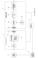
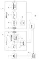
- FIG. 1 is a block diagram showing an example of a schematic configuration of a spectroscopic camera including a signal processing device according to a first embodiment.
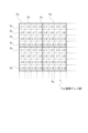
- 2 is a diagram illustrating a schematic configuration example of a pixel array unit of a spectroscopic sensor.
- FIG. 5A and 5B are explanatory diagrams of band narrowing processing in the embodiment.
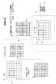
- 4A and 4B are explanatory diagrams of a thinning method and an interpolation method according to the first embodiment;
- FIG. 4 is an explanatory diagram of an example of metadata in the embodiment.
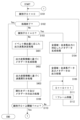
- 1 is a flowchart illustrating an example of a processing procedure for implementing a thinning method according to a first embodiment.
- FIG. 11 is an explanatory diagram of an example of a transmission method for a spectroscopic sensor image.
- 11A and 11B are diagrams illustrating another example of a transmission method for a spectroscopic sensor image.
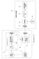
- FIG. 11 is a block diagram showing an example of the schematic configuration of a spectroscopic camera including a signal processing device according to a second embodiment.
- 11A and 11B are diagrams for explaining an example of detection of a region of a moving subject;
- 10 is a flowchart illustrating an example of a processing procedure for implementing a thinning method according to a second embodiment.
- FIG. 11 is an explanatory diagram of an example of a transmission method for a spectroscopic sensor image.
- 11A and 11B are diagrams illustrating another example of a transmission method for a spectroscopic sensor image.
- FIG. 11 is a block diagram showing an example of the schematic configuration of a spectroscopic camera including a signal processing device according to a second embodiment.
- FIG. 13 is a block diagram showing an example of the schematic configuration of a spectroscopic camera including a signal processing device according to a third embodiment.
- 13 is a flowchart illustrating an example of a processing procedure for implementing a thinning method according to a third embodiment.
- 1 is a block diagram showing an example of the schematic configuration of a spectroscopic camera that performs AE detection on a spectroscopic sensor image before thinning processing is performed.
- 11 is a diagram for explaining an example of an AE detection frame.
- FIG. FIG. 13 is a block diagram showing a schematic configuration example of a signal processing device as a modified example.
- 11A and 11B are explanatory diagrams of an example of performing thinning by reducing the image size for only a specific wavelength.
- FIG. 1 is a block diagram showing an example of a schematic configuration of a spectroscopic camera 10 as a first embodiment configured to include a signal processing device as a first embodiment according to the present technology.
- spectroscopic camera refers to a camera equipped with a spectroscopic sensor as a light receiving sensor for obtaining a plurality of narrowband images that serve as wavelength characteristic analysis images of light from a subject.
- light receiving sensor refers to a sensor equipped with a photoelectric conversion element as a sensing element.
- the spectroscopic camera 10 includes a sensor unit 1 , an imaging optical system 2 , an image generating section 3 , an optical system driving section 4 , and a control section 5 .
- the sensor unit 1 includes a spectroscopic sensor 11 , a signal processing unit 12 , and a communication unit 13 .
- the imaging optical system 2 is configured to include various optical elements including lenses such as a focus lens, an aperture mechanism, and the like.
- the pixel array section 11a has a plurality of spectroscopic pixel units Pu formed therein, each of which has a plurality of pixels Px, each of which receives light of a different wavelength band, arranged two-dimensionally in a predetermined pattern.
- the pixel array section 11a has a plurality of spectroscopic pixel units Pu arranged two-dimensionally.
- each spectroscopic pixel unit Pu receives light of a total of 16 wavelength bands, from ⁇ 1 to ⁇ 16, individually at each pixel Px, in other words, an example in which the number of wavelength bands received and separated within each spectroscopic pixel unit Pu (hereinafter referred to as the "number of received wavelength channels") is "16".
- the number of received wavelength channels in the spectroscopic pixel unit Pu may be at least multiple and can be set arbitrarily.
- the number of light-receiving wavelength channels in the spectroscopic pixel unit Pu is defined as "N".
- a spectroscopic image (hereinafter referred to as a "spectroscopic sensor image") obtained by a light receiving operation of the spectroscopic sensor 11 is input to a signal processing unit 12.
- the signal processing unit 12 performs various necessary signal processing, such as a gain adjustment process, on the spectroscopic sensor image output from the spectroscopic sensor 11 and outputs the result.
- the signal processing unit 12 in this embodiment has a function as a thinning-out processing unit F1, which will be described later.
- the communication unit 13 is a communication device for transmitting the spectroscopic sensor image to the outside of the sensor unit 1, and in this example, a communication device compatible with the MIPI (Mobile Industry Processor Interface) communication standard is used.
- MIPI Mobile Industry Processor Interface
- the image generating unit 3 generates M narrowband images based on the spectroscopic sensor images input from the sensor unit 1.
- the image generating unit 3 includes a communication unit 31, a demosaic unit 32, a narrowband image generating unit 33, and in this embodiment, an interpolation unit 34 and a memory unit 35.
- the communication unit 31 is a communication device for performing data communication with the communication unit 13 of the sensor unit 1, and is configured as a communication device that complies with the same communication standard as the communication unit 13, specifically, in this example, the MIPI communication standard.
- the spectroscopic sensor image transmitted to the communication unit 31 is input to the demosaic unit 32 via the interpolation unit 34 .
- the demosaic unit 32 performs demosaic processing on the spectroscopic sensor image.
- the narrowband image generating unit 33 performs narrowband processing (linear matrix processing) based on the wavelength band images for N channels obtained by the demosaic processing, thereby generating M narrowband images from the N wavelength band images.
- FIG. 3 is a diagram illustrating the band narrowing process for obtaining M narrowband images.
- a narrowband image for M channels is obtained by performing a predetermined matrix operation for each pixel position based on the waveband image for N channels obtained by the demosaic process by the demosaic unit 32.
- the process of obtaining pixel values for M channels ( I'0 to I'M-1 in the figure) by a matrix operation using pixel values for N channels ( I0 to IN-1 in the figure) for each pixel position is the band narrowing process.
- the calculation formula for the narrowband processing can be expressed as the following [Equation 1].
- a total of N ⁇ M narrowband coefficients C are used: C 0 [0] to C 0 [N-1] for obtaining pixel value B 0 , C 1 [0] to C 1 [N-1] for obtaining pixel value B 1, ..., C M-1 [0] to C M-1 [N-1] for obtaining pixel value B M-1 .
- control unit 5 is configured with a microcomputer having, for example, a CPU (Central Processing Unit), a ROM (Read Only Memory), and a RAM (Random Access Memory), and the CPU performs overall control of the spectroscopic camera 10 by executing processing based on, for example, a program stored in the ROM or a program loaded into the RAM.
- control unit 5 issues instructions to the sensor unit 1 and the image generating unit 3 to perform various operations, to stop operations, and the like.
- the control unit 5 also performs control for AF (Auto Focus) and AE (Auto Exposure).
- the optical system driving unit 4 is provided with an actuator for driving a focus lens and an actuator for driving an aperture mechanism provided in the imaging optical system 2, and the control unit 5 realizes AF control and AE control by controlling the actuators provided in the optical system driving unit 4.
- the AE control involves not only control of the aperture mechanism but also control of the shutter speed of the spectroscopic sensor 11.
- the sensor unit 1 is provided with a detection section that performs detection for AF or AE, and the control section 5 controls the AF or AE based on the detection results by the detection section.
- FIG. 4 is an explanatory diagram of a thinning method and an interpolation method according to the first embodiment.
- the signal processing unit 12 performs a full output process for the spectroscopic sensor image obtained by the spectroscopic sensor 11, which outputs pixel data for all regions and all wavelengths for the spectroscopic sensor image obtained in a first frame period, and a thinning output process for thinning out and outputting some of the pixel data for the spectroscopic sensor image obtained in a second frame period that is different from the first frame period.
- the function of performing thinning in the above-mentioned thinning output process corresponds to the function of the thinning processing unit F1 described above.
- the signal processing unit 12 in this example performs the above-mentioned overall output process periodically at intervals of at least one frame or more.
- the overall output process is performed every s frames (s is a natural number equal to or greater than 1).
- s is a natural number equal to or greater than 1.
- the overall output process is not limited to being performed periodically, and may be performed at non-periodic intervals.
- the image generating unit 3 When the image generating unit 3 receives the pixel data for all areas and all wavelengths output in the overall output process via the communication unit 31, it stores the received pixel data for all areas and all wavelengths in the memory unit 35 (see "Previously received all area and all wavelength data" in Figure 4).
- the signal processing unit 12 also performs the above-mentioned thinning output process in each frame in which the full output process is not performed. During the frame period in which the thinning output process is performed, some of the pixel data is thinned out and output from the spectroscopic sensor image obtained by the spectroscopic sensor 11 during that frame period.
- the signal processing unit 12 in this example performs both wavelength thinning and spatial thinning as the thinning of the spectroscopic sensor image.
- the image region to be transmitted may be, for example, a region designated from the outside.
- the region in which the target subject is captured in the spectroscopic sensor image can be specified to some extent, such as when the subject to be analyzed based on the narrowband image is mainly located in a specific region within the angle of view of the spectroscopic camera 10, the user may perform an operation to designate the region on the spectroscopic camera 10, and the control unit 5 may designate the designated region to the signal processing unit 12 as the image region to be transmitted.
- the information on the image area to be transmitted that is thus instructed to the signal processing unit 12 will be referred to as "output area instruction information".
- the signal processing unit 12 determines the wavelengths to be thinned out in the thinning output process according to a predetermined rule. Specifically, in this example, the wavelengths to be thinned out are switched every time the thinning output process is performed, and the wavelengths to be output in each thinning output process are sequentially determined according to the predetermined rule. Specifically, the signal processing unit 12 in this example determines wavelengths to be thinned out for each thinned-out output process (that is, for each frame) using a round robin method.
- the signal processing unit 12 performs processing to generate metadata that enables the interpolation of the thinned data in the image generating unit 3, which is the receiver of the spectroscopic sensor image, and output the metadata together with the thinned data.
- FIG. 5 is an explanatory diagram of an example of metadata.
- the metadata is generated as MIPI embedded data.
- the metadata in this example is roughly divided into two types of information: "information about all pixels” and "information about the frame in question.”
- the “information on the frame” also includes information on the "number of frames from the total output” which indicates the number of frames from the frame where the total output processing is performed, information on the "output start point” and “number of output pixels” of the spectroscopic sensor image, information on the "size of the output wavelength unit” which is size information of the wavelength unit (output wavelength unit) in the output image, and information on the “breakdown of output wavelength channels” which is the breakdown of the wavelengths included in the output wavelength unit.
- the information “number of frames from total output” stores “0” if the frame is a frame for which total output processing is performed.
- the information on the "size of output wavelength unit” stores “2 ⁇ 2”
- the information on the "breakdown of output wavelength channels” stores information corresponding to ⁇ 1, ⁇ 2, ⁇ 5, and ⁇ 6.
- the image generating section 3 that receives the metadata is provided with an interpolation section 34 .
- the interpolation unit 34 outputs the pixel data for all areas and all wavelengths of the spectroscopic sensor image received by the communication unit 31 to the downstream demosaic unit 32 and also performs processing to store the data in the memory unit 35.
- the interpolation unit 34 performs an interpolation process on the thinned-out pixel data received by the communication unit 31, based on the metadata received together with the thinned-out pixel data and the (latest) pixel data for all regions and all wavelengths stored in the memory unit 35. Then, the interpolation unit 34 outputs the pixel data after the interpolation process (the thinned-out pixel data and the pixel data as the interpolated data) to the demosaic unit 32.
- the interpolation unit 34 can identify the image area to be used for interpolation (the image area that is missing in the post-thinning data) from the pixel data of all areas and all wavelengths stored in the memory unit 35, based on the information on "image size of all pixels,”"output start point,” and "output image size” in the metadata shown in FIG.
- the interpolation unit 34 can identify pixel data to be used for interpolation (pixel data of wavelengths that are missing in the post-thinning data) from the pixel data of all areas and all wavelengths stored in the memory unit 35, based on at least the information on “Breakdown of wavelength channel” and “Breakdown of output wavelength channel” in the metadata shown in FIG. 5 .
- the metadata in this embodiment functions as data that indicates the interpolation data for the thinned pixel data.
- FIG. 6 is a flowchart showing an example of a processing procedure to be executed by the signal processing unit 12 to implement the thinning method according to the first embodiment.
- step S102 the signal processing unit 12 determines whether the process has ended. That is, the signal processing unit 12 determines whether a predetermined condition is met that indicates that the series of processes shown in FIG. 6 should be ended, such as when an instruction to stop operation is received from the control unit 5. If it is determined in step S102 that the above-mentioned predetermined condition is not satisfied and the process does not end, the signal processing unit 12 proceeds to step S103 and determines whether the identifier Df is 0 or not. If the identifier Df is 0, the signal processing unit 12 proceeds to step S104 and performs metadata generation processing corresponding to the full region/full wavelength output. In this case, the metadata may be generated by generating data indicating that the frame is a frame of the full output processing.
- Metadata is generated in which "0" is stored as the “number of frames from the full output” shown in FIG. 5, "(0,0)" is stored as the “output start point", the "output image size” has the same value as the “image size of all pixels”, the "size of the output wavelength unit” has the same value as the “size of the spectral pixel unit”, and the “breakdown of the output wavelength channel” has the same value as the "breakdown of the wavelength channel”.
- step S105 the signal processing unit 12 performs processing to output all-area and all-wavelength data and metadata. That is, processing to output pixel data for all areas and all wavelengths of the spectroscopic sensor image during the frame period, and the metadata generated in step S104 is performed.
- step S105 the signal processing unit 12 proceeds to step S111, increments the value of identifier Df by 1, and then performs processing to wait one frame in step S112, before returning to the aforementioned step S102. If the process is not completed in step S102, a determination is made in step S103 as to whether or not the identifier Df is 0.
- step S106 the signal processing unit 12 proceeds to step S106 and performs output wavelength determination processing.
- This output wavelength determination processing is processing for determining the wavelengths to be output in the thinned output processing, and specifically, in this example, the wavelengths to be output are determined by the round robin method described above. Note that determining the wavelengths to be output in the thinned output processing is synonymous with determining the wavelengths to be thinned.
- step S107 following step S106 the signal processing unit 12 performs metadata generation processing based on the output area instruction information and the determined output wavelength information. That is, metadata is generated in which values according to the output target image area indicated by the output area instruction information are stored as the values of "output start point" and "output image size", and values according to the output target wavelength determined in step S106 are stored as the information of "output wavelength unit size" and "output wavelength channel breakdown".
- the same values as the metadata generated in the metadata generation processing corresponding to the full area/full wavelength output in step S104 are stored as the values of each item in "information of all pixels".
- the value of the identifier Df is stored as the information of "number of frames from total output”.
- step S108 the signal processing unit 12 performs spatial and wavelength thinning processing based on the output area instruction information and the determined output wavelength information. In other words, processing is performed to extract, from the spectroscopic sensor image in the frame, only pixel data of the wavelength determined in step S104 in the image area indicated by the output area instruction information as pixel data to be output.
- step S109 following step S108 the signal processing unit 12 performs processing to output the thinned data and metadata. That is, processing to output the pixel data extracted in step S108 and the metadata generated in step S107 is performed.
- step S110 following step S109 the signal processing unit 12 determines whether the identifier Df is equal to or greater than the threshold value THd.
- the threshold value THd determines the period for executing the overall output process. For example, if the overall output process is executed every 9 frames (every 10 frames), the threshold value THd is set to 9. In other words, if the overall output process is executed every s frames, the threshold value THd is set to s.
- step S110 If it is determined in step S110 that the identifier Df is not equal to or greater than the threshold value THd, the signal processing unit 12 proceeds to the above-mentioned step S111. As a result, if the thinning-out process for the predetermined number of frames has not yet been completed, the identifier Df is incremented in step S111, and then the thinning-out process is performed on the spectroscopic sensor image of the next frame.
- step S110 if it is determined in step S110 that the identifier Df is equal to or greater than the threshold value THd, the signal processing unit 12 returns to step S101 and sets the identifier Df to 0 again. As a result, after the execution of the entire output process, the thinned output process for the predetermined number of frames has been executed, and the entire output process is executed again.
- step S102 If the signal processing unit 12 determines in step S102 that the processing has ended, it ends the series of processing steps shown in FIG. 6.
- FIG. 7 is a flowchart showing an example of a process to be executed by the interpolation unit 34 to implement the interpolation method according to the first embodiment.
- the interpolation unit 34 performs a process of waiting to receive frame data, that is, a process of waiting to receive frame data of the spectroscopic sensor image output from the sensor unit 1 side, specifically, pixel data and metadata of the spectroscopic sensor image.
- the interpolation unit 34 performs a process of decoding the metadata in step S202.
- the interpolation unit 34 determines in step S203 whether the data is all-area/all-wavelength data, i.e., whether the data is pixel data for all areas/all wavelengths output by the total output process. Whether the received data is all-area/all-wavelength data can be determined by whether the value of "number of frames from total output" in the metadata is "0" or not.
- step S203 If it is determined in step S203 that the data is all-area and all-wavelength data, the interpolation unit 34 proceeds to step S204, where it stores the all-area and all-wavelength data in the memory unit 35, and then proceeds to step S205, where it outputs the all-area and all-wavelength data to the demosaic unit 32.
- step S208 determines whether or not the process has ended, that is, whether or not a predetermined condition has been met that indicates that the series of processes shown in FIG. 7 should be ended, such as, for example, an instruction to stop operation has been received from the control unit 5. If it is determined in step S208 that the above-mentioned predetermined condition is not satisfied and the process does not end, the interpolation unit 34 returns to step S201.
- step S203 the interpolation unit 34 advances the process to step S206.
- step S206 the interpolation unit 34 performs a process of interpolating the received thinned data based on the all-area/all-wavelength data and metadata stored in the memory unit 35. That is, the interpolation unit 34 performs a process of interpolating the received thinned data based on the latest all-area/all-wavelength pixel data stored in the memory unit 35 and the metadata decoded in step S202.
- the interpolation unit 34 performs a process of outputting the post-interpolation data, that is, the pixel data after the interpolation process in step S206, to the demosaic unit 32, and the process proceeds to step S208 described above.
- step S208 If it is determined in step S208 that the processing has ended, the interpolation unit 34 ends the series of processing steps shown in FIG. 7.
- the signal processing unit 12 determines the wavelengths to be output in the thinning output process, but the wavelengths to be output may be specified from outside the signal processing unit 12.
- the wavelengths to be output may be specified from outside the signal processing unit 12.
- information specifying the wavelengths corresponding to the specific color as the wavelengths to be output may be input from outside to the signal processing unit 12.
- the signal processing unit 12 performs a process of outputting only pixel data of the wavelengths specified from outside among pixel data of all wavelengths in the spectroscopic sensor image in the thinning output process.
- the wavelength instruction information from the outside may be, for example, instruction information based on a user operation, instruction information from an application that performs analysis processing based on a narrowband image, or the like.
- FIG. 8A shows an example in which pixel data of a spectroscopic sensor image is transmitted as one piece of RAW data without being separated for each wavelength.
- FIG. 8B shows an example of a case where pixel data of a spectroscopic sensor image is separated for each wavelength and transmitted as RAW data for each wavelength.
- the receiving side image generating unit 3 side
- the receiving side does not need to perform a process of separating the pixel data for each wavelength.
- Fig. 9 shows an example of using VC (Virtual Channel) in MIPI to separate and transmit wavelengths for each VC.
- VC Virtual Channel
- FIG. 10 is a block diagram showing an example of the schematic configuration of a spectroscopic camera 10A according to the second embodiment.
- parts that are similar to parts that have already been described will be given the same reference numerals (including processing step numbers) and descriptions thereof will be omitted.
- the spectroscopic camera 10A differs from the spectroscopic camera 10 of the first embodiment shown in FIG. 1 in that a sensor unit 1A is provided instead of the sensor unit 1.
- the sensor unit 1A differs from the sensor unit 1 in that an event sensor 15 and a motion region detection section 16 are added, and in that a signal processing section 12A is provided instead of the signal processing section 12.
- the signal processing unit 12A differs from the signal processing unit 12 in that it has a thinning-out unit F1A instead of the thinning-out unit F1.
- the event sensor 15 is a light receiving sensor known as an EVS (Event Based Sensor), which is a sensor in which multiple pixels having light receiving elements are arranged two-dimensionally and configured to detect a change in the amount of light received at each pixel that is greater than or equal to a predetermined amount as an event.
- the event sensor 15 is also provided with a corresponding optical system, that is, an optical system for guiding light from a subject to the event sensor 15 .
- the event sensor 15 is disposed so as to have a common sensing range with the spectroscopic sensor 11. This allows a subject captured within the angle of view of the spectroscopic sensor 11 to be captured within the angle of view of the event sensor 15 as well.
- the event sensor 15 is configured to output, for each pixel that detects an event, information indicating the position of that pixel (event detection pixel position information) and information indicating the time the event was detected (event detection time information). In addition, the event sensor 15 resets the amount of charge stored in the pixel that detected the event, thereby resetting the pixel that detected the event to a state in which it can detect an event again.
- event detection information the event detection pixel position information and event detection time information output by the event sensor 15 will be referred to as “event detection information.”
- the motion area detection unit 16 detects the area of a moving subject based on the event detection information from the event sensor 15 .
- FIG. 11 is a diagram for explaining an example of detection of a moving subject region by the motion region detection section 16.
- the motion area detection unit 16 detects, for example, area Am that includes both the subject detection area at the latest detection timing (solid line area in Figure 11B) and the subject detection area at the immediately preceding detection timing (dashed line area in Figure 11B) as the area of the moving subject.
- the moving subject area may include at least the subject detection area at the latest detection timing.
- the thinning processing unit F1A outputs only the pixel data of the area of the moving subject detected by the motion area detection unit 16 from the pixel data of all pixels of the spectroscopic sensor image in the thinning output process.
- the flowchart in FIG. 12 shows an example of a processing procedure to be executed by the signal processing unit 12A in order to realize the thinning method according to the second embodiment described above. 6, the thinning out method in this case differs from the flow chart in FIG. 6 in that steps S301, S302, and S303 are performed instead of steps S106, S107, and S108, respectively.
- step S301 the signal processing unit 12A performs a process of determining the detection region as the output region.
- the signal processing unit 12A performs a process of determining the region of the moving subject detected by the motion region detection unit 16 as the image region to be output.
- step S302 following step S301 the signal processing unit 12A performs metadata generation processing based on the output area information. That is, the metadata generation processing is based on the output area information determined in step S301. In this example, only spatial thinning based on the area of the moving subject is performed, so the wavelength-related item information in the "information on the relevant frame" of the metadata stores the same value as when performing the entire output processing, and the values of "output start point" and "output image size” store values based on the determined output area information.
- step S303 following step S302 the signal processing unit 12A performs spatial thinning processing based on the output region information. That is, processing is performed to extract, from among all pixels of the spectroscopic sensor image in the frame, only pixel data within the output region determined in step S301 as pixel data to be output.
- step S303 After executing the thinning process in step S303, the signal processing unit 12A advances the process to step S109.
- the processing on the receiving side is similar to that shown in FIG. 7, so a duplicate explanation will be avoided.
- the event sensor 15 was used to detect the area of the moving subject, but the sensor for detecting the area of the moving subject is not limited to the event sensor 15, and for example, a normal image sensor such as an RGB sensor can also be used.
- a normal image sensor such as an RGB sensor
- the area of the moving subject can be detected by detecting the difference between frames.
- wavelength thinning can also be performed in the second embodiment.
- the spectroscopic sensor 11 when a light receiving sensor (hereinafter referred to as the “separate sensor”) separate from the spectroscopic sensor 11 is provided as in the second embodiment (including the third embodiment described later), it is also possible to configure the spectroscopic sensor 11 to start generating a spectroscopic sensor image when movement of a subject is detected based on light receiving information from the separate sensor.
- the signal processing unit 12A may control the spectroscopic sensor 11 to start the operation of generating a spectroscopic sensor image.
- the separate sensor used to detect the movement of the subject is not limited to the event sensor 15, and it is also possible to use a normal image sensor such as an RGB sensor, in which case the movement of the subject may be detected by frame difference detection.
- the number of wavelengths to be thinned out is adjusted based on the amount of events detected by the event sensor 15 in the thinning-out output process.
- FIG. 13 is a block diagram showing an example of the schematic configuration of a spectroscopic camera 10B according to the third embodiment.
- the spectroscopic camera 10B differs from the spectroscopic camera 10A of the second embodiment shown in FIG. 10 in that a sensor unit 1B is provided instead of the sensor unit 1A, and an image generator 3B is provided instead of the image generator 3.
- sensor unit 1B differs in that motion area detection section 16 is omitted, signal processing section 12B is provided instead of signal processing section 12A, and communication section 13B is provided instead of communication section 13.
- the event sensor 15 is also arranged so as to have a common sensing range with the spectroscopic sensor, similar to the second embodiment.
- the signal processing unit 12B differs from the signal processing unit 12A in that it has a thinning-out processing unit F1B instead of the thinning-out processing unit F1A.
- Image generating unit 3B differs from image generating unit 3 in that it is provided with communication unit 31B instead of communication unit 31, and in that it is provided with a framing processing unit 36.
- the spectroscopic camera 10B is configured to generate an Mch narrowband image based on the spectroscopic sensor image, and to generate an event image based on event detection information by the event sensor 15.
- the communication section 13B in the sensor unit 1B receives pixel data of the spectroscopic sensor image from the signal processing section 12B and event detection information from the event sensor 15, and serially transmits the pixel data and event detection information to the communication section 31B in the image generating section 3B.
- the communication section 31B separates the serially transmitted pixel data and event detection information, and outputs the pixel data to the interpolation section 34 and the event detection information to the framing processing section 36.
- the framing processor 36 classifies the event detection information in the time axis direction in units of a predetermined frame period based on the event detection time information included in each piece of event detection information to generate an event image.
- the event image here is generated as an image showing a two-dimensional distribution of event detection pixels for each frame period, such as an image in which the pixel value of the event detection pixel in the corresponding frame period is set to "1" and the pixel value of the non-event detection pixel is set to "0.”
- the bandwidth of the transmission path will be compressed during periods when the number of detected events is high.
- the signal processing unit 12B performs processing for determining wavelengths to be thinned out based on the event amount detected by the event sensor 15 in the thinning-out output processing. Specifically, the signal processing unit 12B determines the wavelengths to be thinned out so that there is a positive correlation between the amount of events detected by the event sensor 15 and the amount of thinning out of the spectroscopic sensor image.
- FIG. 14 is a flowchart showing an example of a processing procedure to be executed by the signal processing unit 12B to realize the thinning method according to the third embodiment described above. 6, the thinning out method in this case differs from the flow chart in FIG. 6 in that steps S401, S402, and S403 are performed instead of steps S106, S107, and S108, respectively.
- step S103 determines in step S103 that the identifier Df is not 0, the process proceeds to step S401, where the signal processing unit 12B executes output wavelength determination processing according to the amount of event detection. Specifically, in this example, the signal processing unit 12B executes processing to determine the wavelength to be output so as to satisfy the condition that the amount of events detected by the event sensor 15 and the amount of thinning of the spectroscopic sensor image have a positive correlation.
- step S402 following step S401 the signal processing unit 12B performs metadata generation processing based on the output wavelength information. That is, this is metadata generation processing based on the information of the wavelength to be output determined in step S401.
- the values of "output start point” and “output image size” in the "information of the relevant frame” of the metadata are stored as the same values as when performing full output processing, and the values of "output wavelength unit size” and “output wavelength channel breakdown” are stored as values based on the information of the wavelength to be output determined.
- step S403 the signal processing unit 12B performs wavelength thinning processing based on the output wavelength information. That is, processing is performed to extract, from among all pixels of the spectroscopic sensor image in the frame, only pixel data of the output target wavelength determined in step S401 as pixel data to be output.
- step S403 After executing the thinning process in step S403, the signal processing unit 12B advances the process to step S109.
- the processing on the receiving side is similar to that shown in FIG. 7, so a duplicate explanation will be avoided.
- the fourth embodiment relates to AE detection.
- the AE detection may be performed on a spectroscopic sensor image before thinning processing is performed, as in the case of a spectroscopic camera 10C shown in FIG.
- the AE detection section 17 branches and inputs the spectroscopic sensor image input from the spectroscopic sensor 11 to the signal processing section 12, and performs AE detection processing. This makes it possible to improve detection accuracy compared to the case where detection is performed on thinned-out data, thereby enabling improvement in the accuracy of AE control.
- FIG. 16 shows an example of an AE detection frame defined for a spectroscopic sensor image.
- the signal processing unit 12 performs a thinning process on the spectroscopic sensor image by excluding the image area within the range of the AE detection frame from the thinning target in the thinning output process.
- the thinning may be performed by either wavelength thinning or spatial thinning.
- wavelength thinning is performed by excluding a specific wavelength from the thinning targets in the thinning output process
- AE detection is performed only on pixel data of the specific wavelength.
- the subjects to be analyzed are mainly subjects of a specific color, such as tomatoes, so there is no particular problem with performing AE detection only on pixel data of a specific wavelength, as described above.
- the AE detection can be performed at a stage subsequent to the sensor unit 1. In other words, there is an advantage that it is not necessary to provide the AE detection unit 17 within the sensor unit 1.
- the embodiment is not limited to the specific example described above, and various modified configurations may be adopted.
- thinned transmission is performed within one device such as a spectroscopic camera, but thinned transmission may also be performed between devices.
- An example is shown in Figure 17.
- the spectroscopic camera used is a type of spectroscopic camera that does not include an image generating unit 3, such as spectroscopic camera 10D in the drawing.
- a sensor unit 1D including a signal processing unit 12D that does not have a thinning function according to the embodiment is provided instead of sensor unit 1, and a control unit 5D having a function as a thinning processing unit F1 is provided instead of control unit 5.
- the control unit 5D inputs the spectroscopic sensor image via the communication unit 13 in the sensor unit 1D, performs full output processing every s frames, and performs thinning output processing in each frame period in which the full output processing is not performed.
- the pixel data and metadata of the spectroscopic sensor image output by the control unit 5D in the full output processing and thinning output processing are output to the image generating device 30 via the communication unit 6.
- the communication unit 6 performs wired or wireless data communication with an external device, and may be configured to perform, for example, wired data communication with an external device according to a specified wired communication standard such as the USB (Universal Serial Bus) communication standard, wireless data communication with an external device according to a specified wireless communication standard such as the Bluetooth (registered trademark) communication standard, or wireless or wired data communication with an external device via a specified network such as the Internet.
- a specified wired communication standard such as the USB (Universal Serial Bus) communication standard
- wireless data communication with an external device according to a specified wireless communication standard such as the Bluetooth (registered trademark) communication standard
- wireless or wired data communication with an external device via a specified network such as the Internet.
- the image generating device 30 includes a communication unit 41, and like the image generating unit 3 described above, includes a demosaic unit 32, a narrowband image generating unit 33, an interpolation unit 34, and a memory unit 35.
- the communication unit 41 receives pixel data and metadata output from the communication unit 6 of the spectroscopic camera 10D, and outputs them to the interpolation unit 34.
- thinning transmission can be performed as data transmission between devices, and a signal processing device that performs thinning processing as an embodiment does not necessarily have an interpolation unit 34, a demosaic unit 32, or a narrowband image generation unit 33. Furthermore, a signal processing device that performs the interpolation process on the post-decimation data based on metadata as an embodiment does not necessarily include a signal processing unit that performs the thinning process as an embodiment.
- FIG. 18 shows an example of thinning out images by reducing the image size only for a specific wavelength.
- the number of spectroscopic pixel units Pu in the horizontal direction of the entire spectroscopic sensor image is X
- the number of spectroscopic pixel units Pu in the vertical direction is Y.
- enlargement processing pixel interpolation processing
- linear interpolation or bilinear interpolation is performed to restore the original scale.
- Thinning out the images by reducing the image size in this way can also reduce the amount of data transmitted.
- the subsequent image generation processing (demosaic processing and narrowband image generation processing) for multiple types of spectroscopic sensors 11 that have different numbers and combinations of receiving wavelength channels.
- the information on the "breakdown of wavelength channels" in the metadata is set to information that defines not only the information on each light receiving wavelength channel in the spectroscopic pixel unit Pu, but also the order of the light receiving wavelength channels in the spectroscopic pixel unit Pu.
- the image generation process in the subsequent stage is set to be a process that can execute corresponding demosaic processing and narrowband image generation processing based on the information on the "breakdown of wavelength channels" regardless of the pattern of the number and combination of light receiving wavelength channels. This makes it possible to standardize the image generation process in the subsequent stage for multiple types of spectroscopic sensors 11 that have different numbers and combinations of light receiving wavelength channels.
- a program can be considered that realizes the functions of the signal processing units 12, 12A, 12B, etc. described with reference to Figures 6, 12, 14, etc., in, for example, a CPU, a DSP (Digital Signal Processor), etc., or a device including these.
- a CPU Central Processing Unit
- DSP Digital Signal Processor
- the program of the embodiment is a program readable by a computer device, and causes the computer device to realize the functions of performing a total output process for outputting pixel data of all regions and all wavelengths for a spectroscopic sensor image, which is a spectroscopic image obtained by the light receiving operation of a spectroscopic sensor, obtained in a first frame period, and a thinning output process for thinning out and outputting some of the pixel data for a spectroscopic sensor image obtained in a second frame period that is different from the first frame period.
- a program enables the functions of the signal processing units 12, 12A, 12B, etc. described above to be realized in an apparatus such as the spectroscopic camera 10.
- the above-mentioned program can be recorded in advance in a HDD (Hard Disc Drive) as a recording medium built into a device such as a computer device, or in a ROM in a microcomputer having a CPU.
- the software may be temporarily or permanently stored (recorded) on a removable recording medium such as a flexible disk, a CD-ROM (Compact Disc Read Only Memory), an MO (Magneto Optical) disk, a DVD (Digital Versatile Disc), a Blu-ray Disc (registered trademark), a magnetic disk, a semiconductor memory, a memory card, etc.
- a removable recording medium may be provided as so-called package software.
- Such a program can be installed in a personal computer or the like from a removable recording medium, or can be downloaded from a download site via a network such as a LAN (Local Area Network) or the Internet.
- LAN Local Area Network
- Such a program is suitable for widely providing the thinning method according to the embodiment.
- a program is suitable for widely providing the thinning method according to the embodiment.
- the personal computer or the like can function as a device that realizes the thinning method according to the present disclosure.
- the first signal processing device includes a signal processing unit (sensor units 1, 1A, 1B, 1C, spectroscopic camera 10D) that performs full output processing for outputting pixel data of all regions and all wavelengths for a spectroscopic sensor image obtained in a first frame period, which is a spectroscopic image obtained by the light receiving operation of the spectroscopic sensor (sensor unit 11), and thinning output processing for thinning out and outputting some pixel data for a spectroscopic sensor image obtained in a second frame period that is different from the first frame period.
- a signal processing unit sensor units 1, 1A, 1B, 1C, spectroscopic camera 10D
- thinning output processing for thinning out and outputting some pixel data for a spectroscopic sensor image obtained in a second frame period that is different from the first frame period.
- the thinning output process By performing the above-mentioned thinning output process, it is possible to reduce the amount of data transmitted of the spectroscopic sensor image. At this time, by performing the above-mentioned full output process, it becomes possible for the receiver of the spectroscopic sensor image to perform interpolation of the thinned data using pixel data of all regions and all wavelengths transmitted by the full output process. As described above, according to the present embodiment, the thinned transmission of the spectroscopic sensor images can be realized while allowing the receiving side to interpolate the thinned data, thereby improving the transmission efficiency of the spectroscopic sensor images.
- the signal processing unit performs wavelength thinning as thinning. This makes it possible to reduce the amount of data transmitted by outputting image data for only some of the wavelengths, instead of transmitting pixel data for all wavelengths.
- the signal processing unit determines the wavelengths to be thinned out for each frame by the round robin method. This allows the wavelengths to be thinned out to be switched in sequence.
- the signal processing section outputs only pixel data of a wavelength specified from outside, out of pixel data of all wavelengths, in the thinning output process. This makes it possible to output pixel data for a specific wavelength specified externally every frame. Therefore, it is possible to eliminate the need for interpolation processing for a specific wavelength, and it is possible to improve the accuracy of a narrowband image relating to the specific wavelength. For example, in cases where the wavelength to be analyzed is set to a specific wavelength, the analysis precision can be improved by specifying the specific wavelength.
- the signal processing unit (12B) performs a process of determining wavelengths to be thinned out based on the amount of events detected by an event sensor that is arranged to have a common sensing range with the spectroscopic sensor in the thinning output process.
- the signal processing unit (12B) performs a process of determining wavelengths to be thinned out based on the amount of events detected by an event sensor that is arranged to have a common sensing range with the spectroscopic sensor in the thinning output process.
- the signal processing unit performs spatial thinning as thinning. In other words, only pixel data at some positions among all pixel data is output. This makes it possible to reduce the amount of data transmitted.
- a motion area detection unit (16) that detects the area of a moving subject based on light reception information from another sensor, which is a light receiving sensor arranged to have a common sensing range with the spectroscopic sensor, and the signal processing unit (12A) outputs only the pixel data of the area of the moving subject from the pixel data of all pixels in the spectroscopic sensor image in the thinning output process.
- the signal processing unit performs spatial thinning by reducing the image size (see FIG. 18).
- the amount of data transmitted can also be reduced by reducing the image size.
- a motion detection unit (motion area detection unit 16) that detects the movement of a subject based on light reception information from another sensor, which is a light receiving sensor arranged to have a common sensing range with the spectroscopic sensor, and the signal processing unit controls the spectroscopic sensor to start the operation of generating a spectroscopic sensor image in response to the movement of the subject being detected by the motion detection unit (see the second embodiment).
- detection processing for automatic exposure control of the spectroscopic sensor is performed on the spectroscopic sensor image before thinning (see FIG. 15). This makes it possible to improve detection accuracy compared to when detection is performed on thinned-out data, thereby improving the accuracy of automatic exposure control.
- the signal processing unit performs thinning by excluding the detection area for automatic exposure control of the spectroscopic sensor, which is defined for the spectroscopic sensor image, from the thinning targets (see FIG. 16 ). This makes it possible to improve the accuracy of automatic exposure control.
- the signal processing unit generates metadata indicating interpolation data for the thinned-out pixel data, and outputs the metadata together with the thinned-out pixel data (see Figures 5, 6, 12, 14, etc.).
- the signal processing unit By outputting the above metadata, it is possible to cause a receiving device for the thinned-out data to perform interpolation of the thinned-out data based on the metadata.
- a first signal processing method as an embodiment is a signal processing method that performs a full output process for outputting pixel data of all regions and all wavelengths for a spectroscopic sensor image, which is a spectroscopic image obtained by the light receiving operation of a spectroscopic sensor, obtained in a first frame period, and a thinning output process for thinning out and outputting some pixel data for a spectroscopic sensor image obtained in a second frame period that is different from the first frame period.
- the program as an embodiment is a program readable by a computer device, and causes the computer device to realize the functions of performing a full output process for outputting pixel data of all regions and all wavelengths for a spectroscopic sensor image, which is a spectroscopic image obtained by the light receiving operation of the spectroscopic sensor, obtained in a first frame period, and a thinning output process for thinning out and outputting some of the pixel data for a spectroscopic sensor image obtained in a second frame period that is different from the first frame period.
- a program can realize the first signal processing device as the above-mentioned embodiment.
- a second signal processing device (image generating unit 3, 3B, image generating device 30) as an embodiment is a signal processing device that performs: an overall output process for outputting pixel data of all regions and all wavelengths for a spectroscopic sensor image obtained in a first frame period, which is a spectroscopic image obtained by a light receiving operation of the spectroscopic sensor; and a thinning output process for thinning out and outputting some pixel data for a spectroscopic sensor image obtained in a second frame period different from the first frame period, and outputting metadata indicating interpolation data for the thinned-out pixel data as metadata for the thinned-out pixel data.
- the signal processing device is provided with a receiving unit (communication unit 31, 31B, communication unit 41) that receives the pixel data of all regions and all wavelengths output by the overall output process and the thinned-out pixel data and metadata output by the thinned-out output process, and an interpolation unit (same 34) that performs interpolation processing on the thinned-out pixel data based on the pixel data of all regions and all wavelengths and the metadata received by the receiving unit.
- a receiving unit communication unit 31, 31B, communication unit 41
- an interpolation unit (same 34) that performs interpolation processing on the thinned-out pixel data based on the pixel data of all regions and all wavelengths and the metadata received by the receiving unit.
- wavelength thinning is performed as thinning, and the interpolation unit interpolates pixel data of wavelengths that are missing in the thinned pixel data received by the receiving unit from pixel data of all areas and all wavelengths received by the receiving unit based on metadata. This makes it possible to appropriately interpolate thinned data in response to wavelength thinning.
- a second signal processing method as an embodiment is a signal processing method in which a signal processing device performs: a total output process for outputting pixel data of all regions and all wavelengths for a spectroscopic sensor image, which is a spectroscopic image obtained by a light receiving operation of a spectroscopic sensor, obtained in a first frame period; and a thinning output process for thinning out and outputting some pixel data for a spectroscopic sensor image obtained in a second frame period different from the first frame period, and outputting metadata indicating interpolation data for the thinned-out pixel data as metadata for the thinned-out pixel data.
- the signal processing device receives the pixel data of all regions and all wavelengths output in the total output process, and the thinned-out pixel data and metadata output in the thinned-out output process, and performs interpolation processing on the thinned-out pixel data based on the received pixel data of all regions and all wavelengths and metadata.
- a signal processing device including a signal processing unit that performs full output processing for outputting pixel data of all regions and all wavelengths for a spectroscopic sensor image obtained during a first frame period, the spectroscopic sensor image being a spectroscopic image obtained by a light receiving operation of a spectroscopic sensor, and thinning output processing for thinning out and outputting some pixel data for the spectroscopic sensor image obtained during a second frame period different from the first frame period.
- the signal processing device according to (1) wherein the signal processing unit performs wavelength thinning as the thinning.
- the signal processing device determines wavelengths to be thinned out for each frame by a round robin method.
- the signal processing unit outputs only pixel data of a wavelength designated from an external source among pixel data of all wavelengths in the thinning output process.
- the signal processing unit, in the thinning output processing The signal processing device according to (2), further comprising: a process for determining wavelengths to be thinned out based on an amount of events detected by an event sensor arranged to have a common sensing range with the spectroscopic sensor.
- (6) The signal processing device according to any one of (1) to (5), wherein the signal processing unit performs spatial thinning as the thinning.
- a motion area detection unit that detects an area of a moving subject based on light reception information from another sensor that is a light receiving sensor arranged to have a common sensing range with the spectroscopic sensor;
- the signal processing unit outputs only pixel data of the region of the moving subject from among pixel data of all pixels in the spectroscopic sensor image in the thinning output process.
- the signal processing unit performs the spatial thinning by reducing an image size.
- a motion detection unit that detects a motion of a subject based on light reception information from another sensor that is a light receiving sensor arranged to have a common sensing range with the spectroscopic sensor;
- the signal processing unit includes: The signal processing device according to any one of (1) to (8), further comprising: a control unit that controls the spectroscopic sensor to start an operation of generating the spectroscopic sensor image in response to the motion of the subject being detected by the motion detection unit.
- the signal processing device according to any one of (1) to (9), further comprising: a detection process for automatic exposure control of the spectroscopic sensor, the detection process being performed on the spectroscopic sensor image before the thinning process is performed.
- the signal processing device performs the thinning by excluding a detection region for automatic exposure control of the spectroscopic sensor, which is determined for the spectroscopic sensor image, from a thinning target.
- the signal processing unit includes: The signal processing device according to any one of (1) to (11), further comprising: generating metadata indicating interpolation data for the thinned-out pixel data; and outputting the generated metadata together with the thinned-out pixel data.
- a signal processing method comprising the steps of: performing an overall output process for outputting pixel data of all regions and all wavelengths for a spectroscopic sensor image, the spectroscopic sensor image being a spectroscopic image obtained by a light receiving operation of a spectroscopic sensor, in a first frame period; and performing a thinning output process for thinning out and outputting some pixel data for the spectroscopic sensor image obtained in a second frame period different from the first frame period.
- a computer readable program causes the computer device to realize a function of performing a full output process of outputting pixel data of all regions and all wavelengths for a spectroscopic sensor image, which is a spectroscopic image obtained by a light receiving operation of a spectroscopic sensor, obtained in a first frame period, and a thinning output process of thinning out and outputting some of the pixel data for the spectroscopic sensor image obtained in a second frame period different from the first frame period.
- a signal processing device that performs an overall output process for outputting pixel data of all regions and all wavelengths for a spectroscopic sensor image, the spectroscopic sensor image being a spectroscopic image obtained by a light receiving operation of a spectroscopic sensor, obtained in a first frame period, and a thinning output process for thinning out and outputting a portion of pixel data for the spectroscopic sensor image obtained in a second frame period different from the first frame period, and outputting metadata indicating interpolation data for the thinned-out pixel data as metadata for the thinned-out pixel data, the signal processing device receiving the pixel data of all regions and all wavelengths outputted in the overall output process, and the thinned-out pixel data and metadata outputted in the thinned-out output process; an interpolation unit that performs an interpolation process on the thinned-out pixel data based on the pixel data for all regions and all wavelengths received by the receiving unit and the metadata.
- the thinning is performed by thinning out wavelengths.
- the signal processing device according to (15), wherein the interpolation unit interpolates pixel data of wavelengths that are missing in the thinned pixel data received by the receiving unit from pixel data of the entire region and all wavelengths received by the receiving unit based on the metadata.
- a signal processing device that performs an overall output process for outputting pixel data of all regions and all wavelengths for a spectroscopic sensor image, the spectroscopic sensor image being a spectroscopic image obtained by a light receiving operation of a spectroscopic sensor, obtained in a first frame period, and a thinning output process for thinning out and outputting a portion of pixel data for the spectroscopic sensor image obtained in a second frame period different from the first frame period, and outputting metadata indicating interpolation data for the thinned-out pixel data as metadata for the thinned-out pixel data, receives the pixel data of all regions and all wavelengths outputted in the overall output process, and the thinned-out pixel data and metadata outputted in the thinned-out output process, performing an interpolation process on the thinned-out pixel data based on the received pixel data for all regions and all wavelengths and the metadata.
Landscapes
- Engineering & Computer Science (AREA)
- Multimedia (AREA)
- Signal Processing (AREA)
- Human Computer Interaction (AREA)
- Studio Devices (AREA)
Priority Applications (1)
| Application Number | Priority Date | Filing Date | Title |
|---|---|---|---|
| JP2025510222A JPWO2024203208A1 (https=) | 2023-03-24 | 2024-03-11 |
Applications Claiming Priority (2)
| Application Number | Priority Date | Filing Date | Title |
|---|---|---|---|
| JP2023-048347 | 2023-03-24 | ||
| JP2023048347 | 2023-03-24 |
Publications (1)
| Publication Number | Publication Date |
|---|---|
| WO2024203208A1 true WO2024203208A1 (ja) | 2024-10-03 |
Family
ID=92904310
Family Applications (1)
| Application Number | Title | Priority Date | Filing Date |
|---|---|---|---|
| PCT/JP2024/009273 Ceased WO2024203208A1 (ja) | 2023-03-24 | 2024-03-11 | 信号処理装置、信号処理方法、プログラム |
Country Status (2)
| Country | Link |
|---|---|
| JP (1) | JPWO2024203208A1 (https=) |
| WO (1) | WO2024203208A1 (https=) |
Citations (6)
| Publication number | Priority date | Publication date | Assignee | Title |
|---|---|---|---|---|
| JP2010185998A (ja) * | 2009-02-12 | 2010-08-26 | Nikon Corp | 撮像素子および撮像装置 |
| JP2012044519A (ja) * | 2010-08-20 | 2012-03-01 | Olympus Corp | デジタルカメラ |
| JP2012510737A (ja) * | 2008-12-02 | 2012-05-10 | センシオ テクノロジーズ インコーポレイテッド | デジタル画像ストリームのフレームの符号化と復号化の方法およびシステム |
| JP2016086416A (ja) * | 2014-10-27 | 2016-05-19 | アクシス アーベー | 監視方法及びデバイス |
| US20170302892A1 (en) * | 2016-04-15 | 2017-10-19 | Robert Bosch Gmbh | Camera device for the exterior region of a building |
| JP2017224970A (ja) * | 2016-06-15 | 2017-12-21 | ソニー株式会社 | 画像処理装置、画像処理方法、および撮像装置 |
-
2024
- 2024-03-11 WO PCT/JP2024/009273 patent/WO2024203208A1/ja not_active Ceased
- 2024-03-11 JP JP2025510222A patent/JPWO2024203208A1/ja active Pending
Patent Citations (6)
| Publication number | Priority date | Publication date | Assignee | Title |
|---|---|---|---|---|
| JP2012510737A (ja) * | 2008-12-02 | 2012-05-10 | センシオ テクノロジーズ インコーポレイテッド | デジタル画像ストリームのフレームの符号化と復号化の方法およびシステム |
| JP2010185998A (ja) * | 2009-02-12 | 2010-08-26 | Nikon Corp | 撮像素子および撮像装置 |
| JP2012044519A (ja) * | 2010-08-20 | 2012-03-01 | Olympus Corp | デジタルカメラ |
| JP2016086416A (ja) * | 2014-10-27 | 2016-05-19 | アクシス アーベー | 監視方法及びデバイス |
| US20170302892A1 (en) * | 2016-04-15 | 2017-10-19 | Robert Bosch Gmbh | Camera device for the exterior region of a building |
| JP2017224970A (ja) * | 2016-06-15 | 2017-12-21 | ソニー株式会社 | 画像処理装置、画像処理方法、および撮像装置 |
Also Published As
| Publication number | Publication date |
|---|---|
| JPWO2024203208A1 (https=) | 2024-10-03 |
Similar Documents
| Publication | Publication Date | Title |
|---|---|---|
| JP5687676B2 (ja) | 撮像装置及び画像生成方法 | |
| EP2833635B1 (en) | Image processing device, image-capturing element, image processing method, and program | |
| JP4546565B2 (ja) | デジタル画像処理 | |
| US20130278802A1 (en) | Exposure timing manipulation in a multi-lens camera | |
| US10217202B2 (en) | Image processing apparatus, image capturing apparatus, and storage medium | |
| JP6053347B2 (ja) | 撮像装置およびその制御方法ならびにプログラム | |
| KR100799212B1 (ko) | 촬상 장치 및 화상처리방법 | |
| US8300121B2 (en) | Image apparatus and image processing method | |
| JP2011097568A (ja) | 撮像装置 | |
| JP5832433B2 (ja) | 画像復元装置、撮像装置及び画像復元方法 | |
| US8854503B2 (en) | Image enhancements through multi-image processing | |
| US9843782B2 (en) | Interpolation device, storage medium, and method with multi-band color filter and noise reduced reference image | |
| WO2012124181A1 (ja) | 撮像装置及び撮像プログラム | |
| JP5501069B2 (ja) | 画像処理装置、撮像装置、画像処理方法およびプログラム | |
| JP5653464B2 (ja) | 撮像装置、画像処理装置、画像処理方法、画像処理プログラム、および、記憶媒体 | |
| TWI507808B (zh) | 攝影裝置 | |
| US10122939B2 (en) | Image processing device for processing image data and map data with regard to depth distribution of a subject, image processing system, imaging apparatus, image processing method, and recording medium | |
| JP5092536B2 (ja) | 画像処理装置及びそのプログラム | |
| JP6557499B2 (ja) | 焦点検出装置およびその制御方法、撮像装置、プログラム、ならびに記憶媒体 | |
| WO2024203208A1 (ja) | 信号処理装置、信号処理方法、プログラム | |
| JP2016119542A (ja) | 画像処理方法、画像処理プログラム、画像処理装置および撮像装置 | |
| JP6245847B2 (ja) | 画像処理装置および画像処理方法 | |
| JP5753395B2 (ja) | 撮像装置 | |
| JP6017641B1 (ja) | 撮像装置,信号処理方法,信号処理プログラム | |
| JPWO2020059050A1 (ja) | 撮像素子、撮像装置、撮像方法およびプログラム |
Legal Events
| Date | Code | Title | Description |
|---|---|---|---|
| 121 | Ep: the epo has been informed by wipo that ep was designated in this application |
Ref document number: 24779339 Country of ref document: EP Kind code of ref document: A1 |
|
| ENP | Entry into the national phase |
Ref document number: 2025510222 Country of ref document: JP Kind code of ref document: A |
|
| WWE | Wipo information: entry into national phase |
Ref document number: 2025510222 Country of ref document: JP |
|
| NENP | Non-entry into the national phase |
Ref country code: DE |
|
| 122 | Ep: pct application non-entry in european phase |
Ref document number: 24779339 Country of ref document: EP Kind code of ref document: A1 |