WO2024202919A1 - 発電素子、発電システム、及びエンコーダ - Google Patents
発電素子、発電システム、及びエンコーダ Download PDFInfo
- Publication number
- WO2024202919A1 WO2024202919A1 PCT/JP2024/007703 JP2024007703W WO2024202919A1 WO 2024202919 A1 WO2024202919 A1 WO 2024202919A1 JP 2024007703 W JP2024007703 W JP 2024007703W WO 2024202919 A1 WO2024202919 A1 WO 2024202919A1
- Authority
- WO
- WIPO (PCT)
- Prior art keywords
- magnetic
- generating element
- power generating
- length
- winding axis
- Prior art date
- Legal status (The legal status is an assumption and is not a legal conclusion. Google has not performed a legal analysis and makes no representation as to the accuracy of the status listed.)
- Ceased
Links
Images









Classifications
-
- G—PHYSICS
- G01—MEASURING; TESTING
- G01D—MEASURING NOT SPECIALLY ADAPTED FOR A SPECIFIC VARIABLE; ARRANGEMENTS FOR MEASURING TWO OR MORE VARIABLES NOT COVERED IN A SINGLE OTHER SUBCLASS; TARIFF METERING APPARATUS; MEASURING OR TESTING NOT OTHERWISE PROVIDED FOR
- G01D5/00—Mechanical means for transferring the output of a sensing member; Means for converting the output of a sensing member to another variable where the form or nature of the sensing member does not constrain the means for converting; Transducers not specially adapted for a specific variable
- G01D5/12—Mechanical means for transferring the output of a sensing member; Means for converting the output of a sensing member to another variable where the form or nature of the sensing member does not constrain the means for converting; Transducers not specially adapted for a specific variable using electric or magnetic means
- G01D5/244—Mechanical means for transferring the output of a sensing member; Means for converting the output of a sensing member to another variable where the form or nature of the sensing member does not constrain the means for converting; Transducers not specially adapted for a specific variable using electric or magnetic means influencing characteristics of pulses or pulse trains; generating pulses or pulse trains
- G01D5/245—Mechanical means for transferring the output of a sensing member; Means for converting the output of a sensing member to another variable where the form or nature of the sensing member does not constrain the means for converting; Transducers not specially adapted for a specific variable using electric or magnetic means influencing characteristics of pulses or pulse trains; generating pulses or pulse trains using a variable number of pulses in a train
Definitions
- the present disclosure relates to a power generation element, a power generation system, and an encoder.
- the present disclosure relates to a power generation element that utilizes the large Barkhausen effect, and a power generation system and an encoder that include the same.
- a configuration in encoders for detecting motor rotation, etc., a configuration is known that includes a power generating element that utilizes the Great Barkhausen effect to detect rotation without using a battery (see, for example, Patent Document 1).
- a power generating element has, for example, a configuration in which a coil is wound around a magnetic member that generates the Great Barkhausen effect.
- the magnetic flux density of the magnetic member that generates the Great Barkhausen effect changes suddenly due to changes in the external magnetic field.
- the sudden change in magnetic flux density generates electric power in the coil wound around the magnetic member.
- the encoder uses an electric signal generated by this electric power to detect motor rotation, etc.
- the purpose of this disclosure is to provide a power generation element that can improve the amount of power generation, as well as a power generation system and an encoder that include the same.
- a power generating element comprises a magnetic member that generates a large Barkhausen effect in response to a change in an external magnetic field, a coil wound around the magnetic member, and a magnetic collector member that is arranged in line with the coil along the winding axis direction of the coil and has an opening through which a part of the magnetic member is inserted, and the length of the outer end face of the magnetic collector member that protrudes outward from the end face of the magnetic member in the winding axis direction is at least -1% and at most 4% of the length of the magnetic member.
- a power generation system includes the power generation element and a magnetic field application unit that applies a magnetic field to the power generation element and repeatedly reverses the direction of the magnetic field applied to the power generation element, and the power generation element generates power by reversing the direction of the magnetic field by the magnetic field application unit.
- An encoder includes the power generation system, and the power generation element outputs the power generated by reversing the direction of the magnetic field by the magnetic field application unit.
- This disclosure provides a power generation element that can improve the amount of power generation, as well as a power generation system and an encoder that include the same.
- FIG. 1 is a cross-sectional view showing a schematic configuration of an encoder according to an embodiment.
- FIG. 2 is a top view of a magnet in the encoder according to the embodiment.
- FIG. 3 is a cross-sectional view showing a first example of a schematic configuration of a power generating element according to an embodiment.
- FIG. 4 is a cross-sectional view showing a second example of the schematic configuration of a power generating element according to an embodiment.
- FIG. 5 is a plan view of the magnetic flux collecting member according to the embodiment.
- FIG. 6 is a schematic graph for explaining the jump height of the power generating element according to the embodiment.
- FIG. 7 is a first graph showing the relationship between the protrusion length of the power generating element and the jump height of the power generating element according to the embodiment.
- FIG. 8 is a second graph showing the relationship between the protrusion length of the power generating element and the jump height of the power generating element according to the embodiment.
- FIG. 9 is a third graph showing the relationship between the protrusion length of the power generating element and the jump height of the power generating element according to the embodiment.
- FIG. 10 is a fourth graph showing the relationship between the protrusion length of the power generating element and the jump height of the power generating element according to the embodiment.
- FIG. 11 is a fifth graph showing the relationship between the protrusion length of the power generating element and the jump height of the power generating element according to the embodiment.
- FIG. 12 is a cross-sectional view showing a schematic configuration of a power generating element according to the first modification.
- FIG. 13 is a cross-sectional view showing a schematic configuration of a power generating element according to the second modification.
- FIG. 14 is a cross-sectional view showing a schematic configuration of a power generating element according to the third modification.
- FIG. 15 is a cross-sectional view showing a schematic configuration of a power generating element according to the fourth modification.
- FIG. 1 is a cross-sectional view showing the schematic configuration of an encoder 1 according to an embodiment.
- FIG. 2 is a top view of a magnet 10 in an encoder 1 according to an embodiment.
- the magnetic member 110 and coil 130 housed in a housing 190 of a power generating element 100 are shown in dashed lines.
- FIG. 2 omits illustrations of the magnet 10, the rotating shaft 30, and the magnetic member 110 and coil 130 in the power generating element 100.
- the encoder 1 shown in FIG. 1 is, for example, a rotary encoder used in combination with a motor such as a servo motor.
- the encoder 1 is, for example, an absolute encoder that uses a power generation method.
- the encoder 1 detects the rotation angle, rotation amount, and rotation speed of a rotating shaft 30 of, for example, a motor, based on an electrical signal generated by a power generation element 100.
- the encoder 1 includes a power generation system 5 including a magnet 10, a rotating plate 20, a substrate 40, and the power generation element 100, a control circuit 50, and a memory 60.
- the power generation element 100 in the power generation system 5 generates power due to changes in the magnetic field formed by the magnet 10 as the magnet 10 rotates, and outputs the generated power as an electrical signal.
- the rotating plate 20 is a plate-like member that rotates together with the rotating shaft 30, which is a drive unit of a motor or the like.
- the center of one main surface of the rotating plate 20 is attached to the end of the rotating shaft 30 in the axial direction of the rotating shaft 30 (the direction in which the rotating shaft 30 extends).
- the rotating plate 20 extends in a direction perpendicular to the axial direction of the rotating shaft 30.
- the rotating plate 20 rotates around a rotation axis A that passes through the center of the rotating shaft 30 and extends along the axial direction of the rotating shaft 30.
- the rotational movement of the rotating shaft 30 is synchronized with the rotational movement of the rotating device.
- the planar shape of the rotating plate 20 is, for example, circular.
- the rotating plate 20 is, for example, made of metal, resin, glass, ceramic, etc.
- the rotating shaft 30 is rod-shaped, such as cylindrical.
- the axis of the rotating shaft 30 coincides with the rotation axis A.
- the magnet 10 is an example of a magnetic field application unit that applies an external magnetic field to the power generating element 100.
- the magnet 10 repeatedly reverses the direction of the magnetic field applied to the power generating element 100.
- the magnet 10 is, for example, a plate-shaped magnet.
- the magnet 10 faces the rotating plate 20.
- the magnet 10 is located on the main surface of the rotating plate 20 opposite the rotation shaft 30 side.
- a pair of magnets 10 are provided on the same main surface of the rotating plate 20.
- the thickness direction of the rotating plate 20 and the thickness direction of the magnet 10 are the same.
- the thickness direction of the rotating plate 20 and the thickness direction of the magnet 10 are the axial direction of the rotation shaft 30.
- the pair of magnets 10 rotate together with the rotating plate 20 around the rotation shaft 30 as the center of rotation (i.e., the rotation axis A is the rotation axis).
- the pair of magnets 10 rotate due to the rotation of the rotation shaft 30, and the relative positional relationship between the pair of magnets 10 and the power generating element 100 changes.
- the magnetic field from the pair of magnets 10 applied to the power generating element 100 also changes.
- the rotation direction of the pair of magnets 10 is, for example, both clockwise and counterclockwise. However, the rotation direction of the pair of magnets 10 may be only one of the clockwise and counterclockwise directions.
- the pair of magnets 10 are arranged side by side with a gap between them on the same main surface of the rotating plate 20, sandwiching the rotation axis A of the rotating shaft 30.
- the rotation axis A of the rotating shaft 30 is located between the pair of magnets 10, forming a space.
- the pair of magnets 10 are also arranged symmetrically with respect to the rotation axis A.
- the pair of magnets 10 have the same shape.
- the pair of magnets 10 are arranged along the rotation direction of the rotating shaft 30.
- the planar shape of each of the pair of magnets 10 is an arc shape along the rotation direction of the rotating shaft 30. Only one of the pair of magnets 10 may be provided on the main surface of the rotating plate 20.
- the magnet 10 may be a magnet of other shape, such as a doughnut-shaped, disk-shaped, or rod-shaped magnet, as long as it is possible to change the magnetic field applied to the power generating element 100.
- the magnet 10 is, for example, a permanent magnet, but may also be an electromagnet.
- each of the pair of magnets 10 are aligned along the direction in which the pair of magnets 10 are aligned (a direction perpendicular to the axis of rotation A).
- the order of the south and north poles of each of the pair of magnets 10 is the same.
- each of the pair of magnets 10 is magnetized in the direction in which the pair of magnets 10 are aligned (a direction perpendicular to the axis of rotation A). Therefore, each of the pair of magnets 10 generates a magnetic field along the direction in which the pair of magnets 10 are aligned.
- the side of the rotation axis A of one of the pair of magnets 10 is a south pole.
- the side of the rotation axis A of the other of the pair of magnets 10 is a north pole. Therefore, when the pair of magnets 10 rotate with the rotation of the rotation shaft 30 and the positions of the pair of magnets 10 are swapped, the direction of the magnetic field formed by the pair of magnets 10 is reversed.
- the rotation of such a pair of magnets 10 changes the magnetic field applied to the power generating element 100. Specifically, the rotation of the pair of magnets 10 repeatedly reverses the direction of the magnetic field applied to the power generating element 100.
- the substrate 40 is positioned on the magnet 10 side of the rotating plate 20 so as to face the rotating plate 20 and magnet 10 with a gap therebetween.
- the rotating shaft 30, rotating plate 20, magnet 10, and substrate 40 are arranged in this order along the axial direction of the rotating shaft 30.
- the substrate 40 does not rotate together with the magnet 10 and rotating plate 20.
- the substrate 40 is plate-shaped with its thickness direction being the axial direction of the rotating shaft 30.
- the planar shape of the substrate 40 is, for example, circular.
- the centers of the rotating shaft 30, rotating plate 20, and substrate 40 are aligned. These centers are located at the position of the rotation axis A.
- the substrate 40 is, for example, a wiring board. Electronic components such as the power generating element 100, the control circuit 50, and the memory 60 are mounted on the substrate 40. In FIG. 1, the control circuit 50 and the memory 60 are mounted on the main surface of the substrate 40 facing the magnet 10. The power generating element 100 is mounted on the main surface of the substrate 40 opposite the magnet 10.
- the substrate 40 is fixed to, for example, a case (not shown) that constitutes part of the encoder 1 or a motor, etc.
- the power generating element 100 is located on the main surface of the substrate 40 opposite the magnet 10 side. Therefore, the substrate 40 side of the power generating element 100 is the magnet 10 side.
- the power generating element 100 is aligned with the magnet 10 and the rotating plate 20 along the axial direction of the rotation shaft 30.
- the direction indicated by the arrow Z in which the magnet 10 and the rotating plate 20 are aligned with the power generating element 100 may be referred to as the "alignment direction".
- the alignment direction is also the axial direction of the rotation shaft 30 and the normal direction of the main surface 11 of the magnet 10.
- the power generating element 100 does not rotate with the magnet 10 and the rotating plate 20.
- the power generating element 100 is disposed opposite the rotating plate 20 in the axial direction of the rotating shaft 30.
- the power generating element 100 does not overlap with the rotation axis A, but is disposed at a position offset from the rotation axis A.
- the power generating element 100 overlaps with a position through which the magnet 10 passes when it rotates.
- the power generating element 100 extends along the main surface of the substrate 40 so as to extend tangentially to the direction of rotation of the magnet 10.
- the power generating element 100 generates power by changing the magnetic field formed by the magnet 10 as the magnet 10 rotates, specifically by reversing the direction of the magnetic field, and outputs the generated power.
- the winding axis direction of the coil 130 of the power generating element 100 (the longitudinal direction of the magnetic member 110) is the direction in which the power generating element 100 extends.
- the winding axis direction of the coil 130 is the direction indicated by the arrow X in the figure.
- the winding axis direction of the coil 130 indicated by the arrow X in the figure may be referred to simply as the "winding axis direction".
- the power generating element 100 includes, for example, a magnetic member 110, a coil 130, a magnetic collector 150 (see Figures 3 and 4 described below; not shown in Figures 1 and 2), terminals 181 and 182, and a housing 190.
- the magnetic member 110 is a magnetic member that produces a large Barkhausen effect.
- a power generation pulse is generated in the coil 130 wound around the magnetic member 110.
- the arrangement of the power generation element 100 is not particularly limited.
- the power generation element 100 is located in an area where the magnetic field generated by the magnet 10 is applied.
- the power generation element 100 may be arranged so that a power generation pulse is generated by reversing the direction of the magnetic field caused by the rotation of the rotating shaft 30.
- Terminals 181 and 182 are members for electrically connecting the power generating element 100 and the substrate 40. Terminals 181 and 182 are located at the end of the power generating element 100 on the substrate 40 side. The magnet 10 is disposed on the terminals 181 and 182 side of the power generating element 100. Terminal 181 is electrically connected to one end of the conductor that constitutes the coil 130. Terminal 182 is electrically connected to the other end of the conductor. In other words, the coil 130 and the substrate 40 are electrically connected via terminals 181 and 182.
- the housing 190 houses and supports the magnetic member 110, the coil 130, and the magnetic collecting member 150.
- the magnetic member 110, the coil 130, and the magnetic collecting member 150 are embedded in, for example, resin or the like within the housing 190.
- the housing 190 houses a portion of the terminals 181 and 182.
- the housing 190 is open, for example, on the magnet 10 side of the power generating element 100.
- the housing 190 is fixed to the substrate 40, for example, by a fixing member or the like (not shown).
- the control circuit 50 is located on the main surface of the substrate 40 facing the magnet 10.
- the control circuit 50 is electrically connected to the power generating element 100.
- the control circuit 50 acquires electrical signals such as power generation pulses generated by the power generating element 100.
- the control circuit 50 detects (calculates) the rotation angle, amount of rotation, number of rotations, etc. of the rotating shaft 30 of a motor, etc., based on the acquired electrical signals.
- the control circuit 50 is, for example, an IC (integrated circuit) package, etc.
- the memory 60 is located on the main surface of the substrate 40 facing the magnet 10.
- the memory 60 is connected to the control circuit 50.
- the memory 60 is a non-volatile memory such as a semiconductor memory that stores the results detected by the control circuit 50.
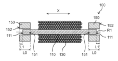
- FIG. 3 is a cross-sectional view showing a first example of the schematic configuration of the power generating element 100 according to the embodiment.
- FIG. 4 is a cross-sectional view showing a second example of the schematic configuration of the power generating element 100 according to the embodiment.
- FIGS. 3 and 4 show a cross-section taken along the arrangement direction, passing through the winding axis R1 of the coil 130.
- terminals 181, 182, and housing 190 are omitted from FIGS. 3 and 4. The same applies to the drawings of each power generating element described below.
- the power generating element 100 includes a magnetic member 110, a coil 130, and a magnetic collecting member 150.
- the magnetic member 110 is a magnetic member that generates the Large Barkhausen effect due to changes in the external magnetic field generated by the magnet 10 or the like.
- the magnetic member 110 is, for example, a composite magnetic wire such as a Wiegand wire, which has different magnetic properties in the radial center and outer periphery.
- a composite magnetic wire such as a Wiegand wire, which has different magnetic properties in the radial center and outer periphery.
- one of the central and outer periphery is a hard magnetic part, and the other is a soft magnetic part.
- the composite magnetic wire has magnetic properties in which the magnetization direction of the soft magnetic part changes with the application of a relatively small external magnetic field, whereas the magnetization direction of the hard magnetic part does not change unless a relatively large external magnetic field is applied.
- a relatively large external magnetic field sufficient to reverse the magnetization direction of the hard magnetic part of the composite magnetic wire is applied in the longitudinal direction of the composite magnetic wire, the magnetization direction of the hard magnetic part of the composite magnetic wire and the magnetization direction of the soft magnetic part are aligned in the same direction. Even if the direction of the external magnetic field applied to the composite magnetic wire is then reversed, the magnetization direction of the hard magnetic part and the magnetization direction of the soft magnetic part do not reverse while the external magnetic field is small due to the influence of the hard magnetic part.
- the magnetization direction of the soft magnetic part suddenly reverses when it exceeds a certain threshold value.
- This phenomenon in which the magnetic field suddenly reverses is also called a large Barkhausen jump. This causes a sudden change in the magnetic flux density of the composite magnetic wire, and power (power generation pulse) is generated in the coil 130 wound around the composite magnetic wire.
- the magnetic member 110 is not limited to a composite magnetic wire such as a Wiegand wire.
- the magnetic member 110 may be any magnetic member that has hard and soft magnetic parts with different magnetic properties and generates the Large Barkhausen effect.
- the hard and soft magnetic parts are arranged in a direction intersecting (for example, perpendicular to) the winding axis direction, and the hard and soft magnetic parts extend in the winding axis direction, thereby generating the Large Barkhausen effect.
- the magnetic member 110 may be a magnetic member having a structure in which thin films with different magnetic properties are stacked.
- the magnetic member 110 is, for example, a wire-like member extending along the winding axis direction of the coil 130.
- the cross-sectional shape of the magnetic member 110 cut in the radial direction is, for example, circular or elliptical. However, it may have other shapes such as rectangular or polygonal.
- the length of the magnetic member 110 is longer than the length of the coil 130.
- the coil 130 is a coil in which a conducting wire is wound around the magnetic member 110. Specifically, the coil 130 passes through the center of the magnetic member 110 and is wound along a winding axis R1 that extends in the longitudinal direction of the magnetic member 110. In the winding axis direction, the coil 130 is located between the two end faces 111 on both sides of the magnetic member 110. The coil 130 is located between the two magnetic collecting members 150. The coil 130 and the magnetic collecting members 150 are spaced apart. The coil 130 may be in contact with the magnetic collecting members 150 by increasing the number of turns and extending in the winding axis direction.
- the magnetic collecting member 150 is arranged at the end of the magnetic member 110 so as to be aligned with the coil 130 along the winding axis direction of the coil 130.
- two magnetic collecting members 150 are arranged, one at each end of the magnetic member 110.
- the two magnetic collecting members 150 face each other with the coil 130 in between.
- the two magnetic collecting members 150 have symmetrical shapes. In the following, mainly one of the two magnetic collecting members 150 will be described. However, the same description also applies to the other one.
- Fig. 5 is a plan view of the magnetic collecting member 150 according to the embodiment.
- Fig. 5 shows the planar shape of the magnetic collecting member 150 as seen from the outside along the winding axis direction.
- the magnetic collecting member 150 is a cylindrical member in which an opening 151 is formed.
- the length of the magnetic collecting member 150 in the winding axis direction is L0.
- the magnetic collecting member 150 is, for example, a ferrite bead made of a soft magnetic material such as ferrite.
- the magnetic collecting member 150 is provided to collect magnetic flux from the magnet 10 and to stabilize the magnetic flux in the magnetic member 110.
- the magnetic collecting member 150 is, for example, softer magnetic than the soft magnetic portion in the magnetic member 110. In other words, the magnetic collecting member 150 has a lower coercive force than the soft magnetic portion in the magnetic member 110.
- the magnetic collecting member 150 has an opening 151 into which a part of the magnetic member 110 is inserted.
- the opening 151 is a through hole that passes through the magnetic collecting member 150 along the winding axis direction.
- the opening 151 is located at the center of the magnetic collecting member 150 when viewed along the winding axis direction.
- the outer periphery of the magnetic collecting member 150 and the opening 151 each have a circular shape, for example. Therefore, the magnetic collecting member 150 is, for example, cylindrical.
- a portion of the magnetic member 110 near the end in the winding axis direction is located within the opening 151 and is covered by the magnetic collector 150.
- the outer end surface 152 of the magnetic collector 150 may be located outside the end surface 111 of the magnetic member 110 as shown in FIG. 3, or may be located inside the end surface 111 of the magnetic member 110 as shown in FIG. 4.
- the outer side in the winding axis direction refers to the direction away from the center of the magnetic member 110 in the winding axis direction.
- L1 >0
- the protruding length of the outer end surface 152 of the magnetic collector 150 from the end surface 111 of the magnetic member 110 to the outside is said to be L1 (>0).
- the length of the outer end surface 152 of the magnetic collector 150 protruding outward from the end surface 111 of the magnetic member 110 is said to be -L1 ( ⁇ 0). Details of the relative positions of the magnetic member 110 and the magnetic collector 150 will be described later.
- FIG. 6 is a schematic graph for explaining the jump height H0 of the power generating element 100 according to the embodiment.
- the graph in FIG. 6 is a hysteresis curve of the magnetization of the magnetic member 110.
- the horizontal axis of FIG. 6 indicates the external magnetic field strength applied to the power generating element 100.
- the vertical axis of FIG. 6 indicates the magnetization of the magnetic member 110.
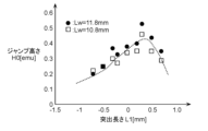
- Fig. 7 is a first graph showing the relationship between the projection length L1 of the power generating element 100 according to the embodiment and the jump height H0 of the power generating element 100.
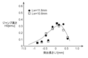
- Fig. 8 is a second graph showing the relationship between the projection length L1 of the power generating element 100 according to the embodiment and the jump height H0 of the power generating element 100.
- Fig. 9 is a third graph showing the relationship between the projection length L1 of the power generating element 100 according to the embodiment and the jump height H0 of the power generating element 100.
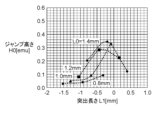
- FIG. 10 is a fourth graph showing the relationship between the projection length L1 of the power generating element 100 according to the embodiment and the jump height H0 of the power generating element 100.
- Fig. 11 is a fifth graph showing the relationship between the projection length L1 of the power generating element 100 according to the embodiment and the jump height H0 of the power generating element 100.
- 7, 8, and 9 show the relationship between the protrusion length L1 and the jump height H0 when the maximum value of the external magnetic field is 80 [Oe], 160 [Oe], and 200 [Oe], respectively.
- 7 to 9 show the relationship between the protrusion length L1 and the jump height H0 when the length Lw of the magnetic member 110 is 10.8 mm and 11.8 mm, and the curve (dotted line) that fits the relationship.
- 10 and 11 show the relationship between the protrusion length L1 and the jump height H0 when the maximum value of the external magnetic field is 80 [Oe] and 160 [Oe], respectively.
- 10 and 11 show the relationship between the protrusion length L1 and the jump height H0 when the length Lw of the magnetic member 110 is 10.8 mm and the length L0 in the winding axis direction of the magnetic flux collector member 150 is 0.8 mm, 1.0 mm, 1.2 mm, and 1.4 mm.
- the protruding length L1 of the magnetic collector 150 in the power generating element 100 is set as follows.
- the protruding length L1 of the magnetic collecting member 150 is -1% or more and 4% or less of the length Lw of the magnetic member 110.
- the protruding length L1 is, for example, approximately -0.1 mm or more and approximately 0.4 mm or less.
- a power generating element 100 with a large jump height H0 can be realized, as shown in Figures 7 to 9.
- the jump height H0 corresponds to the amount of power generated by the power generating element 100
- a power generating element 100 that can improve the amount of power generation can be realized.
- the protruding length L1 of the magnetic collecting member 150 may be greater than 0% and less than or equal to 3% of the length Lw of the magnetic member 110.
- the protruding length L1 may be, for example, greater than 0 mm and less than or equal to approximately 0.3 mm.
- the length L0 of the magnetic collector 150 in the winding axis direction may be 9% or more and 13% or less of the length Lw of the magnetic member 110 in the winding axis direction.
- the length of the magnetic collector 150 in the winding axis direction may be, for example, about 1.1 mm or more and about 1.4 mm or less.
- the jump height H0 of the power generating element 100 i.e., the amount of power generation, can be more reliably improved by setting the length L0 of the magnetic collector 150 in the winding axis direction to 9% or more of the length Lw of the magnetic member 110 in the winding axis direction.
- the length L0 of the magnetic collector 150 in the winding axis direction is set to 13% or less of the length Lw of the magnetic member 110 in the winding axis direction, thereby suppressing the jump height H0 of the power generating element 100, i.e., the decrease in the amount of power generated.
- the opening 151 of the magnetic collecting member 150 is a through hole.
- the opening 151 of the magnetic collecting member 150 may be a bottomed hole that does not penetrate through, with only the portion in the winding axis direction where the magnetic member 110 is inserted being open.
- a part of the magnetic collecting member 150 may also be disposed outside the end face 111 of the magnetic member 110.
- the end surface of the magnetic flux collecting member 150 in the winding axis direction has a planar shape perpendicular to the winding axis direction.
- the configuration of the magnetic flux collecting member 150 is not limited to this.
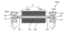
- Figure 12 is a cross-sectional view showing the general configuration of the power generating element 100a according to Modification 1.
- Figure 13 is a cross-sectional view showing the general configuration of the power generating element 100b according to Modification 2.
- Figure 14 is a cross-sectional view showing the general configuration of the power generating element 100c according to Modification 3.
- Figure 15 is a cross-sectional view showing the general configuration of the power generating element 100d according to Modification 4.
- the inner end surface of the magnetic collector 150b in the winding axis direction may have an inclined surface 158b that is inclined with respect to the winding axis direction, as in the magnetic collector 150b of the power generating element 100b according to the second modified example.
- the position of the inclined surface 158b in the winding axis direction approaches the outer end surface 152 of the magnetic collector 150b as it moves away from the winding axis R1.
- the inner end face of the magnetic flux collector 150c in the winding axis direction may have a recess 159c at the end on the winding axis R1 side.
- the power generating elements according to the above-described modifications 1 to 4 also achieve the same effects as the power generating element 100 according to the above-described embodiment.
- the position of the power generation element is fixed, and the magnet rotates due to the rotation of the rotating shaft, causing the direction of the magnetic field applied to the power generation element to repeatedly reverse.
- the configuration of the power generation system and encoder is not limited to this.
- the position of the magnet may be fixed, and the power generation element may rotate due to the rotation of the rotating shaft, causing the direction of the magnetic field applied to the power generation element to repeatedly reverse.
- a power generating element comprising a magnetic member that generates a large Barkhausen effect in response to a change in an external magnetic field, a coil wound around the magnetic member, and a magnetic collector arranged in line with the coil along the winding axis direction of the coil and having an opening through which a part of the magnetic member is inserted, the length of the outer end face of the magnetic collector protruding outward from the end face of the magnetic member in the winding axis direction being between -1% and 4% of the length of the magnetic member.
- a power generation system comprising a power generation element according to any one of technologies 1 to 6, and a magnetic field application unit that applies a magnetic field to the power generation element and repeatedly reverses the direction of the magnetic field applied to the power generation element, the power generation element generating power by reversing the direction of the magnetic field by the magnetic field application unit.
- the power generation element, power generation system, and encoder disclosed herein are useful for devices and equipment that rotate or move linearly, such as motors.
Landscapes
- Physics & Mathematics (AREA)
- General Physics & Mathematics (AREA)
- Transmission And Conversion Of Sensor Element Output (AREA)
Priority Applications (1)
| Application Number | Priority Date | Filing Date | Title |
|---|---|---|---|
| JP2025510069A JPWO2024202919A1 (https=) | 2023-03-28 | 2024-03-01 |
Applications Claiming Priority (2)
| Application Number | Priority Date | Filing Date | Title |
|---|---|---|---|
| JP2023050906 | 2023-03-28 | ||
| JP2023-050906 | 2023-03-28 |
Publications (1)
| Publication Number | Publication Date |
|---|---|
| WO2024202919A1 true WO2024202919A1 (ja) | 2024-10-03 |
Family
ID=92905564
Family Applications (1)
| Application Number | Title | Priority Date | Filing Date |
|---|---|---|---|
| PCT/JP2024/007703 Ceased WO2024202919A1 (ja) | 2023-03-28 | 2024-03-01 | 発電素子、発電システム、及びエンコーダ |
Country Status (2)
| Country | Link |
|---|---|
| JP (1) | JPWO2024202919A1 (https=) |
| WO (1) | WO2024202919A1 (https=) |
Citations (4)
| Publication number | Priority date | Publication date | Assignee | Title |
|---|---|---|---|---|
| US4287573A (en) * | 1978-08-07 | 1981-09-01 | Trw, Inc. | Method and means for coupling an elongated magnetic device |
| US20190148043A1 (en) * | 2016-04-08 | 2019-05-16 | Thomas Theil | Wiegand wire arrangement and method for the production thereof |
| WO2022230652A1 (ja) * | 2021-04-26 | 2022-11-03 | パナソニックIpマネジメント株式会社 | 発電素子、エンコーダ、磁性部材の製造方法および信号取得方法 |
| WO2022230651A1 (ja) * | 2021-04-26 | 2022-11-03 | パナソニックIpマネジメント株式会社 | 発電素子、エンコーダおよび磁性部材の製造方法 |
-
2024
- 2024-03-01 JP JP2025510069A patent/JPWO2024202919A1/ja active Pending
- 2024-03-01 WO PCT/JP2024/007703 patent/WO2024202919A1/ja not_active Ceased
Patent Citations (4)
| Publication number | Priority date | Publication date | Assignee | Title |
|---|---|---|---|---|
| US4287573A (en) * | 1978-08-07 | 1981-09-01 | Trw, Inc. | Method and means for coupling an elongated magnetic device |
| US20190148043A1 (en) * | 2016-04-08 | 2019-05-16 | Thomas Theil | Wiegand wire arrangement and method for the production thereof |
| WO2022230652A1 (ja) * | 2021-04-26 | 2022-11-03 | パナソニックIpマネジメント株式会社 | 発電素子、エンコーダ、磁性部材の製造方法および信号取得方法 |
| WO2022230651A1 (ja) * | 2021-04-26 | 2022-11-03 | パナソニックIpマネジメント株式会社 | 発電素子、エンコーダおよび磁性部材の製造方法 |
Also Published As
| Publication number | Publication date |
|---|---|
| JPWO2024202919A1 (https=) | 2024-10-03 |
Similar Documents
| Publication | Publication Date | Title |
|---|---|---|
| JP5108176B2 (ja) | 磁気感受性プローブ位置センサ | |
| CN101999079B (zh) | 具有铁磁元件的线性分段或转数计数器 | |
| JP7109713B1 (ja) | 発電素子、磁気センサ、エンコーダおよびモータ | |
| US20240312680A1 (en) | Power-generating element, encoder, and method for producing magnetic member | |
| JP7538927B2 (ja) | センサ | |
| JPWO2022230651A5 (https=) | ||
| US11994415B2 (en) | Encoder system for a drive | |
| WO2022230652A1 (ja) | 発電素子、エンコーダ、磁性部材の製造方法および信号取得方法 | |
| JPWO2022230652A5 (https=) | ||
| KR20060107516A (ko) | 자기식 인코더 장치 및 액츄에이터 | |
| WO2024202919A1 (ja) | 発電素子、発電システム、及びエンコーダ | |
| WO2023079838A1 (ja) | 発電素子、発電システムおよびエンコーダ | |
| WO2021020541A1 (ja) | 回転角度検出センサ | |
| JPWO2013008277A1 (ja) | 位置検出装置 | |
| WO2024190138A1 (ja) | パルス信号発生器およびエンコーダ | |
| JPH0515045B2 (https=) | ||
| WO2024075465A1 (ja) | 発電素子、発電システムおよびエンコーダ | |
| JPS63503496A (ja) | 電磁駆動装置 | |
| WO2024252862A1 (ja) | 複合磁性部材、発電素子、発電システムおよびエンコーダ | |
| CN224006579U (zh) | 电动致动器 | |
| CN111141316A (zh) | 磁编码器模块、磁编码器以及伺服电机 | |
| WO2024257402A1 (ja) | 発電素子、これを用いた磁気センサ及びエンコーダー | |
| JP2006074960A (ja) | 簡潔構造のモータ、及び、その始動方法 | |
| WO2026004170A1 (ja) | ロータリエンコーダ | |
| WO2018078847A1 (ja) | ロータリソレノイド |
Legal Events
| Date | Code | Title | Description |
|---|---|---|---|
| 121 | Ep: the epo has been informed by wipo that ep was designated in this application |
Ref document number: 24779057 Country of ref document: EP Kind code of ref document: A1 |
|
| WWE | Wipo information: entry into national phase |
Ref document number: 2025510069 Country of ref document: JP |
|
| NENP | Non-entry into the national phase |
Ref country code: DE |
|
| 122 | Ep: pct application non-entry in european phase |
Ref document number: 24779057 Country of ref document: EP Kind code of ref document: A1 |