WO2024202452A1 - ガスセンサ素子及びガスセンサ - Google Patents
ガスセンサ素子及びガスセンサ Download PDFInfo
- Publication number
- WO2024202452A1 WO2024202452A1 PCT/JP2024/001817 JP2024001817W WO2024202452A1 WO 2024202452 A1 WO2024202452 A1 WO 2024202452A1 JP 2024001817 W JP2024001817 W JP 2024001817W WO 2024202452 A1 WO2024202452 A1 WO 2024202452A1
- Authority
- WO
- WIPO (PCT)
- Prior art keywords
- gas sensor
- protective layer
- solid electrolyte
- electrolyte body
- sensor element
- Prior art date
- Legal status (The legal status is an assumption and is not a legal conclusion. Google has not performed a legal analysis and makes no representation as to the accuracy of the status listed.)
- Ceased
Links
Images








Classifications
-
- G—PHYSICS
- G01—MEASURING; TESTING
- G01N—INVESTIGATING OR ANALYSING MATERIALS BY DETERMINING THEIR CHEMICAL OR PHYSICAL PROPERTIES
- G01N27/00—Investigating or analysing materials by the use of electric, electrochemical, or magnetic means
- G01N27/26—Investigating or analysing materials by the use of electric, electrochemical, or magnetic means by investigating electrochemical variables; by using electrolysis or electrophoresis
- G01N27/403—Cells and electrode assemblies
- G01N27/406—Cells and probes with solid electrolytes
- G01N27/407—Cells and probes with solid electrolytes for investigating or analysing gases
- G01N27/4077—Means for protecting the electrolyte or the electrodes
-
- G—PHYSICS
- G01—MEASURING; TESTING
- G01N—INVESTIGATING OR ANALYSING MATERIALS BY DETERMINING THEIR CHEMICAL OR PHYSICAL PROPERTIES
- G01N27/00—Investigating or analysing materials by the use of electric, electrochemical, or magnetic means
- G01N27/26—Investigating or analysing materials by the use of electric, electrochemical, or magnetic means by investigating electrochemical variables; by using electrolysis or electrophoresis
- G01N27/403—Cells and electrode assemblies
- G01N27/406—Cells and probes with solid electrolytes
- G01N27/407—Cells and probes with solid electrolytes for investigating or analysing gases
- G01N27/409—Oxygen concentration cells
Definitions
- This disclosure relates to a gas sensor element and a gas sensor.
- a gas sensor element for detecting the concentration of a specific gas in a measured gas there is a laminated gas sensor element formed by laminating multiple ceramic layers including a solid electrolyte.
- a laminated gas sensor element as disclosed in Patent Document 1, there is one in which the tip of the element is covered with a porous protective layer. By providing such a protective layer, it is intended to trap poisonous substances in the measured gas and improve water resistance.
- stacked gas sensor elements with protective layers have the problem that it is difficult to stably ensure high measurement accuracy.
- the present disclosure aims to provide a gas sensor element and a gas sensor that can improve measurement accuracy.
- One aspect of the present disclosure is a solid electrolyte body having oxygen ion conductivity, a chamber facing the first surface of the solid electrolyte body and into which a gas to be measured is introduced; a chamber forming layer laminated on the first surface side of the solid electrolyte body to form the chamber; a duct facing the second surface of the solid electrolyte body and through which a reference gas is introduced; a duct forming layer formed on the second surface side of the solid electrolyte body to form the duct, At least a tip portion of the element located distal to the base end of the chamber is covered with a porous protective layer;
- the gas sensor element satisfies d/L ⁇ 1, where L is the thickness of the protective layer at the same position in the stacking direction as the solid electrolyte body, and d is the thickness of the solid electrolyte body.
- a gas sensor including the gas sensor element, a housing that holds the gas sensor element, and an element cover that is attached to a front end side of the housing and surrounds the gas sensor element from a front end side,
- the element cover is provided in the gas sensor and has an air hole at a position facing the chamber in the gas sensor element.
- the thickness L of the protective layer at the same stacking direction position as the solid electrolyte body and the thickness d of the solid electrolyte body satisfy d/L ⁇ 1. This makes it possible to improve the measurement accuracy of the gas sensor element.
- the gas sensor incorporates the gas sensor element that satisfies d/L ⁇ 1. This makes it possible to obtain a gas sensor with high measurement accuracy.
- the element cover also has an air hole at a position in the gas sensor element that faces the chamber. This makes it possible to effectively improve measurement accuracy.
- the above aspect provides a gas sensor element and a gas sensor that can improve measurement accuracy.
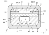
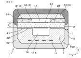
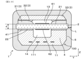
- FIG. 1 is a cross-sectional view of a gas sensor element according to a first embodiment, which is perpendicular to an X-direction and corresponds to a cross-section taken along line II in FIG.
- FIG. 2 is a cross-sectional view of the gas sensor element according to the first embodiment, which is perpendicular to the Y direction and corresponds to a cross-sectional view taken along line II-II in FIG.
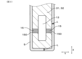
- FIG. 3 is a cross-sectional view taken along line III-III in FIG. 1;
- FIG. 1 is a cross-sectional view of a gas sensor element according to a first embodiment, which is perpendicular to an X-direction and corresponds to a cross-section taken along line II in FIG.
- FIG. 2 is a cross-sectional view of the gas sensor element according to the first embodiment, which is perpendicular to the Y direction and corresponds to a cross-sectional view taken along line II-II in FIG.
- FIG. 3 is a cross-
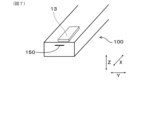
- FIG. 4 is a perspective view of a tip portion of a body portion of a gas sensor element according to the first embodiment
- FIG. 5 is a cross-sectional view taken along line V-V in FIG. 2
- FIG. 6 is a cross-sectional view perpendicular to the X-direction of a gas sensor element having a large thickness L.
- FIG. 7 is a perspective view of a tip portion of a body portion of a gas sensor element according to a second embodiment
- FIG. 8 is a cross-sectional view of a gas sensor element according to a second embodiment, the cross-sectional view being perpendicular to the Y direction
- FIG. 9 is a cross-sectional view of a chamber formation layer perpendicular to the Z direction in the second embodiment;
- FIG. 10 is a cross-sectional view of a gas sensor element according to a third embodiment, taken along a line perpendicular to the X-direction;
- FIG. 11 is a cross-sectional view of a gas sensor element according to a third embodiment, the cross-sectional view being perpendicular to the Y direction;
- FIG. 12 is a diagram showing test results in Experimental Example 1;
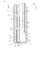
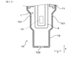
- FIG. 13 is a cross-sectional view of a portion of a gas sensor perpendicular to the Z direction in a fourth embodiment;
- FIG. 14 is an explanatory diagram of Sample 1 in Experimental Example 2;
- FIG. 15 is an explanatory diagram of Sample 3 in Experimental Example 2;
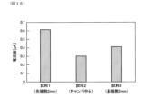
- FIG. 16 is a diagram showing test results in Experimental Example 2;
- FIG. 14 is an explanatory diagram of Sample 1 in Experimental Example 2;
- FIG. 15 is an explanatory diagram of Sample 3 in Experimental Example 2;
- FIG. 16 is a diagram showing test results in Experimental Example 2;
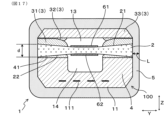
- FIG. 17 is a cross-sectional view of a gas sensor element in a first modified embodiment, the cross-sectional view being perpendicular to the X-direction;
- FIG. 18 is a cross-sectional view of a gas sensor element in a second modified embodiment, the cross-sectional view being perpendicular to the X-direction;
- FIG. 19 is a cross-sectional view of the gas sensor element in the third modified embodiment, taken along a line perpendicular to the X direction.
- the gas sensor element 1 of this embodiment includes a solid electrolyte body 2, a chamber 13, a chamber forming layer 3, a duct 14, and a duct forming layer 4. As shown in FIG. 1 and 2, the gas sensor element 1 of this embodiment includes a solid electrolyte body 2, a chamber 13, a chamber forming layer 3, a duct 14, and a duct forming layer 4. As shown in FIG. 1
- the solid electrolyte body 2 has oxygen ion conductivity.
- the chamber 13 faces the first surface 21 of the solid electrolyte body 2 and is a space into which the gas to be measured is introduced.
- the chamber forming layer 3 is laminated on the first surface 21 side of the solid electrolyte body 2 to form the chamber 13.
- the duct 14 faces the second surface 22 of the solid electrolyte body 2 and is a space into which the reference gas is introduced.
- the duct forming layer 4 is laminated on the second surface 22 side of the solid electrolyte body 2 to form the duct 14.
- At least the tip of the element which is closer to the tip than the base end of the chamber 13, is covered with a porous protective layer 5.
- a porous protective layer 5 In this embodiment of the gas sensor element 1, when the thickness of the protective layer 5 at the same stacking direction position as the solid electrolyte body 2 is L and the thickness of the solid electrolyte body 2 is d, the relationship d/L ⁇ 1 is satisfied.
- the gas sensor element 1 of this embodiment is a laminated gas sensor element in which a plurality of ceramic layers are laminated.
- a sensor electrode 61 and a reference gas side electrode 62 are formed on one side (i.e., the first side 21) and the other side (i.e., the second side 22) of a plate-shaped solid electrolyte body 2, respectively.
- the sensor electrode 61 and the reference gas side electrode 62 are arranged opposite each other via a part of the solid electrolyte body 2.
- a sensor cell is formed by the sensor electrode 61, the reference gas side electrode 62, and a portion of the solid electrolyte body 2 between the sensor electrode 61 and the reference gas side electrode 62.
- the sensor electrode 61 is active against a specific gas in the measured gas.
- the measured gas is exhaust gas from an internal combustion engine, and the specific gas is oxygen.
- the sensor electrode 61 active against oxygen contains, for example, platinum (Pt) and gold (Au) or rhodium (Rh).
- the gas sensor element 1 is formed by laminating the chamber forming layer 3 on the first surface 21 of the solid electrolyte body 2.
- the chamber forming layer 3 is composed of buffer layers 31, 32 and a shielding layer 33, which are sequentially laminated on the first surface 21 of the solid electrolyte body 2.
- the duct forming layer 4 is laminated on the second surface 22 of the solid electrolyte body 2 via a buffer layer 41.
- the buffer layer 41 is also a part of the duct forming layer 4 that forms the duct 14, but in this embodiment, the portion excluding the buffer layer 41 may be referred to as the duct forming layer 4.
- the heater layer 11 is laminated on the surface of the duct forming layer 4 opposite the solid electrolyte body 2.
- the heater wiring 111 is formed between the heater layer 11 and the duct forming layer 4.
- the heater layer 11 and the duct forming layer 4 may be integrated, and there may be no particular boundary between them.
- the stacking direction in which multiple ceramic layers are stacked is referred to as the Z direction, where appropriate.
- the gas sensor element 1 has a long plate rod shape in one direction perpendicular to the Z direction.
- the longitudinal direction of this gas sensor element 1 is referred to as the X direction, where appropriate.
- the direction perpendicular to both the X direction and the Z direction is referred to as the Y direction, where appropriate.
- the chamber 13 when viewed from the Z direction, the chamber 13 is surrounded by the buffer layers 31 and 32, but a porous diffusion layer 15 is disposed on a part of the outer periphery of the chamber 13.
- the diffusion layers 15 are disposed on both sides of the chamber 13 in the Y direction. This allows the measurement gas to be introduced into the chamber 13 from both sides in the Y direction through the diffusion layers 15. That is, as shown in FIG. 3, FIG. 4, and FIG. 5, the measurement gas inlet 150 to the chamber 13 is provided on the side of the body 100 of the gas sensor element 1 facing both sides in the Y direction.
- the body 100 means the gas sensor element 1 in a state in which the protective layer 5 is not formed, and FIG. 4 shows a perspective view of the tip of the body 100.
- the chamber 13 has a shape that is longer in the X direction than in the Y direction.
- the solid electrolyte body 2 is a ceramic layer whose main component is zirconia.
- the shielding layer 33, the duct forming layer 4, and the heater layer 11 are all ceramic layers whose main component is alumina.
- the diffusion layer 15 also has alumina as its main component.
- the diffusion layer 15 is made of a porous ceramic body that allows the measured gas to pass through.
- the solid electrolyte body 2, the shielding layer 33, the duct forming layer 4, the heater layer 11, and the buffer layers 31, 32, and 41 are made of dense ceramic bodies that do not allow gas to pass through.
- the buffer layers 31 and 32 are made of a material that has a linear expansion coefficient between that between the solid electrolyte body 2 and the shielding layer 33.
- the buffer layer 41 is made of a material that has a linear expansion coefficient between that between the solid electrolyte body 2 and the duct forming layer 4.
- the buffer layers 31, 32, and 41 contain alumina and zirconia.
- the protective layer 5 is made of porous ceramic.
- the porous ceramic forming the protective layer 5 is made of alumina.
- the protective layer 5 is formed so as to cover the entire circumference of the tip portion of the element and the tip surface.
- the thickness L of the protective layer 5 is less than or equal to the thickness d of the solid electrolyte body 2.
- the thickness of the protective layer 5 at the portions covering the Y-direction side surfaces of the gas sensor element 1 is approximately constant, and the thickness L is equal to or less than the thickness d of the solid electrolyte body 2.
- the thickness of the portion covering the tip surface of the gas sensor element 1 is also approximately constant, and the thickness L is equal to or less than the thickness d of the solid electrolyte body 2.
- the thickness L of each of the protective layers 5 on both sides of the gas sensor element 1 in the Y direction and the thickness L of the protective layer 5 at the tip surface of the element all satisfy d/L ⁇ 1.
- the inlet 150 for the gas to be measured is provided on the side surface facing the Y direction. Therefore, considering the inflow route of the reference gas leaking from the duct 14 from the inlet 150 through the diffusion layer 15 into the chamber 13, it is considered more important to reduce the thickness L of each of the protective layers 5 on both sides of the gas sensor element 1 in the Y direction. Therefore, it is also possible to make the thickness L of the protective layer 5 on both sides of the gas sensor element 1 in the Y direction smaller than the thickness L of the protective layer 5 at the tip surface of the element.
- the thickness L of the protective layer 5 can be, for example, 10 to 400 ⁇ m.
- the porosity of the protective layer 5 can be, for example, 20 to 70%.
- a ceramic green sheet to become the solid electrolyte body 2 a ceramic green sheet to become the shielding layer 33, a ceramic green sheet to become the duct forming layer 4, a ceramic green sheet to become the heater layer 11, and a ceramic green sheet for the diffusion layer 15 are prepared.
- the diffusion layer 15 can also be formed by printing a ceramic paste instead of using the ceramic green sheets.
- the ceramic green sheets for the duct forming layer 4 and the ceramic green sheets for the heater layer 11 are laminated together. Prior to this lamination, a conductive paste for heater wiring is printed on the heater layer 11.
- the duct forming layer 4 can also be formed by laminating multiple ceramic green sheets.
- the laminated and integrated ceramic green sheets for the duct forming layer 4 and the heater layer 11 are hereinafter referred to as the duct side laminated sheet, as appropriate.
- the sensor electrode 61 and the reference gas side electrode 62 are formed with conductive paste on the first surface 21 and the second surface 22 of the ceramic green sheet that will become the solid electrolyte body 2.
- the ceramic paste that will become the buffer layer 31 is applied to a predetermined position on the first surface 21 of the ceramic green sheet that will become the solid electrolyte body 2.
- a ceramic green sheet for the diffusion layer 15 is placed (or ceramic paste for the diffusion layer 15 is printed) at a predetermined position on the surface of the ceramic green sheet that will become the shielding layer 33 that faces the solid electrolyte body 2, and the ceramic paste that will become the buffer layer 32 is applied.
- the ceramic green sheet for the shielding layer 33 to which the ceramic paste has been applied is laminated and pressure-bonded to the first surface 21 of the ceramic green sheet for the solid electrolyte body 2.
- a ceramic paste that will become the buffer layer 41 is applied to a predetermined position on the surface of the duct side laminate sheet that faces the solid electrolyte body 2.
- the duct side laminate sheet to which this ceramic paste has been applied is laminated and pressed onto the second surface 22 of the ceramic green sheet for the solid electrolyte body 2.
- the laminate in this state is fired to form the main body 100 of the gas sensor element 1.
- the tip of the body 100 of the gas sensor element 1 is immersed in a ceramic slurry for forming the protective layer 5. This causes the ceramic slurry to adhere to the tip of the gas sensor element 1. The adhered ceramic slurry is then dried and fired to form the protective layer 5.
- the thickness L of the protective layer 5 can be controlled, for example, by adjusting the viscosity of the ceramic slurry, the surface tension, the average particle size of the ceramic powder, etc.
- the gas sensor element 1 of this embodiment is built into a gas sensor that is attached to the exhaust system of an internal combustion engine, for example. Exhaust gas as the gas to be measured is introduced into the chamber 13, and air as the reference gas is introduced into the duct 14. When a predetermined voltage is applied to the sensor cell, a predetermined current flows according to the difference in oxygen concentration between the duct 14 and the chamber 13. In a certain applied voltage range, there is almost no change in the output current value even if the applied voltage changes. This current is called the limit current. The oxygen concentration in the exhaust gas can be detected based on this limit current value. In this way, the gas sensor element 1 of this embodiment can be used as an element of a so-called limit current type air-fuel ratio sensor.
- the protective layer 5 also has a function of trapping, for example, poisonous substances present in the exhaust gas. This makes it possible to prevent the poisonous substances from entering the chamber 13.
- the protective layer 5 also has a function of suppressing cracking due to water.
- moisture present in the exhaust gas pipe may fly to the gas sensor element 1 along with the exhaust gas.
- the presence of the protective layer 5 makes it possible to prevent moisture from adhering directly to the main body 100 of the element. This makes it possible to suppress element cracking caused by stress generated by the adhesion of moisture (i.e., cracking due to water).
- the thickness L of the protective layer 5 at the same position in the stacking direction as the solid electrolyte body 2 and the thickness d of the solid electrolyte body 2 satisfy d/L ⁇ 1. This makes it possible to improve the measurement accuracy of the gas sensor element 1.
- the measurement gas is exhaust gas
- the reference gas is air
- the specific gas is oxygen.
- the solid electrolyte body 2 and the duct forming layer 4 are in close contact with each other.
- the thickness L of the protective layer 5 is large, oxygen is likely to remain in the protective layer 5. It is possible that some of the oxygen remaining in the protective layer 5 moves within the protective layer 5 and enters the chamber 13. In other words, it is difficult to achieve a completely airtight seal between the solid electrolyte body 2 and the chamber forming layer 3 (i.e., the buffer layers 31, 32, and the shielding layer 33) due to differences in materials. Therefore, it is similarly difficult to avoid the intrusion of oxygen from the protective layer 5 into the chamber 13. In addition, if some of the oxygen reaches the inlet 150 through the protective layer 5, it is possible that some of the oxygen will enter the chamber 13 through the diffusion layer 15.
- the oxygen concentration in the exhaust gas is essentially zero, but when the above phenomenon occurs, oxygen is detected by the gas sensor.
- the output current of the gas sensor should be zero, but it is not zero and some current is output. This leads to measurement errors.
- the thickness L of the protective layer 5 at the same stacking direction position as the solid electrolyte body 2 is set to satisfy d/L ⁇ 1 in relation to the thickness d of the solid electrolyte body 2.
- the thickness d of the solid electrolyte body 2 when the thickness d of the solid electrolyte body 2 is small, some of the oxygen that leaks from the duct 14 to the protective layer 5 on the second surface 22 side is likely to move toward the first surface 21 side. This means that some of the oxygen that leaks into the protective layer 5 is likely to infiltrate into the chamber 13. On the other hand, when the thickness d of the solid electrolyte body 2 is large, some of the oxygen that leaks from the duct 14 to the protective layer 5 on the second surface 22 side moves a larger distance toward the first surface 21 side. Therefore, the oxygen that leaks into the protective layer 5 is less likely to infiltrate into the chamber 13.
- the thickness d is large and the thickness L is small.
- the inventors of the present application have found that when d/L ⁇ 1 is satisfied, the above phenomenon can be suppressed and the detection error of the gas sensor can be sufficiently suppressed. The experimental results will be described later.
- this embodiment provides a gas sensor element that can improve measurement accuracy.
- this embodiment is a gas sensor element 1 having an exhaust gas inlet 150 at the tip end face of the element. That is, the gas sensor element 1 of this embodiment is provided with the diffusion layer 15 on the tip side of the chamber 13. As a result, an inlet 150 is disposed on the tip surface of the element.
- the thickness L of the protective layer 5 (see Figures 1, 8, and 9) satisfies d/L ⁇ 1.
- the exhaust gas inlet 150 is provided on the tip surface. Therefore, when considering the inflow route of oxygen leaking from the duct 14 from the inlet 150 through the diffusion layer 15 into the chamber 13, it is considered more important to reduce the thickness L of the protective layer 5 at the tip surface. Therefore, it is also possible to make the thickness L of the protective layer 5 at the tip surface of the element smaller than the thickness L of the protective layer 5 on both sides of the gas sensor element 1 in the Y direction.
- this embodiment is a gas sensor element 1 in which the protective layer 5 has a first protective layer 51 and a second protective layer 52.
- the first protective layer 51 is formed at a position including at least the boundary between the solid electrolyte body 2 and the chamber forming layer 3.
- the second protective layer 52 is formed at a position including at least the boundary between the solid electrolyte body 2 and the duct forming layer 4.
- the first protective layer 51 is formed to cover a part of the solid electrolyte body 2 and the chamber forming layer 3 (i.e., the buffer layers 31, 32, and the shielding layer 33).
- the second protective layer 52 is formed to cover a part of the solid electrolyte body 2, the duct forming layer 4, and the heater layer 11.
- the porosity of the second protective layer 52 is higher than the porosity of the first protective layer 51.
- the porosity of the first protective layer 51 is 20 to 40 volume %, and the porosity of the second protective layer 52 is 40 to 70 volume %. The rest is the same as in the first embodiment.
- oxygen leaking from duct 14 first reaches second protective layer 52. Since second protective layer 52 has a relatively high porosity, the leaking oxygen is easily discharged to the outside of protective layer 5. On the other hand, since first protective layer 51 has a relatively low porosity, oxygen is unlikely to move from second protective layer 52 to first protective layer 51. Therefore, oxygen leaking from duct 14 can be effectively prevented from entering chamber 13.
- the porosity of the first protective layer 51 is 20 to 40 vol. %, and the porosity of the second protective layer 52 is 40 to 70 vol. %.
- the porosity of the second protective layer 52 is higher than the porosity of the first protective layer 51, and the porosity of the first protective layer 51 is 40 vol. % or less, and the porosity of the second protective layer 52 is 40 vol. % or more, so that the above-mentioned effect is easier to obtain.
- the porosity of the first protective layer 51 is less than 20 vol. %, it may be difficult to sufficiently introduce the measurement gas (exhaust gas) into the chamber 13.
- the porosity of the second protective layer 52 exceeds 70 vol. %, it may be difficult to sufficiently enhance the poisoning substance trapping effect and the water crack suppression effect of the protective layer 5.
- the second embodiment has the same effects as the first embodiment.
- Example 1 In this example, as shown in FIG. 12, the relationship between the thickness L of the protective layer on the side surface of the gas sensor element and the measurement accuracy of the gas sensor element was examined.
- the gas sensor element used as the sample had the same basic structure as that shown in embodiment 2. However, several types were produced with different thicknesses L of the protective layer 5 on the side surface.
- the thickness L of the protective layer 5 on the tip surface was 100 ⁇ m in all samples.
- the thickness d of the solid electrolyte body 2 was 160 ⁇ m.
- the gas sensor element was heated to its activation temperature by passing electricity through the heater built into the element. In this state, the current value flowing through the sensor cell when a certain voltage was applied to the sensor cell, i.e., the limiting current value, was measured.
- the gas to be measured is nitrogen gas, which corresponds to a stoichiometric gas, so ideally the limiting current value should be zero.
- some samples output a current.
- the thickness L of the protective layer 5 exceeded 160 ⁇ m, i.e., the thickness d of the solid electrolyte body 2 exceeded, a noise current was detected. It was also confirmed that the larger the thickness L, the larger the noise current. As described above, this noise current is presumably due to some of the oxygen leaking from the duct 14 entering the chamber 13.
- this embodiment is a gas sensor 10 including a gas sensor element 1.
- the gas sensor 10 has a gas sensor element 1, a housing 71, and an element cover 72.
- the housing 71 holds the gas sensor element 1.
- the element cover 72 is attached to the tip side of the housing 71 and surrounds the gas sensor element 1 from the tip side.
- the element cover 72 has an air hole 721 at a position facing the chamber 13 in the gas sensor element 1.
- the housing 71 holds the gas sensor element 1 directly or indirectly.
- the gas sensor element 1 is held via an insulator (not shown).
- the air hole 721 faces the chamber 13 via the protective layer 5 or the like.
- the position of the gas sensor element 1 facing the chamber 13 means the position in the X direction that overlaps with the chamber 13.
- the ventilation hole 721 overlaps with at least a portion of the chamber 13.
- the center of the ventilation hole 721 overlaps with the chamber 13.
- the entire ventilation hole 721 is included in the formation area of the chamber 13 in the X direction.
- a portion or the entire ventilation hole 721 overlaps with the position of the diffusion layer 15 in the X direction.
- the element cover 72 also has an air vent 722 at the tip. As shown in FIG. 13, exhaust gas G introduced into the element cover 72 from the side air vent 721 is exhausted from the air vent 722 at the tip. Meanwhile, part of the exhaust gas G is introduced into the chamber 13 of the gas sensor element 1.
- the vent hole 721 is formed at a position facing the gas sensor element 1 in the Y direction.
- the configuration of the gas sensor element 1 is the same as that of embodiment 1. Therefore, the diffusion layer 15 is formed on both sides of the chamber 13 in the Y direction (see FIGS. 3 to 5).
- the exhaust gas G flowing in through the vent hole 721 of the element cover 72 collides with a position in the vicinity of the chamber 13 in the gas sensor element 1. Then, a sufficient flow rate of the exhaust gas G passes through the protective layer 5 in the vicinity of the chamber 13. Then, oxygen leaking from the duct 14 is easily discharged from the protective layer 5 along with the flow of the exhaust gas G. Therefore, it is possible to prevent oxygen from accumulating in the protective layer 5 in the vicinity of the chamber 13, and effectively prevent oxygen from entering the chamber 13.
- the second embodiment has the same effects as the first embodiment.
- the element cover 72 can have a double or more layer structure.
- the vent hole in the innermost element cover i.e., the element cover closest to the gas sensor element 1
- the vent hole 721 that satisfies the above-mentioned X-direction position.
- Example 2 In this example, as shown in FIG. 16, the relationship between the position of the vent hole 721 in the X direction and the measurement accuracy of the gas sensor element was examined.
- the gas sensor element used as the sample had the same basic structure as that shown in embodiment 4.
- the thickness L of the protective layer 5 was 400 ⁇ m in all samples, which does not satisfy d/L ⁇ 1. Therefore, all samples are different from embodiment 4. This is because, in order to make it easier to understand the effect of the position of the air vent 721, the structure of the gas sensor element itself is disadvantageous in terms of suppressing oxygen intrusion into the chamber 13.
- the structure of the gas sensor element was the same as embodiment 1, except for the thickness L of the protective layer.
- sample 1 was prepared with the center position of the vent hole 721 set 2 mm toward the tip side of the center of the chamber 13.
- sample 2 was prepared with the center position of the vent hole 721 set at the same X-direction position as the center of the chamber 13.
- sample 3 was prepared with the center position of the vent hole 721 set 2 mm toward the base side of the center of the chamber 13. The length of the chamber 13 in the X-direction was set to 3.4 mm.
- samples 2 and 3 are able to suppress noise currents compared to sample 1.
- the noise current is particularly small in sample 2 it is believed that a greater effect can be obtained by locating the vent 721 in a position facing the center of the chamber 13 in the X direction.
- gas sensor element and gas sensor disclosed herein are not limited to the gas sensor element and gas sensor shown in the above embodiment, and various configurations are possible.
- the thickness of the solid electrolyte body 2 can be different at the center and both ends in the Y direction.
- the thickness d of the solid electrolyte body 2 is defined as the thickness at the ends.
- the oxygen that enters the chamber 13 is oxygen that has leaked from the duct 14 to the protective layer 5. Taking this into consideration, it is clear that the parameter related to suppressing oxygen intrusion into the chamber 13 is not the thickness of the solid electrolyte body 2 at the center, but the thickness at the ends. Therefore, in the case of a structure such as that shown in FIG. 17, the thickness d of the solid electrolyte body 2 is defined as the thickness at the ends.
- a recess 53 may be provided in the protective layer 5 at a Z-direction position where the protective layer 5 overlaps the solid electrolyte body 2.
- the recess 53 extends in the X-direction at least to the extent of covering the region where the chamber 13 is formed. This allows the thickness L of the protective layer 5 at the same Z-direction position as the solid electrolyte body 2 to be small, while the thickness of the protective layer 5 at other locations to be large. Since it is the small thickness L of the protective layer 5 at the Z-direction position where the protective layer 5 overlaps the solid electrolyte body 2 that contributes to the suppression of oxygen intrusion into the chamber 13, the thickness L of this portion is made small so as to satisfy d/L ⁇ 1. On the other hand, by making the thickness of the protective layer 5 at other locations large, it is possible to improve functions such as trapping poisonous substances and suppressing water-resistant cracking.
- the solid electrolyte body 2 can be configured to protrude in the Y direction further than other parts of the body 100 of the gas sensor element 1.
- the thickness L of the protective layer 5 at the same Z direction position as the solid electrolyte body 2 can be made smaller, while the thickness of the protective layer 5 at other locations can be made larger.
- the diffusion layer 15 is not in contact with the sensor electrode 61, but this is not a particular limitation.
- the chamber 13 may be filled with a porous diffusion layer, and the sensor electrode 61 may be in contact with the diffusion layer.
- the gas sensor element satisfies d/L ⁇ 1, where L is the thickness of the protective layer at the same position in the stacking direction as the solid electrolyte body, and d is the thickness of the solid electrolyte body.
- the protective layer includes a first protective layer (51) formed at a position including at least a boundary between the solid electrolyte body and the chamber forming layer, and a second protective layer (52) formed at a position including at least a boundary between the solid electrolyte body and the duct forming layer, and the porosity of the second protective layer is higher than the porosity of the first protective layer.
- a gas sensor (10) comprising the gas sensor element according to any one of [1] to [4], a housing (71) for holding the gas sensor element, and an element cover (72) attached to a front end side of the housing and surrounding the gas sensor element from a front end side, The gas sensor, wherein the element cover has an air hole (721) at a position facing the chamber in the gas sensor element.
Landscapes
- Chemical & Material Sciences (AREA)
- Life Sciences & Earth Sciences (AREA)
- Health & Medical Sciences (AREA)
- Physics & Mathematics (AREA)
- Chemical Kinetics & Catalysis (AREA)
- Electrochemistry (AREA)
- Molecular Biology (AREA)
- Analytical Chemistry (AREA)
- Biochemistry (AREA)
- General Health & Medical Sciences (AREA)
- General Physics & Mathematics (AREA)
- Immunology (AREA)
- Pathology (AREA)
- Measuring Oxygen Concentration In Cells (AREA)
Abstract
Description
該固体電解質体における第1面に面し、被測定ガスが導入されるチャンバと、
上記固体電解質体における第1面側に積層されて、上記チャンバを形成するチャンバ形成層と、
上記固体電解質体における第2面に面し、基準ガスが導入されるダクトと、
上記固体電解質体における第2面側に積層されて、上記ダクトを形成するダクト形成層と、を有するガスセンサ素子であって、
少なくとも上記チャンバの基端よりも先端側の素子先端部は、多孔質の保護層によって覆われており、
上記固体電解質体と同じ積層方向位置における上記保護層の厚みをL、上記固体電解質体の厚みをd、としたとき、d/L≧1を満たす、ガスセンサ素子にある。
上記素子カバーは、上記ガスセンサ素子における上記チャンバと対向する位置に、通気孔を有する、ガスセンサにある。
ガスセンサ素子及びガスセンサに係る実施形態について、図1~図5を参照して説明する。
本形態のガスセンサ素子1は、図1、図2に示すごとく、固体電解質体2と、チャンバ13と、チャンバ形成層3と、ダクト14と、ダクト形成層4と、を有する。
まず、固体電解質体2となるセラミックグリーンシートと、遮蔽層33となるセラミックグリーンシートと、ダクト形成層4となるセラミックグリーンシートと、ヒータ層11となるセラミックグリーンシートと、拡散層15用のセラミックグリーンシートとを用意する。なお、拡散層15は、セラミックグリーンシートではなく、セラミックペーストの印刷にて形成することもできる。
上記ガスセンサ素子1においては、固体電解質体2と同じ積層方向位置における保護層5の厚みLと、固体電解質体2の厚みdとが、d/L≧1を満たす。これにより、ガスセンサ素子1の測定精度の向上を図ることができる。以下において、そのメカニズムにつき、説明する。なお、以下においては、被測定ガスを排ガス、基準ガスを大気、特定ガスを酸素として、説明する。
本形態は、図7~図9に示すごとく、排ガスの導入口150を素子先端面に設けたガスセンサ素子1の形態である。
すなわち、本形態のガスセンサ素子1は、チャンバ13の先端側に、拡散層15を設けている。これにより、素子先端面に導入口150が配置される。
本形態も、実施形態1と同様の作用効果を有する。
本形態は、図10、図11に示すごとく、保護層5が、第1保護層51と第2保護層52とを有する、ガスセンサ素子1の形態である。
第1保護層51は、少なくとも固体電解質体2とチャンバ形成層3との境界を含む位置に形成されている。第2保護層52は、少なくとも固体電解質体2とダクト形成層4との境界を含む位置に形成されている。
その他は、実施形態1と同様である。
その他、実施形態1と同様の作用効果を有する。
本例は、図12に示すごとく、ガスセンサ素子の側面における保護層の厚みLと、ガスセンサ素子の測定精度との関係を調べた例である。
まず、排ガス流れを模したモデルガスベンチ内に、ガスセンサ素子を備えたガスセンサを設置した。モデルガスベンチには、排ガスの代わりに窒素ガスを流した。つまり、ストイキの排ガスと同様に、酸素濃度が実質的にゼロとなる窒素ガスを流した。
上述のように、本例では、被測定ガスが窒素ガスであり、ストイキガスに相当するため、理想的には、限界電流値はゼロとなるはずである。ところが、図12に示すように、電流が出力されるものもあった。保護層5の厚みLが160μmを超えるもの、すなわち、固体電解質体2の厚みdを超える試料については、ノイズ電流が検出された。そして、厚みLが大きくなるほど、ノイズ電流が大きくなることも確認された。このノイズ電流は、上述したように、ダクト14から漏れ出た酸素の一部がチャンバ13に侵入したことによるものと推測される。
本形態は、図13に示すごとく、ガスセンサ素子1を備えたガスセンサ10の形態である。
ガスセンサ素子1の構成については、実施形態1と同様である。それゆえ、拡散層15は、チャンバ13のY方向の両側に形成されている(図3~図5参照)。
その他、実施形態1と同様の作用効果を有する。
本例は、図16に示すごとく、X方向における通気孔721の位置と、ガスセンサ素子の測定精度との関係を調べた例である。
実験例1と同様のモデルガスベンチに、ガスセンサを設置して、同様に限界電流値を測定した。その結果を、図16に示す。
[1] 酸素イオン伝導性を有する固体電解質体(2)と、
該固体電解質体における第1面(21)に面し、被測定ガスが導入されるチャンバ(13)と、
上記固体電解質体における第1面側に積層されて、上記チャンバを形成するチャンバ形成層(3)と、
上記固体電解質体における第2面(22)に面し、基準ガスが導入されるダクト(14)と、
上記固体電解質体における第2面側に積層されて、上記ダクトを形成するダクト形成層(4)と、を有するガスセンサ素子(1)であって、
少なくとも上記チャンバの基端よりも先端側の素子先端部は、多孔質の保護層(5)によって覆われており、
上記固体電解質体と同じ積層方向位置における上記保護層の厚みをL、上記固体電解質体の厚みをd、としたとき、d/L≧1を満たす、ガスセンサ素子。
[2] 上記保護層の厚みLと上記固体電解質体の厚みdとは、d/L≧2を満たす、[1]に記載のガスセンサ素子。
[3] 上記保護層は、少なくとも上記固体電解質体と上記チャンバ形成層との境界を含む位置に形成された第1保護層(51)と、少なくとも上記固体電解質体と上記ダクト形成層との境界を含む位置に形成された第2保護層(52)と、を有し、上記第1保護層の気孔率よりも、上記第2保護層の気孔率が高い、[1]又は[2]に記載のガスセンサ素子。
[4] 上記第1保護層の気孔率は20~40体積%であり、上記第2保護層の気孔率は40~70体積%である、[3]に記載のガスセンサ素子。
[5] [1]~[4]のいずれかに記載のガスセンサ素子と、該ガスセンサ素子を保持するハウジング(71)と、該ハウジングの先端側に取り付けられ、上記ガスセンサ素子を先端側から囲む素子カバー(72)とを有する、ガスセンサ(10)であって、
上記素子カバーは、上記ガスセンサ素子における上記チャンバと対向する位置に、通気孔(721)を有する、ガスセンサ。
Claims (5)
- 酸素イオン伝導性を有する固体電解質体(2)と、
該固体電解質体における第1面(21)に面し、被測定ガスが導入されるチャンバ(13)と、
上記固体電解質体における第1面側に積層されて、上記チャンバを形成するチャンバ形成層(3)と、
上記固体電解質体における第2面(22)に面し、基準ガスが導入されるダクト(14)と、
上記固体電解質体における第2面側に積層されて、上記ダクトを形成するダクト形成層(4)と、を有するガスセンサ素子(1)であって、
少なくとも上記チャンバの基端よりも先端側の素子先端部は、多孔質の保護層(5)によって覆われており、
上記固体電解質体と同じ積層方向位置における上記保護層の厚みをL、上記固体電解質体の厚みをd、としたとき、d/L≧1を満たす、ガスセンサ素子。 - 上記保護層の厚みLと上記固体電解質体の厚みdとは、d/L≧2を満たす、請求項1に記載のガスセンサ素子。
- 上記保護層は、少なくとも上記固体電解質体と上記チャンバ形成層との境界を含む位置に形成された第1保護層(51)と、少なくとも上記固体電解質体と上記ダクト形成層との境界を含む位置に形成された第2保護層(52)と、を有し、上記第1保護層の気孔率よりも、上記第2保護層の気孔率が高い、請求項1又は2に記載のガスセンサ素子。
- 上記第1保護層の気孔率は20~40体積%であり、上記第2保護層の気孔率は40~70体積%である、請求項3に記載のガスセンサ素子。
- 請求項1又は2に記載のガスセンサ素子と、該ガスセンサ素子を保持するハウジング(71)と、該ハウジングの先端側に取り付けられ、上記ガスセンサ素子を先端側から囲む素子カバー(72)とを有する、ガスセンサ(10)であって、
上記素子カバーは、上記ガスセンサ素子における上記チャンバと対向する位置に、通気孔(721)を有する、ガスセンサ。
Priority Applications (3)
| Application Number | Priority Date | Filing Date | Title |
|---|---|---|---|
| JP2025509800A JP7776042B2 (ja) | 2023-03-24 | 2024-01-23 | ガスセンサ素子及びガスセンサ |
| DE112024001392.9T DE112024001392T5 (de) | 2023-03-24 | 2024-01-23 | Gassensorelement und gassensor |
| US19/337,151 US20260023044A1 (en) | 2023-03-24 | 2025-09-23 | Gas sensor element and gas sensor |
Applications Claiming Priority (2)
| Application Number | Priority Date | Filing Date | Title |
|---|---|---|---|
| JP2023047901 | 2023-03-24 | ||
| JP2023-047901 | 2023-03-24 |
Related Child Applications (1)
| Application Number | Title | Priority Date | Filing Date |
|---|---|---|---|
| US19/337,151 Continuation US20260023044A1 (en) | 2023-03-24 | 2025-09-23 | Gas sensor element and gas sensor |
Publications (1)
| Publication Number | Publication Date |
|---|---|
| WO2024202452A1 true WO2024202452A1 (ja) | 2024-10-03 |
Family
ID=92904865
Family Applications (1)
| Application Number | Title | Priority Date | Filing Date |
|---|---|---|---|
| PCT/JP2024/001817 Ceased WO2024202452A1 (ja) | 2023-03-24 | 2024-01-23 | ガスセンサ素子及びガスセンサ |
Country Status (4)
| Country | Link |
|---|---|
| US (1) | US20260023044A1 (ja) |
| JP (1) | JP7776042B2 (ja) |
| DE (1) | DE112024001392T5 (ja) |
| WO (1) | WO2024202452A1 (ja) |
Citations (5)
| Publication number | Priority date | Publication date | Assignee | Title |
|---|---|---|---|---|
| JP2007218894A (ja) * | 2006-01-23 | 2007-08-30 | Denso Corp | ガスセンサ素子 |
| JP2012093330A (ja) * | 2010-09-27 | 2012-05-17 | Denso Corp | ガスセンサ素子及びガスセンサ |
| JP2013117381A (ja) * | 2011-12-01 | 2013-06-13 | Denso Corp | 積層セラミック排気ガスセンサ素子とそれを用いた排気ガスセンサおよび積層セラミック排気ガスセンサ素子の製造方法 |
| JP2013217733A (ja) * | 2012-04-06 | 2013-10-24 | Toyota Motor Corp | ガスセンサ素子の製造方法 |
| JP2016161414A (ja) * | 2015-03-02 | 2016-09-05 | 株式会社デンソー | ガスセンサ素子の製造方法 |
-
2024
- 2024-01-23 JP JP2025509800A patent/JP7776042B2/ja active Active
- 2024-01-23 DE DE112024001392.9T patent/DE112024001392T5/de active Pending
- 2024-01-23 WO PCT/JP2024/001817 patent/WO2024202452A1/ja not_active Ceased
-
2025
- 2025-09-23 US US19/337,151 patent/US20260023044A1/en active Pending
Patent Citations (5)
| Publication number | Priority date | Publication date | Assignee | Title |
|---|---|---|---|---|
| JP2007218894A (ja) * | 2006-01-23 | 2007-08-30 | Denso Corp | ガスセンサ素子 |
| JP2012093330A (ja) * | 2010-09-27 | 2012-05-17 | Denso Corp | ガスセンサ素子及びガスセンサ |
| JP2013117381A (ja) * | 2011-12-01 | 2013-06-13 | Denso Corp | 積層セラミック排気ガスセンサ素子とそれを用いた排気ガスセンサおよび積層セラミック排気ガスセンサ素子の製造方法 |
| JP2013217733A (ja) * | 2012-04-06 | 2013-10-24 | Toyota Motor Corp | ガスセンサ素子の製造方法 |
| JP2016161414A (ja) * | 2015-03-02 | 2016-09-05 | 株式会社デンソー | ガスセンサ素子の製造方法 |
Also Published As
| Publication number | Publication date |
|---|---|
| JP7776042B2 (ja) | 2025-11-26 |
| DE112024001392T5 (de) | 2026-01-08 |
| US20260023044A1 (en) | 2026-01-22 |
| JPWO2024202452A1 (ja) | 2024-10-03 |
Similar Documents
| Publication | Publication Date | Title |
|---|---|---|
| US20070151851A1 (en) | Gas sensor element | |
| US8409414B2 (en) | Gas sensor and nitrogen oxide sensor | |
| JP4911910B2 (ja) | NOx測定電極部構造及びその形成方法並びにNOxセンサ素子 | |
| US7770432B2 (en) | Sensor element for particle sensors and method for operating same | |
| US8246800B2 (en) | Gas sensor | |
| JP4172279B2 (ja) | ガスセンサ | |
| CN113219037B (zh) | 气体传感器 | |
| CN115087863B (zh) | 气体传感器元件 | |
| CN1286754A (zh) | 气体成分测量装置 | |
| CN110261462A (zh) | 气体传感器 | |
| JP3832437B2 (ja) | ガスセンサ素子 | |
| US11327043B2 (en) | Sensor element for gas sensor | |
| US12345674B2 (en) | Gas sensor and method of manufacture thereof | |
| US11567033B2 (en) | Sensor element | |
| US20210389271A1 (en) | Sensor element of gas sensor | |
| JP7776042B2 (ja) | ガスセンサ素子及びガスセンサ | |
| CN113631915A (zh) | 气体传感器 | |
| US20080142364A1 (en) | Gas sensor element designed to minimize direct exposure to water | |
| US20220011257A1 (en) | Gas sensor | |
| US20210389270A1 (en) | Sensor element of gas sensor | |
| US10746690B2 (en) | Solid electrolyte gas sensor element and gas sensor | |
| JP7743327B2 (ja) | センサ素子 | |
| JP7619302B2 (ja) | ガスセンサ | |
| US20240418672A1 (en) | Gas sensor | |
| US12590919B2 (en) | Gas sensor element and gas sensor |
Legal Events
| Date | Code | Title | Description |
|---|---|---|---|
| 121 | Ep: the epo has been informed by wipo that ep was designated in this application |
Ref document number: 24778598 Country of ref document: EP Kind code of ref document: A1 |
|
| WWE | Wipo information: entry into national phase |
Ref document number: 2025509800 Country of ref document: JP |
|
| WWE | Wipo information: entry into national phase |
Ref document number: 112024001392 Country of ref document: DE |
|
| WWP | Wipo information: published in national office |
Ref document number: 112024001392 Country of ref document: DE |
|
| 122 | Ep: pct application non-entry in european phase |
Ref document number: 24778598 Country of ref document: EP Kind code of ref document: A1 |