WO2024202400A1 - 内視鏡用処置具 - Google Patents
内視鏡用処置具 Download PDFInfo
- Publication number
- WO2024202400A1 WO2024202400A1 PCT/JP2024/000935 JP2024000935W WO2024202400A1 WO 2024202400 A1 WO2024202400 A1 WO 2024202400A1 JP 2024000935 W JP2024000935 W JP 2024000935W WO 2024202400 A1 WO2024202400 A1 WO 2024202400A1
- Authority
- WO
- WIPO (PCT)
- Prior art keywords
- tip
- sheath
- electrode
- treatment tool
- distal end
- Prior art date
- Legal status (The legal status is an assumption and is not a legal conclusion. Google has not performed a legal analysis and makes no representation as to the accuracy of the status listed.)
- Ceased
Links
Images








Classifications
-
- A—HUMAN NECESSITIES
- A61—MEDICAL OR VETERINARY SCIENCE; HYGIENE
- A61B—DIAGNOSIS; SURGERY; IDENTIFICATION
- A61B18/00—Surgical instruments, devices or methods for transferring non-mechanical forms of energy to or from the body
- A61B18/04—Surgical instruments, devices or methods for transferring non-mechanical forms of energy to or from the body by heating
- A61B18/12—Surgical instruments, devices or methods for transferring non-mechanical forms of energy to or from the body by heating by passing a current through the tissue to be heated, e.g. high-frequency current
- A61B18/14—Probes or electrodes therefor
- A61B18/1492—Probes or electrodes therefor having a flexible, catheter-like structure, e.g. for heart ablation
-
- A—HUMAN NECESSITIES
- A61—MEDICAL OR VETERINARY SCIENCE; HYGIENE
- A61B—DIAGNOSIS; SURGERY; IDENTIFICATION
- A61B18/00—Surgical instruments, devices or methods for transferring non-mechanical forms of energy to or from the body
- A61B18/04—Surgical instruments, devices or methods for transferring non-mechanical forms of energy to or from the body by heating
- A61B18/12—Surgical instruments, devices or methods for transferring non-mechanical forms of energy to or from the body by heating by passing a current through the tissue to be heated, e.g. high-frequency current
- A61B18/14—Probes or electrodes therefor
- A61B18/1482—Probes or electrodes therefor having a long rigid shaft for accessing the inner body transcutaneously in minimal invasive surgery, e.g. laparoscopy
-
- A—HUMAN NECESSITIES
- A61—MEDICAL OR VETERINARY SCIENCE; HYGIENE
- A61B—DIAGNOSIS; SURGERY; IDENTIFICATION
- A61B1/00—Instruments for performing medical examinations of the interior of cavities or tubes of the body by visual or photographical inspection, e.g. endoscopes; Illuminating arrangements therefor
- A61B1/012—Instruments for performing medical examinations of the interior of cavities or tubes of the body by visual or photographical inspection, e.g. endoscopes; Illuminating arrangements therefor characterised by internal passages or accessories therefor
- A61B1/018—Instruments for performing medical examinations of the interior of cavities or tubes of the body by visual or photographical inspection, e.g. endoscopes; Illuminating arrangements therefor characterised by internal passages or accessories therefor for receiving instruments
-
- A—HUMAN NECESSITIES
- A61—MEDICAL OR VETERINARY SCIENCE; HYGIENE
- A61B—DIAGNOSIS; SURGERY; IDENTIFICATION
- A61B18/00—Surgical instruments, devices or methods for transferring non-mechanical forms of energy to or from the body
- A61B2018/00053—Mechanical features of the instrument of device
- A61B2018/00059—Material properties
- A61B2018/00071—Electrical conductivity
- A61B2018/00077—Electrical conductivity high, i.e. electrically conducting
-
- A—HUMAN NECESSITIES
- A61—MEDICAL OR VETERINARY SCIENCE; HYGIENE
- A61B—DIAGNOSIS; SURGERY; IDENTIFICATION
- A61B18/00—Surgical instruments, devices or methods for transferring non-mechanical forms of energy to or from the body
- A61B2018/00053—Mechanical features of the instrument of device
- A61B2018/00059—Material properties
- A61B2018/00071—Electrical conductivity
- A61B2018/00083—Electrical conductivity low, i.e. electrically insulating
-
- A—HUMAN NECESSITIES
- A61—MEDICAL OR VETERINARY SCIENCE; HYGIENE
- A61B—DIAGNOSIS; SURGERY; IDENTIFICATION
- A61B18/00—Surgical instruments, devices or methods for transferring non-mechanical forms of energy to or from the body
- A61B2018/00053—Mechanical features of the instrument of device
- A61B2018/00059—Material properties
- A61B2018/00089—Thermal conductivity
- A61B2018/00101—Thermal conductivity low, i.e. thermally insulating
-
- A—HUMAN NECESSITIES
- A61—MEDICAL OR VETERINARY SCIENCE; HYGIENE
- A61B—DIAGNOSIS; SURGERY; IDENTIFICATION
- A61B18/00—Surgical instruments, devices or methods for transferring non-mechanical forms of energy to or from the body
- A61B2018/00315—Surgical instruments, devices or methods for transferring non-mechanical forms of energy to or from the body for treatment of particular body parts
- A61B2018/00482—Digestive system
-
- A—HUMAN NECESSITIES
- A61—MEDICAL OR VETERINARY SCIENCE; HYGIENE
- A61B—DIAGNOSIS; SURGERY; IDENTIFICATION
- A61B18/00—Surgical instruments, devices or methods for transferring non-mechanical forms of energy to or from the body
- A61B2018/00571—Surgical instruments, devices or methods for transferring non-mechanical forms of energy to or from the body for achieving a particular surgical effect
- A61B2018/00577—Ablation
-
- A—HUMAN NECESSITIES
- A61—MEDICAL OR VETERINARY SCIENCE; HYGIENE
- A61B—DIAGNOSIS; SURGERY; IDENTIFICATION
- A61B18/00—Surgical instruments, devices or methods for transferring non-mechanical forms of energy to or from the body
- A61B2018/00571—Surgical instruments, devices or methods for transferring non-mechanical forms of energy to or from the body for achieving a particular surgical effect
- A61B2018/00589—Coagulation
-
- A—HUMAN NECESSITIES
- A61—MEDICAL OR VETERINARY SCIENCE; HYGIENE
- A61B—DIAGNOSIS; SURGERY; IDENTIFICATION
- A61B18/00—Surgical instruments, devices or methods for transferring non-mechanical forms of energy to or from the body
- A61B2018/00571—Surgical instruments, devices or methods for transferring non-mechanical forms of energy to or from the body for achieving a particular surgical effect
- A61B2018/00607—Coagulation and cutting with the same instrument
-
- A—HUMAN NECESSITIES
- A61—MEDICAL OR VETERINARY SCIENCE; HYGIENE
- A61B—DIAGNOSIS; SURGERY; IDENTIFICATION
- A61B18/00—Surgical instruments, devices or methods for transferring non-mechanical forms of energy to or from the body
- A61B2018/00982—Surgical instruments, devices or methods for transferring non-mechanical forms of energy to or from the body combined with or comprising means for visual or photographic inspections inside the body, e.g. endoscopes
-
- A—HUMAN NECESSITIES
- A61—MEDICAL OR VETERINARY SCIENCE; HYGIENE
- A61B—DIAGNOSIS; SURGERY; IDENTIFICATION
- A61B18/00—Surgical instruments, devices or methods for transferring non-mechanical forms of energy to or from the body
- A61B18/04—Surgical instruments, devices or methods for transferring non-mechanical forms of energy to or from the body by heating
- A61B18/12—Surgical instruments, devices or methods for transferring non-mechanical forms of energy to or from the body by heating by passing a current through the tissue to be heated, e.g. high-frequency current
- A61B18/14—Probes or electrodes therefor
- A61B2018/1405—Electrodes having a specific shape
- A61B2018/1417—Ball
-
- A—HUMAN NECESSITIES
- A61—MEDICAL OR VETERINARY SCIENCE; HYGIENE
- A61B—DIAGNOSIS; SURGERY; IDENTIFICATION
- A61B18/00—Surgical instruments, devices or methods for transferring non-mechanical forms of energy to or from the body
- A61B18/04—Surgical instruments, devices or methods for transferring non-mechanical forms of energy to or from the body by heating
- A61B18/12—Surgical instruments, devices or methods for transferring non-mechanical forms of energy to or from the body by heating by passing a current through the tissue to be heated, e.g. high-frequency current
- A61B18/14—Probes or electrodes therefor
- A61B2018/1405—Electrodes having a specific shape
- A61B2018/144—Wire
-
- A—HUMAN NECESSITIES
- A61—MEDICAL OR VETERINARY SCIENCE; HYGIENE
- A61B—DIAGNOSIS; SURGERY; IDENTIFICATION
- A61B18/00—Surgical instruments, devices or methods for transferring non-mechanical forms of energy to or from the body
- A61B18/04—Surgical instruments, devices or methods for transferring non-mechanical forms of energy to or from the body by heating
- A61B18/12—Surgical instruments, devices or methods for transferring non-mechanical forms of energy to or from the body by heating by passing a current through the tissue to be heated, e.g. high-frequency current
- A61B18/14—Probes or electrodes therefor
- A61B2018/1475—Electrodes retractable in or deployable from a housing
Definitions
- the present invention relates to an endoscopic treatment device.
- This application claims the benefit of U.S. Provisional Application No. 63/492,883, filed on March 29, 2023, the entire contents of which are incorporated herein by reference.
- endoscopic treatment tools such as high-frequency knives have been used in endoscopic treatments such as ESD (endoscopic submucosal dissection). Surgeons use endoscopic treatment tools such as high-frequency knives to incise biological tissue and perform coagulation hemostasis.
- a hemostatic method is used in which the tip of a high-frequency knife, as described in Patent Document 1, is discharged in a non-contact state away from the bleeding area of the biological tissue, causing thermal deformation of the bleeding area of the biological tissue and stopping the bleeding.
- the present invention aims to provide an endoscopic treatment tool that makes it easy to maintain a non-contact state in which the electrodes are spaced an appropriate distance away from the bleeding site in biological tissue.
- the endoscopic treatment tool of the first aspect of the present invention comprises an insulating sheath, a wire that is freely movable back and forth within the sheath and through which high-frequency current can be passed, and an electrode connected to the tip of the wire, and with the tip of the electrode positioned within the sheath, it is possible to stop bleeding by pressing the tip of the sheath against tissue and discharging electricity while maintaining the distance between the tissue and the electrode.
- the endoscopic treatment tool of the present invention makes it easy to maintain a non-contact state with the electrodes at an appropriate distance from the bleeding site in the biological tissue.
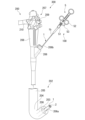
- FIG. 1 is an overall view of an endoscopic treatment system according to a first embodiment.
- 2 is an overall view showing a treatment tool of the endoscope treatment system.
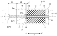
- FIG. FIG. 4 is a cross-sectional view of the distal end of the treatment tool.
- FIG. 4 is a cross-sectional view of the distal end of the treatment tool.
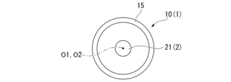
- FIG. 13 is a front view of a modified example of the flange of the treatment tool.
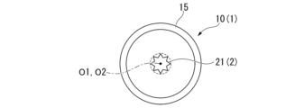
- FIG. 13 is a front view of a modified example of the flange of the treatment tool.
- FIG. 13A to 13C are diagrams showing a hemostasis step using the treatment tool.
- 13A and 13B are diagrams showing modified examples of the hard portion of the treatment tool.
- FIG. 13A and 13B are diagrams showing modified examples of the distal end tubular portion of the treatment tool.
- 13A and 13B are diagrams showing other modified examples of the tip tubular portion.
- 13A and 13B are diagrams showing other modified examples of the tip tubular portion.
- 13A and 13B are diagrams showing other modified examples of the tip tubular portion.
- FIG. 13 is a cross-sectional view of a distal end portion of a treatment tool according to a second embodiment.
- FIG. 13A and 13B are diagrams showing modified examples of the rod of the treatment tool.
- 13A and 13B are diagrams showing another modified example of the rod of the treatment tool.
- 13A and 13B are diagrams showing another modified example of the rod of the treatment tool.
- FIG. 13 is a cross-sectional view of the distal end of a treatment tool according to a third embodiment. 4 is a cross-sectional view of the distal end of the treatment tool.
- FIG. FIG. 13 is a perspective view showing a modified example of the cap of the treatment tool.
- FIG. 13 is a perspective view showing another modified example of the cap of the treatment tool.
- FIG. 13 is a perspective view showing a treatment tool according to a fourth embodiment.
- FIG. 1 is an overall view of the endoscopic treatment system 300 according to this embodiment.
- the endoscopic treatment system 300 includes an endoscope 200 and a treatment tool 100.
- the treatment tool 100 is inserted into the endoscope 200 when in use.
- the endoscope 200 is a known flexible endoscope, and includes an insertion section 202 that is inserted into the body from its tip, and an operation section 207 attached to the base end of the insertion section 202 .
- the insertion section 202 has an imaging section 203, a bending section 204, and a flexible section 205. From the tip of the insertion section 202, the imaging section 203, the bending section 204, and the flexible section 205 are arranged in this order. Inside the insertion section 202, a channel 206 for inserting the treatment tool 100 is provided inside the insertion section 202. A tip opening 206a of the channel 206 is provided at the tip of the insertion section 202.
- the imaging unit 203 is equipped with an imaging element such as a CCD or CMOS, and is capable of capturing an image of the area to be treated.
- the imaging unit 203 can capture an image of the rod 2 of the treatment tool 100 when the treatment tool 100 protrudes from the tip opening 206a of the channel 206.
- the bending section 204 bends in response to the operation of the operating section 207 by the operator.
- the flexible section 205 is a flexible tubular section.
- the operation unit 207 is connected to the flexible section 205.
- the operation unit 207 has a grip 208, an input unit 209, a base end opening 206b of the channel 206, and a universal cord 210.
- the grip 208 is a part that is held by an operator.
- the input unit 209 accepts operation input for bending the bending section 204.
- the universal cord 210 outputs the image captured by the imaging unit 203 to the outside.
- the universal cord 210 is connected to a display device such as a liquid crystal display via an image processing device equipped with a processor or the like.
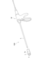
- FIG. 2 is an overall view showing the treatment tool 100.
- the treatment tool (endoscopic treatment tool) 100 is an ESD knife capable of performing incision and coagulation hemostasis.
- the treatment tool 100 includes a sheath 1, a rod 2, an operating wire 4 (see FIG. 3 ), and an operating section 5.
- the side that is inserted into the patient's body is referred to as the "tip side (distal side) A1," and the side of the operating section 5 is referred to as the "base side (proximal side) A2.”
- the sheath 1 is a long tubular member extending from the tip 1a to the base end 1b.
- the sheath 1 has an outer diameter that allows it to be inserted into the channel 206 of the endoscope 200, and it can advance and retract through the channel 206. As shown in FIG. 1, when the sheath 1 is inserted into the channel 206, the tip 1a of the sheath 1 can protrude and retract from the tip opening 206a of the channel 206.
- FIG. 3 is a perspective view of the distal end of the treatment tool 100.
- the sheath 1 has a tube 11 extending in a longitudinal direction A, and a rigid portion 12 attached to a distal end portion 10 of the sheath 1 .
- FIG. 4 and 5 are cross-sectional views of the distal end portion 10 of the treatment tool 100.
- FIG. The tube 11 is a long, flexible, and insulating tubular member made of, for example, resin.
- the rigid portion (tip) 12 is provided so as to close the internal space 19 of the tube 11.
- the rigid portion 12 has a through hole 13 that penetrates in the longitudinal direction A.
- the rod body 20 of the rod 2 is inserted into the through hole 13.
- the through hole 13 of the tip 12 is in communication with the internal space (duct, lumen) 19 of the tube 11.
- the hard portion 12 is attached to the distal end 10 of the sheath 1 on the base end side A2 relative to the distal end 1a of the sheath 1. Therefore, the distal end of the tube 11 is located on the distal end side A1 relative to the hard portion 12 at the distal end 10 of the sheath 1.
- the distal end of the tube 11 located on the distal end side A1 relative to the hard portion 12 at the distal end 10 of the sheath 1 is called the "tip tubular portion 15".
- the tip tubular portion 15 is a part of the tube 11.
- the tip tubular portion 15 is formed by including at least one of ceramic, zirconia, PTFE, and PEEK, for example.
- the tip tube portion 15 has a degree of transparency that allows the rod 2 to be seen from outside the sheath 1. More preferably, the tip tube portion 15 is made of a transparent material such as PTFE. This makes it easy for the surgeon to confirm the position of the rod 2 from the image captured by the imaging unit 203 of the endoscope 200.
- the rod (electrode) 2 is a round bar-shaped metal member. Note that the round bar shape is not limited to a strict cylindrical shape, but may be roughly formed into a round bar shape, and design errors are allowed.
- the rod 2 is formed from a material such as stainless steel.
- the rod 2 is conductive, and high-frequency current is passed through it.
- the rod 2 has a rod body 20, a flange 21, and a large diameter portion 22.
- the rod 2 is inserted in the through hole 13 of the rigid portion 12 of the sheath 1 along the longitudinal direction A so as to be movable forward and backward.
- the rod 2 can be advanced and retreated from a first position P1, where the tip of the rod 2 is located on the distal side A1 of the rigid portion 12 within the sheath 1, to a second position P2, where the tip of the rod 2 is located on the distal side A1 of the tip 1a of the sheath 1.
- the central axis O2 of the rod 2 in the longitudinal direction A coincides with the central axis O1 of the sheath 1 in the longitudinal direction A.
- the central axis O2 does not need to coincide perfectly with the central axis O1, and errors due to the effects of assembly errors, etc. are allowed.
- the rod body (electrode body) 20 is a round bar-shaped metal member.
- the operating wire 4 is attached to the base end of the rod body 20.
- a high-frequency current is supplied to the rod body 20 from the operating wire 4 connected to the operating section 5.
- the rod body 20 and the flange 21 function as a monopolar electrode that outputs the high-frequency current to the biological tissue.
- FIG. 6 is a front view of the distal end portion of the treatment tool 100.
- the flange (expanded diameter portion) 21 is a plate-shaped conductive member provided at the tip of the rod main body 20. In a front view seen from a direction along the longitudinal direction A, the flange 21 is formed in a triangular shape. The length of the flange 21 in a radial direction R perpendicular to the longitudinal direction A is longer than the length of the rod main body 20 in the radial direction R. As shown in Fig. 4, the rod 2 is positioned at a first position P1 with the flange 21 in contact with the hard portion 12.
- a flat base end surface (back surface) 21b is formed on the base end side A2 of the flange 21. As shown in FIG. 4, when the rod 2 is located in the first position P1, the base end surface 21b of the flange 21 and the tip portion 14 of the hard portion 12 abut against each other.
- FIG. 7 and 8 are front views of modified examples of the flange 21.
- FIG. The flange 21 may be round or polygonal in front view from the direction along the longitudinal direction A. From the viewpoint of outputting high-frequency current to biological tissue, the flange 21 is preferably polygonal with many corners. Furthermore, from the viewpoint of efficiently generating sparks in an intended range, it is preferable that the distal end tubular portion 15 is arranged concentrically with the rod 2 in the front view along the longitudinal direction A, and that the distal end tubular portion 15 is arranged concentrically with a virtual circle connecting the vertices of the polygonal shape. In other words, it is preferable that a plurality of vertices on the outermost circumference of the flange 21 are located on a virtual circle concentric with the rod 2.
- the large diameter portion 22 is located on the base end side A2 from the hard portion 12.
- the large diameter portion 22 has a larger diameter dimension, which is the length in the radial direction R, than the rod main body 20. As shown in FIG. 5, the rod 2 is positioned at the second position P2 with the large diameter portion 22 in contact with the hard portion 12.
- the second distance L2 from the tip of the rod 2 located at the first position P1 to the tip 1a of the sheath 1 is longer than the first distance L1 from the tip of the rod 2 located at the first position P1 to the tip of the hard portion 12.
- the second distance L2 from the tip of the rod 2 located at the first position P1 to the tip 1a of the sheath 1 is approximately equal to the third distance L3 from the tip of the rod 2 located at the second position P2 to the tip 1a of the sheath 1.
- the relationship between the fourth distance L4, which is the inner diameter of the sheath 1 (distance in the radial direction R), and the second distance L2 is preferably 0 ⁇ L2/L4 ⁇ 2. It is more preferable that 0 ⁇ L2/L4 ⁇ 1.
- the operating wire 4 is a metal wire that passes through the internal space (duct, lumen) 19 of the tube 11.
- the operating wire 4 is made of a material such as stainless steel.
- the tip of the operating wire 4 is connected to the rod 2, and the base end of the operating wire 4 is connected to the operating unit 5.
- the operation unit 5 has an operation unit main body 51, a slider 52, and a power supply connector 53.
- the tip of the operating unit body 51 is connected to the base end 1b of the sheath 1.
- the operating unit body 51 has an internal space through which the operating wire 4 can be inserted.
- the operating wire 4 passes through the internal space 19 of the tube 11 and the internal space of the operating unit body 51 and extends to the slider 52.
- the slider 52 is attached to the operation unit body 51 so as to be movable along the longitudinal direction A.
- the base end of the operation wire 4 is attached to the slider 52.
- the power supply connector 53 is fixed to the slider 52.
- the power supply connector 53 can be connected to a high-frequency power supply device (not shown) and is connected to the base end of the operation wire 4 via a conductive wire.
- the power supply connector 53 can supply high-frequency current supplied from the high-frequency power supply device to the rod 2 via the operation wire 4. Note that the power supply connector 53 may be fixed to the operation unit main body 51 instead of the slider 52.
- Method of using the endoscopic treatment system 300 Next, a procedure (method of using the endoscopic treatment system 300) using the endoscopic treatment system 300 of this embodiment will be described. Specifically, a local injection treatment, an incision and dissection treatment, and a hemostatic treatment of a lesion in an endoscopic treatment such as ESD (endoscopic submucosal dissection) will be described.
- ESD endoscopic submucosal dissection
- the surgeon identifies the affected area using a known method. Specifically, the surgeon inserts the insertion section 202 of the endoscope 200 into the digestive tract (e.g., esophagus, stomach, duodenum, large intestine) and identifies the affected area while observing the image obtained by the imaging section 203 of the endoscope.
- the digestive tract e.g., esophagus, stomach, duodenum, large intestine
- ⁇ Insertion step> The surgeon inserts the treatment tool 100 into the channel 206, and causes the tip 1a of the sheath 1 to protrude from the tip opening 206a of the insertion portion 202. The surgeon advances the slider 52 of the operation portion 5 relatively to the operation portion body 51, and causes the rod 2 to protrude.
- ⁇ Incision and peeling step> the surgeon performs an incision and dissection procedure.
- the surgeon advances the rod 2 to the second position P2, and while high-frequency current is being applied, moves the flange 21 to incise the mucosa of the lesion.
- the surgeon also advances the rod 2 to the second position P2, and while high-frequency current is being applied, lifts the mucosa of the incised lesion to expose the submucosa, and dissects the submucosa of the incised lesion.
- FIG. 9 is a diagram showing a hemostasis step using the treatment tool 100.
- the surgeon performs hemostasis procedures.
- the surgeon retracts the rod 2 to the first position P1.
- the surgeon presses the tip 1a of the sheath 1 against the biological tissue, bringing the tip 1a of the sheath 1 into close contact with the biological tissue.
- the surgeon surrounds the bleeding site H of the biological tissue with the distal tubular portion 15. The surgeon can easily maintain a non-contact state in which the tip (flange 21) of the rod 2 is an appropriate distance away from the bleeding site H of the biological tissue.
- the rod 2 comes into contact with the bleeding site H of the biological tissue, it will cause an increase in impedance of the biological tissue, carbonization, evaporation, etc., and a sufficient hemostatic effect will not be obtained. On the other hand, if the rod 2 is too far away from the bleeding site H of the biological tissue, it will not be possible to discharge to the bleeding site H.
- the surgeon can thermally deform the bleeding site H of the biological tissue and appropriately stop the bleeding by discharging the tip (flange 21) of the rod 2 in a non-contact state at an appropriate distance from the bleeding site H of the biological tissue.
- the bleeding site H and the flange 21 are an appropriate distance apart, the bleeding site H is located in the discharge space S surrounded by the tip tubular portion 15. Therefore, the discharge is not directed outside the sheath 1, and the discharge can be performed within the intended range of the bleeding site H. As a result, the bleeding site H is thermally deformed into a circular shape.
- the treatment tool 100 makes it easy to maintain a non-contact state in which the tip (flange 21) of the rod 2 is an appropriate distance away from the bleeding site H of the biological tissue.
- the bleeding site H is surrounded by the tip tubular portion 15. Therefore, the treatment tool 100 can discharge electricity to the intended range of the bleeding site H.
- the surgeon can easily perform an incision procedure or a dissection procedure by placing the rod 2 at the second position P2, and can easily perform a hemostasis procedure by discharging the bleeding site H by placing the rod 2 at the first position P1.
- FIG. 10 is a diagram showing a hard portion 12A which is a modified example of the hard portion 12. As shown in FIG. The hard portion 12A has a recess 16 capable of accommodating the flange 21 of the rod 2 on the tip side A1 of the through hole 13. The surgeon may discharge the electric current to the bleeding site H with the flange 21 accommodated in the recess 16.
- FIG. 11 is a diagram showing a tip tubular portion 15A which is a modified example of the tip tubular portion 15.
- the inner diameter (opening diameter) of the opening 15a at the tip of the tip tubular portion 15A is smaller than the outer diameter of the hard portion 12.
- the tip tubular portion 15A has a tapered inner circumferential surface so that the inner diameter becomes smaller toward the tip of the tip tubular portion 15A.
- the discharge space S that the tip tubular portion 15A surrounds the bleeding site H becomes smaller.
- the tip tubular portion 15B is a separate member from the tube 11, and is made of a material with superior heat resistance compared to the tube 11.
- the tip tubular portion 15B does not necessarily have to be a separate member as long as it is a material with high heat resistance.
- the tip tubular portion 15B is made of at least one of ceramic, zirconia, PTFE, and PEEK, for example.
- the tip tubular portion 15B and the tube 11 may be joined on the outer circumferential surface of the hard portion 12.
- the tip tubular portion 15B and the tube 11 are joined by adhesive or the like on the outer circumferential surface of the hard portion 12, so that the two are joined more firmly.
- Figures 14 and 15 show a tip tube portion 15C, which is a modified example of the tip tube portion 15.
- the tip tube portion 15C has a stretchable portion 17.
- the stretchable portion 17 shown in Figure 14 is formed in a bellows shape. As shown in Figure 15, even if the tip portion 10 of the sheath 1 cannot be pressed against the bleeding site H of the biological tissue from the front, the tip tube portion 15C can bring the entire circumference of the tip 1a of the sheath 1 into contact with the biological tissue by stretching the stretchable portion 17. As a result, the degree of sealing of the discharge space S can be increased.
- FIG. 16 A treatment tool 100B according to a second embodiment of the present invention will be described with reference to Fig. 16 to Fig. 19.
- components common to those already described will be denoted by the same reference numerals, and duplicated description will be omitted.
- FIG. 16 is a cross-sectional view of the distal end of the treatment tool 100B.
- the treatment tool (treatment tool for endoscope) 100B is a dedicated hemostatic instrument capable of performing coagulation hemostasis.
- the treatment tool 100B includes a sheath 1, a rod 2B, an operating wire 4, and an operating section 5.
- the treatment tool 100B differs from the treatment tool 100 of the first embodiment in that the rod 2B does not advance or retreat.
- the treatment tool 100B is used by being inserted into a channel 206 of an endoscope 200, similar to the treatment tool 100 of the first embodiment.
- the rod 2B is inserted into the through hole 13 formed in the hard portion 12 so that it cannot move forward or backward.
- the tip of the rod 2B is positioned at a first position P1 in the sheath 1, which is located on the distal side A1 of the hard portion 12. That is, the tip of the rod 2B is positioned between the tip of the tip tubular portion 15 and the hard portion 12.
- the rod 2B is fixed at the first position P1 by sandwiching the hard portion 12 between the flange (expanded portion) 21 and the large diameter portion 22, and the tip of the rod 2B, i.e., the flange (expanded portion) 21, is configured not to protrude from the tip of the sheath 1.
- “cannot move forward or backward” means that the function does not require movement forward or backward, and the rattle caused by errors or clearances that may occur in design or manufacturing are included in the "cannot move forward or backward” aspects.
- the second distance L2 from the tip of the rod 2B to the tip 1a of the sheath 1 is longer than the first distance L1 from the tip of the rod 2B to the tip of the hard portion 12.
- the relationship between the fourth distance L4, which is the inner diameter of the sheath 1 (distance in the radial direction R), and the second distance L2 is preferably 0 ⁇ L2/L4 ⁇ 2. It is more preferable that 0 ⁇ L2/L4 ⁇ 1.
- the surgeon can stop the bleeding site H using the treatment tool 100B in the same way as with the treatment tool 100 of the first embodiment.
- the treatment tool 100B makes it easy to maintain a non-contact state in which the tip (flange 21) of the rod 2B is an appropriate distance away from the bleeding site H of the biological tissue.
- the bleeding site H is surrounded by the tip tubular portion 15. Therefore, the treatment tool 100B can discharge electricity to the intended range of the bleeding site H.
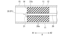
- 17 and 18 are diagrams showing a rod 2C which is a modified example of the rod 2B.
- the rod 2C does not have a large diameter portion 22.
- the rod 2C is fixed at the first position P1 by having a tip portion fixed to the hard portion 12.
- the base end surface 21b of the flange 21 may be disposed in contact with the tip portion 14 of the hard portion 12, or may be disposed slightly spaced apart from the tip portion 14 of the hard portion 12.
- the rod 2C may be fixed to the hard portion 12 by hooking a plurality of protrusions (concave and convex) 20a provided around the periphery of the rod main body 20 onto the hard portion 12.
- FIG. 19 is a diagram showing a rod 2D which is a modified example of the rod 2B.
- the rod 2D is positioned at the first position P1 by being biased toward the base end side A2 by an elastic member 23 such as a spring.
- the distal end tubular portion 15 of the treatment tool 100B may be tapered such that the inner diameter of the inner circumferential surface decreases toward the tip, as in the distal end tubular portion 15A shown in FIG. 11.
- the distal end tubular portion 15 of the treatment tool 100B may be a separate member from the tube 11, as in the distal end tubular portion 15B shown in FIGS. 12 and 13, and may be made of a material that is more heat resistant than the tube 11.
- a treatment tool 100C according to a third embodiment of the present invention will be described with reference to Fig. 20 to Fig. 23.
- the same components as those already described will be denoted by the same reference numerals, and duplicated description will be omitted.
- FIG. 20 is a perspective view of the distal end portion of the treatment tool 100C.
- the treatment tool (treatment tool for endoscope) 100C is an ESD knife capable of performing incision and coagulation hemostasis, to which a cap (outer tube) 3 is attached.
- the treatment tool 100C includes a sheath 1C, a rod 2, an operation wire 4, and an operation section 5.
- the treatment tool 100C is used by being inserted into a channel 206 of an endoscope 200, similar to the treatment tool 100 of the first embodiment.
- the sheath 1C is a long tubular member extending from the tip 1a to the base end 1b.
- the sheath 1 has a tube 11C extending in the longitudinal direction A and a hard portion 12 attached to the tip portion 10 of the sheath 1.
- the tube 11C differs from the tube 11 of the first embodiment in that it does not have a tip tubular portion 15 extending to the tip side A1 of the hard portion 12.
- FIG. 21 is a cross-sectional view of the distal end portion of the treatment tool 100C.
- the cap (outer tube) 3 is an insulating tubular member that can be attached to and detached from the tip of the sheath 1.
- the cap 3 has a step 31 on its inner circumferential surface. When the cap 3 is attached to the outer circumferential surface of the tip of the sheath 1, the step 31 abuts against the tip 1a of the sheath 1, and the cap 3 is positioned relative to the sheath 1.
- the step 31 is a protrusion that protrudes inward in the radial direction R from the inner circumferential surface.
- the rod 2 is inserted in the through hole 13 of the hard portion 12 of the sheath 1 along the longitudinal direction A so as to be movable forward and backward.
- the rod 2 can be advanced and retreated from a first position P1, where the tip of the rod 2 is located on the distal side A1 of the hard portion 12 within the cap 3, to a second position P2, where the tip of the rod 2 is located on the distal side A1 of the tip 3a of the cap 3.
- the central axis O2 of the rod 2 in the longitudinal direction A is approximately aligned with the central axis O3 of the cap 3 in the longitudinal direction A.
- the rod 2 is positioned at the first position P1 with the flange 21 in contact with the hard portion 12.
- the tip of the cap 3 is located on the distal side A1 of the tip of the rod 2.
- the second distance L2 from the tip of the rod 2 located at the first position P1 to the tip 3a of the cap 3 is longer than the first distance L1 from the tip of the rod 2 located at the first position P1 to the tip of the hard portion 12.
- the relationship between the fourth distance L4, which is the inner diameter of the cap (distance in the radial direction R), and the second distance L2 is preferably 0 ⁇ L2/L4 ⁇ 2. It is more preferable that 0 ⁇ L2/L4 ⁇ 1.
- the tip of the cap 3 located on the tip side A1 from the step 31 is called the "tip tubular portion 35."
- the tip tubular portion 35 can surround the bleeding site H, similar to the tip tubular portion 15 of the first embodiment.
- the distal end tube portion 35 is preferably transparent enough to allow the rod 2 to be seen from outside the cap 3. The surgeon can easily confirm the position of the rod 2 from the image captured by the imaging unit 203 of the endoscope 200.
- the tip tube portion 35 is desirably made of a material with excellent heat resistance.
- the cap 3 is desirably made of at least one of the following materials: ceramic, zirconia, PTFE, and PEEK.
- the tip tubular portion 35 may have an inner diameter (opening diameter) of the opening 35a at the tip that is smaller than the outer diameter of the hard portion 12, similar to the tip tubular portion 15A shown in FIG. 11.
- the tip tubular portion 35 may also have a tapered inner circumferential surface such that the inner diameter becomes smaller toward the tip of the tip tubular portion 35.
- the treatment tool 100C makes it easy to maintain a non-contact state in which the tip (flange 21) of the rod 2 is an appropriate distance away from the bleeding site H of the biological tissue.
- the bleeding site H is surrounded by the tip tubular portion 35. Therefore, the treatment tool 100C can discharge electricity to the intended range of the bleeding site H.
- FIG. 22 is a perspective view showing a cap 3A which is a modified example of the cap 3.
- the cap 3A has a marking 32 instead of the step 31.
- the marking 32 is formed along the circumferential direction on the inner peripheral surface of the cap.
- FIG. 23 is a perspective view showing a cap 3B which is a modified example of the cap 3. As shown in FIG. The cap 3B does not have a step 31.
- the cap 3B has a distal end hard portion 33 provided on the distal end side A1 and a proximal end soft portion 34 provided on the proximal end side A2.
- the proximal end soft portion 34 is softer than the distal end hard portion 33 and is easy to attach to the distal end of the sheath 1.
- the surgeon attaches only the proximal end soft portion 34 to the distal end 1a of the sheath 1. This positions the cap 3B relative to the sheath 1.
- FIG. 24 A treatment tool 100D according to a fourth embodiment of the present invention will be described with reference to Fig. 24.
- configurations common to those already described will be given the same reference numerals and duplicated description will be omitted.
- FIG. 24 is a perspective view showing the treatment tool 100D.
- the treatment tool (endoscopic treatment tool) 100D is a surgical treatment tool for water supply, suction, hemostasis, etc., and can perform incision and coagulation hemostasis.
- the treatment tool 100D includes a shaft 6, a rod 2, a cap (outer tube) 3, and an operation section 5D.
- the shaft 6 is a rod-shaped member made of, for example, metal.
- the rod 2 is inserted into the shaft 6.
- the rod 2 can be extended and retracted from the tip 6a of the shaft 6.
- the cap (outer tube) 3 is a tubular member that can be attached and detached to the tip 6a of the shaft 6, and has insulating properties.
- the cap 3 is positioned relative to the shaft 6 in the same manner as in the third embodiment.
- the surgeon can stop the bleeding site H using the treatment tool 100D in the same way as the treatment tool 100C of the third embodiment.
- the treatment tool 100D makes it easy to maintain a non-contact state in which the tip (flange 21) of the rod 2 is an appropriate distance away from the bleeding site H of the biological tissue.
- the bleeding site H is surrounded by the tip tubular portion 35. Therefore, the treatment tool 100D can discharge electricity to the intended range of the bleeding site H.
- the present invention can be applied to endoscopic treatment tools used for hemostasis treatment.
- Endoscope treatment system 200 Endoscope 100, 100B, 100C, 100D Treatment tool (endoscopic treatment tool) 1, 1C Sheath 1a Distal end 1b Base end 10 Distal end portion 11, 11C Tube 12, 12A Hard portion (distal tip) 13 Through hole 14 Tip portion 15, 15A, 15B, 15C Tip tubular portion 15a Opening 16 Recess 17 Expandable portion 19 Internal space (duct, lumen) 2, 2B, 2C, 2D Rod (electrode) 20 Rod body (electrode body) 21 Flange (expanded diameter portion) 21b Base end surface (back surface) 22 Large diameter portion 23 Elastic member 3, 3A, 3B Cap (outer tube) 3a Distal end 31 Step 32 Marking 33 Distal end hard portion 34 Base end soft portion 35 Distal end tubular portion 35a Opening 4 Operation wire 5, 5D Operation portion 51 Operation portion main body 52 Slider 53 Power supply connector 6 Shaft 6a Distal end
Landscapes
- Health & Medical Sciences (AREA)
- Life Sciences & Earth Sciences (AREA)
- Surgery (AREA)
- Engineering & Computer Science (AREA)
- General Health & Medical Sciences (AREA)
- Veterinary Medicine (AREA)
- Public Health (AREA)
- Physics & Mathematics (AREA)
- Nuclear Medicine, Radiotherapy & Molecular Imaging (AREA)
- Animal Behavior & Ethology (AREA)
- Biomedical Technology (AREA)
- Heart & Thoracic Surgery (AREA)
- Medical Informatics (AREA)
- Molecular Biology (AREA)
- Plasma & Fusion (AREA)
- Otolaryngology (AREA)
- Biophysics (AREA)
- Radiology & Medical Imaging (AREA)
- Pathology (AREA)
- Optics & Photonics (AREA)
- Cardiology (AREA)
- Surgical Instruments (AREA)
Priority Applications (4)
| Application Number | Priority Date | Filing Date | Title |
|---|---|---|---|
| CN202480023307.5A CN121013677A (zh) | 2023-03-29 | 2024-01-16 | 内窥镜用处置器具 |
| DE112024001086.5T DE112024001086T5 (de) | 2023-03-29 | 2024-01-16 | Behandlungswerkzeug für ein Endoskop |
| JP2025509776A JPWO2024202400A1 (https=) | 2023-03-29 | 2024-01-16 | |
| US19/340,230 US20260020901A1 (en) | 2023-03-29 | 2025-09-25 | Treatment tool for endoscope |
Applications Claiming Priority (2)
| Application Number | Priority Date | Filing Date | Title |
|---|---|---|---|
| US202363492883P | 2023-03-29 | 2023-03-29 | |
| US63/492,883 | 2023-03-29 |
Related Child Applications (1)
| Application Number | Title | Priority Date | Filing Date |
|---|---|---|---|
| US19/340,230 Continuation US20260020901A1 (en) | 2023-03-29 | 2025-09-25 | Treatment tool for endoscope |
Publications (1)
| Publication Number | Publication Date |
|---|---|
| WO2024202400A1 true WO2024202400A1 (ja) | 2024-10-03 |
Family
ID=92904838
Family Applications (1)
| Application Number | Title | Priority Date | Filing Date |
|---|---|---|---|
| PCT/JP2024/000935 Ceased WO2024202400A1 (ja) | 2023-03-29 | 2024-01-16 | 内視鏡用処置具 |
Country Status (5)
| Country | Link |
|---|---|
| US (1) | US20260020901A1 (https=) |
| JP (1) | JPWO2024202400A1 (https=) |
| CN (1) | CN121013677A (https=) |
| DE (1) | DE112024001086T5 (https=) |
| WO (1) | WO2024202400A1 (https=) |
Citations (5)
| Publication number | Priority date | Publication date | Assignee | Title |
|---|---|---|---|---|
| JP2008529610A (ja) * | 2005-02-11 | 2008-08-07 | デール ヴィクター マッカイ、 | 電気手術用プロープ |
| JP2010042155A (ja) * | 2008-08-13 | 2010-02-25 | Olympus Medical Systems Corp | 内視鏡用処置具 |
| JP2013504346A (ja) * | 2009-09-11 | 2013-02-07 | エルベ エレクトロメディジン ゲーエムベーハー | 多機能部材、および多機能部材によって組織の炭化を防止する方法 |
| WO2016021230A1 (ja) * | 2014-08-06 | 2016-02-11 | オリンパス株式会社 | 高周波処置具 |
| JP2022531008A (ja) * | 2019-05-06 | 2022-07-05 | ボストン サイエンティフィック サイムド,インコーポレイテッド | 医療装置 |
-
2024
- 2024-01-16 CN CN202480023307.5A patent/CN121013677A/zh active Pending
- 2024-01-16 WO PCT/JP2024/000935 patent/WO2024202400A1/ja not_active Ceased
- 2024-01-16 JP JP2025509776A patent/JPWO2024202400A1/ja active Pending
- 2024-01-16 DE DE112024001086.5T patent/DE112024001086T5/de active Pending
-
2025
- 2025-09-25 US US19/340,230 patent/US20260020901A1/en active Pending
Patent Citations (5)
| Publication number | Priority date | Publication date | Assignee | Title |
|---|---|---|---|---|
| JP2008529610A (ja) * | 2005-02-11 | 2008-08-07 | デール ヴィクター マッカイ、 | 電気手術用プロープ |
| JP2010042155A (ja) * | 2008-08-13 | 2010-02-25 | Olympus Medical Systems Corp | 内視鏡用処置具 |
| JP2013504346A (ja) * | 2009-09-11 | 2013-02-07 | エルベ エレクトロメディジン ゲーエムベーハー | 多機能部材、および多機能部材によって組織の炭化を防止する方法 |
| WO2016021230A1 (ja) * | 2014-08-06 | 2016-02-11 | オリンパス株式会社 | 高周波処置具 |
| JP2022531008A (ja) * | 2019-05-06 | 2022-07-05 | ボストン サイエンティフィック サイムド,インコーポレイテッド | 医療装置 |
Also Published As
| Publication number | Publication date |
|---|---|
| CN121013677A (zh) | 2025-11-25 |
| US20260020901A1 (en) | 2026-01-22 |
| JPWO2024202400A1 (https=) | 2024-10-03 |
| DE112024001086T5 (de) | 2025-12-18 |
Similar Documents
| Publication | Publication Date | Title |
|---|---|---|
| JP4870710B2 (ja) | 高周波ナイフおよび高周波ナイフシステム | |
| CN110693604B (zh) | 内窥镜及扩展支架 | |
| KR20050033471A (ko) | 고주파 나이프 및 내시경 장치 | |
| US12310866B2 (en) | Methods and devices for performing electrosurgery | |
| WO2016006407A1 (ja) | 内視鏡的粘膜下層剥離術用デバイス及び内視鏡システム | |
| JP7467707B2 (ja) | 内視鏡用処置具 | |
| CN107072491B (zh) | 插入设备的插入部安装器具、插入系统 | |
| CN116390695A (zh) | 具有电极环的ent消融器械 | |
| KR20070097497A (ko) | 절제기능을 갖는 후드 및 내시경 | |
| JP7600273B2 (ja) | 内視鏡用処置具 | |
| WO2020213025A1 (ja) | 内視鏡用スネア | |
| JP7592756B2 (ja) | 処置具 | |
| WO2024202400A1 (ja) | 内視鏡用処置具 | |
| US20230136593A1 (en) | Treatment tool for endoscope | |
| JP7712348B2 (ja) | 内視鏡用処置具および内視鏡用処置具システム | |
| JP7459311B2 (ja) | 処置具 | |
| US20250228601A1 (en) | Endoscope treatment tool and treatment method | |
| KR101750654B1 (ko) | 내시경 점막하 박리술에 이용되는 나이프 | |
| JP7659037B2 (ja) | 内視鏡用処置具 | |
| US20260114901A1 (en) | Endoscopic method | |
| US20260000442A1 (en) | Endoscopic treatment instrument | |
| CN116531080A (zh) | 内窥镜用处置器具 | |
| WO2025192153A1 (ja) | 内視鏡用処置具 | |
| WO2022230930A1 (ja) | 内視鏡用針状メス |
Legal Events
| Date | Code | Title | Description |
|---|---|---|---|
| 121 | Ep: the epo has been informed by wipo that ep was designated in this application |
Ref document number: 24778546 Country of ref document: EP Kind code of ref document: A1 |
|
| ENP | Entry into the national phase |
Ref document number: 2025509776 Country of ref document: JP Kind code of ref document: A |
|
| WWE | Wipo information: entry into national phase |
Ref document number: 2025509776 Country of ref document: JP |
|
| WWE | Wipo information: entry into national phase |
Ref document number: 112024001086 Country of ref document: DE |
|
| WWP | Wipo information: published in national office |
Ref document number: 112024001086 Country of ref document: DE |
|
| 122 | Ep: pct application non-entry in european phase |
Ref document number: 24778546 Country of ref document: EP Kind code of ref document: A1 |