WO2024202377A1 - 切削インサート、切削工具及び切削加工物の製造方法 - Google Patents
切削インサート、切削工具及び切削加工物の製造方法 Download PDFInfo
- Publication number
- WO2024202377A1 WO2024202377A1 PCT/JP2024/000094 JP2024000094W WO2024202377A1 WO 2024202377 A1 WO2024202377 A1 WO 2024202377A1 JP 2024000094 W JP2024000094 W JP 2024000094W WO 2024202377 A1 WO2024202377 A1 WO 2024202377A1
- Authority
- WO
- WIPO (PCT)
- Prior art keywords
- recess
- corner
- width
- cutting insert
- cutting
- Prior art date
- Legal status (The legal status is an assumption and is not a legal conclusion. Google has not performed a legal analysis and makes no representation as to the accuracy of the status listed.)
- Ceased
Links
Images








Classifications
-
- B—PERFORMING OPERATIONS; TRANSPORTING
- B23—MACHINE TOOLS; METAL-WORKING NOT OTHERWISE PROVIDED FOR
- B23C—MILLING
- B23C5/00—Milling-cutters
- B23C5/16—Milling-cutters characterised by physical features other than shape
- B23C5/20—Milling-cutters characterised by physical features other than shape with removable cutter bits or teeth or cutting inserts
- B23C5/202—Plate-like cutting inserts with special form
-
- B—PERFORMING OPERATIONS; TRANSPORTING
- B23—MACHINE TOOLS; METAL-WORKING NOT OTHERWISE PROVIDED FOR
- B23B—TURNING; BORING
- B23B27/00—Tools for turning or boring machines; Tools of a similar kind in general; Accessories therefor
- B23B27/14—Cutting tools of which the bits or tips or cutting inserts are of special material
- B23B27/141—Specially shaped plate-like cutting inserts, i.e. length greater or equal to width, width greater than or equal to thickness
-
- B—PERFORMING OPERATIONS; TRANSPORTING
- B23—MACHINE TOOLS; METAL-WORKING NOT OTHERWISE PROVIDED FOR
- B23C—MILLING
- B23C5/00—Milling-cutters
- B23C5/02—Milling-cutters characterised by the shape of the cutter
- B23C5/06—Face-milling cutters, i.e. having only or primarily a substantially flat cutting surface
-
- B—PERFORMING OPERATIONS; TRANSPORTING
- B23—MACHINE TOOLS; METAL-WORKING NOT OTHERWISE PROVIDED FOR
- B23C—MILLING
- B23C5/00—Milling-cutters
- B23C5/02—Milling-cutters characterised by the shape of the cutter
- B23C5/10—Shank-type cutters, i.e. with an integral shaft
-
- B—PERFORMING OPERATIONS; TRANSPORTING
- B23—MACHINE TOOLS; METAL-WORKING NOT OTHERWISE PROVIDED FOR
- B23C—MILLING
- B23C5/00—Milling-cutters
- B23C5/16—Milling-cutters characterised by physical features other than shape
- B23C5/20—Milling-cutters characterised by physical features other than shape with removable cutter bits or teeth or cutting inserts
-
- B—PERFORMING OPERATIONS; TRANSPORTING
- B23—MACHINE TOOLS; METAL-WORKING NOT OTHERWISE PROVIDED FOR
- B23B—TURNING; BORING
- B23B2200/00—Details of cutting inserts
- B23B2200/04—Overall shape
- B23B2200/0438—Octagonal
- B23B2200/0442—Octagonal rounded
-
- B—PERFORMING OPERATIONS; TRANSPORTING
- B23—MACHINE TOOLS; METAL-WORKING NOT OTHERWISE PROVIDED FOR
- B23B—TURNING; BORING
- B23B2200/00—Details of cutting inserts
- B23B2200/12—Side or flank surfaces
- B23B2200/128—Side or flank surfaces with one or more grooves
-
- B—PERFORMING OPERATIONS; TRANSPORTING
- B23—MACHINE TOOLS; METAL-WORKING NOT OTHERWISE PROVIDED FOR
- B23B—TURNING; BORING
- B23B2205/00—Fixation of cutting inserts in holders
- B23B2205/21—Systems for changing the cutting insert automatically
-
- B—PERFORMING OPERATIONS; TRANSPORTING
- B23—MACHINE TOOLS; METAL-WORKING NOT OTHERWISE PROVIDED FOR
- B23C—MILLING
- B23C2200/00—Details of milling cutting inserts
- B23C2200/04—Overall shape
- B23C2200/0422—Octagonal
- B23C2200/0427—Octagonal rounded
-
- B—PERFORMING OPERATIONS; TRANSPORTING
- B23—MACHINE TOOLS; METAL-WORKING NOT OTHERWISE PROVIDED FOR
- B23C—MILLING
- B23C2200/00—Details of milling cutting inserts
- B23C2200/12—Side or flank surfaces
- B23C2200/128—Side or flank surfaces with one or more grooves
Definitions
- the present disclosure relates to a cutting insert, a cutting tool, and a method for manufacturing a machined product.
- cutting tools include rotary tools and turning tools.
- rotary tools include cutting tools (milling tools).
- Turning tools are used for turning processes such as face milling and end milling.
- turning tools include external diameter machining tools, internal diameter machining tools, grooving tools, and cut-off tools.
- the cutting inserts described in Patent Documents 1 to 3 are known as cutting inserts used in cutting tools.
- the cutting insert described in Patent Document 1 has a recess in the portion of the side along the corner of the top surface to make it easier to hold with a robot hand.
- the cutting insert described in Patent Document 2 has a recess in the portion of the side along the corner of the top surface to prevent cracks from progressing.
- the cutting insert described in Patent Document 3 has a groove in the portion of the side along the edge of the top surface to break up chips.
- the cutting insert according to the present disclosure has an upper surface, a lower surface opposite the upper surface, a side surface connected to the upper surface and the lower surface, and an upper cutting edge located at the intersection of the upper surface and the side surface
- the upper surface has a first side, a second side, and a first corner connected to the first side and the second side
- the side surface has a first side surface connected to the first side, a second side surface connected to the second side, and a first corner side surface connected to the first corner
- the first side surface has a first recess
- the The second side has a second recess, and in a direction parallel to the top surface, the distance from the first recess to the first corner side is a first distance, the distance from the second recess to the first corner side is a second distance, the width of the first recess is a first width, and the width of the second recess is a second width, the first width and the second width are smaller than the first distance and the second distance, and when the first corner side is
- the cutting tool according to the present disclosure includes a holder having a shape extending from a first end to a second end and a pocket located on the side of the first end, and a cutting insert according to the present disclosure located within the pocket.
- the method for manufacturing a machined product according to the present disclosure includes the steps of rotating a cutting tool according to the present disclosure, bringing the cutting tool into contact with a workpiece, and removing the cutting tool from the workpiece.
- the method for manufacturing a machined product according to the present disclosure includes the steps of rotating a workpiece, bringing a cutting tool according to the present disclosure into contact with the rotating workpiece, and removing the cutting tool from the workpiece.
- FIG. 2 is a schematic perspective view showing a cutting tool according to an embodiment of the present disclosure with only one cutting insert attached thereto;
- FIG. 2 is a schematic perspective view showing a state in which a cutting insert according to an embodiment of the present disclosure is attached to a holder.
- FIG. 3 is a schematic side view showing a state in which the cutting insert shown in FIG. 2 is attached to a holder.
- 4 is a cross-sectional view taken along line IV-IV of FIG. 3.
- 3 is a cross-sectional view showing the shape of a cross section passing through a first corner side surface and perpendicular to the top surface of the cutting insert shown in FIG. 2.
- FIG. 11 is a schematic perspective view showing a state in which a cutting insert according to another embodiment of the present disclosure is attached to a holder.
- FIG. 11 is a schematic perspective view showing a state in which a cutting insert according to yet another embodiment of the present disclosure is attached to a holder.
- FIG. 8 is a schematic side view showing a state in which the cutting insert shown in FIG. 7 is attached to a holder.
- 10 is a cross-sectional view taken along line XII-XII in FIG. 8 .
- FIG. 11 is a schematic perspective view showing a state in which a cutting insert according to yet another embodiment of the present disclosure is attached to a holder.
- FIG. 11 is a schematic side view showing a state in which the cutting insert shown in FIG.
- 1A to 1C are schematic diagrams illustrating a manufacturing method of a machined product according to an embodiment of the present disclosure.
- 1A to 1C are schematic diagrams illustrating a manufacturing method of a machined product according to an embodiment of the present disclosure.
- 1A to 1C are schematic diagrams illustrating a manufacturing method of a machined product according to an embodiment of the present disclosure.
- Cutting tools are used while attached to machine tools such as NC (Numerical Control) lathes or machining centers.
- machine tools such as NC (Numerical Control) lathes or machining centers.
- NC Genetic Control
- machining centers When replacing cutting inserts in such machine tools, the work space inside the machine tool is limited, which can make the work complicated.
- the limited work space mentioned above can be a major obstacle when automating the replacement of cutting inserts.
- a groove is provided on the side along the edge of the top surface.
- the cutting insert is easier to grasp with a robot hand compared to the cutting inserts described in Patent Documents 1 and 2.
- the groove in Patent Document 3 is intended to break up the chips, it is necessary to form the groove so that it extends long in the vertical and horizontal directions when viewed from the side, which may reduce the durability of the cutting insert.
- each of the drawings referred to below shows a simplified view of only the components necessary for explaining the embodiment. Therefore, the cutting tool according to the embodiment of the present disclosure may include any components not shown in each of the drawings referred to. Furthermore, the dimensions of the components in each drawing do not faithfully represent the actual dimensions of the components and the dimensional ratios of each member, etc.
- FIG. 1 is a schematic perspective view showing a state in which only one cutting insert 10 is attached to the cutting tool 1 according to the embodiment of the present disclosure.
- the cutting tool 1 according to the embodiment of the present disclosure is a tool used for cutting a workpiece W (see Fig. 13) and is rotatable around a rotation axis RS.
- the cutting tool 1 may have a holder 40 that is attached to the spindle of a processing machine such as a milling machine.
- the holder 40 may have a shape that extends from a first end (tip) 40a to a second end (rear end) 40b along the rotation axis RS.
- the holder 40 may have a cylindrical shape as shown in the example, or may have a rectangular column shape, etc. Examples of materials for the holder 40 include metals such as stainless steel, carbon steel, cast iron, and aluminum alloys.
- the holder 40 may have a pocket 42 located on the side of the first end 40a.
- the pocket 42 may be a recess for mounting the cutting insert 10.
- the pocket 42 may be located on the outer peripheral surface of the holder 40 in a plurality of locations.
- the multiple pockets 42 may be spaced apart in the circumferential direction on the outer circumferential surface of the holder 40. In this case, they may be spaced apart in the circumferential direction at equal intervals, or they may be spaced apart in the circumferential direction at unequal intervals. In addition, the number of pockets 42 for each holder 40 may be one.
- the cutting tool 1 may have a cutting insert 10 located in a pocket 42 of the holder 40.
- the cutting insert 10 may be located only in one or more selected pockets 42 in the holder 40.
- Fig. 2 is a schematic perspective view showing a state in which the cutting insert 10 according to the embodiment of the present disclosure is attached to a holder 40.
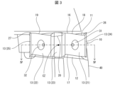
- Fig. 3 is a schematic side view showing a state in which the cutting insert 10 shown in Fig. 2 is attached to the holder 40.
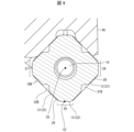
- Fig. 4 is a cross-sectional view taken along line IV-IV in Fig. 3.
- Fig. 5 is a cross-sectional view showing the shape of a cross section passing through the first corner side surface 23 and perpendicular to the upper surface 11 in the cutting insert 10 shown in Fig. 2.
- the cutting insert 10 is a component of a cutting tool used for cutting a workpiece W (see FIG. 13) made of a metal material or the like.
- Examples of cutting the workpiece W include shoulder milling, groove milling, R milling, and profiling.
- the cutting insert 10 may have an upper surface 11 and a lower surface 12 located opposite the upper surface 11.
- the upper surface 11 and the lower surface 12 may each be polygonal, for example, octagonal.
- the cutting insert 10 may be polygonal plate-shaped, for example, octagonal plate-shaped.
- the upper surface 11 and the lower surface 12 may each be polygonal other than an octagonal shape, such as a triangular or rectangular shape.
- the cutting insert 10 may be polygonal other than an octagonal plate shape, such as a triangular or rectangular plate shape.
- the polygonal shape is not limited to a polygonal shape in the strict sense.
- the upper surface 11 and the lower surface 12 may each have a rotationally symmetric shape at a fixed angle around the insert central axis CS.
- the upper surface 11 and the lower surface 12 may each have a shape that is inverted symmetric on the front and back.
- the cutting insert 10 may have a rotationally symmetric shape at a fixed angle around the insert central axis CS, or may each have a shape that is inverted symmetric on the front and back.
- the cutting insert 10 may have a side surface 13 located between the upper surface 11 and the lower surface 12.
- the side surface 13 may be connected to the upper surface 11 and the lower surface 12.
- the side surface 13 may function as a clearance surface and may be parallel to the insert central axis CS.
- the cutting insert 10 may have a mounting hole 14 that penetrates from the upper surface 11 to the lower surface 12.
- the central axis of the mounting hole 14 may coincide with the insert central axis CS.
- the cutting insert 10 may have an upper cutting edge 16 located at the intersection of the upper surface 11 and the side surface 13.
- the cutting insert 10 may also have a lower cutting edge 17 located at the intersection of the lower surface 12 and the side surface 13.
- the cutting insert 10 may be a double-sided insert with an upper cutting edge 16 and a lower cutting edge 17.
- the upper surface 11 may have a first side 18, a second side 19, and a first corner 20 connected to the first side 18 and the second side 19.
- the first side 18 may be linear in top view, and may approach the lower surface 12 as it moves away from the first corner 20 in side view.
- the second side 19 may be linear in top view, and may approach the lower surface 12 as it moves closer to the first corner 20 in side view.
- the side surface 13 may have a first side surface 21 connected to the first edge 18, a second side surface 22 connected to the second edge 19, and a first corner side surface 23 connected to the first corner 20.
- the first side surface 21 may have a first recess 31, and the second side surface 22 may have a second recess 32.
- the shape of the first recess 31 when the first side surface 21 is viewed from the front may be circular, elliptical, or polygonal.
- the shape of the second recess 32 when the second side surface 22 is viewed from the front may be circular, elliptical, or polygonal.
- the internal shapes of the first recess 31 and the second recess 32 may be cone-shaped, cone-shaped with a rounded apex, rectangular parallelepiped, etc.
- the first recess 31 is provided on the first side surface 21 and the second recess 32 is provided on the second side surface 22, so that when replacing the cutting insert 10, the claws of a robot hand in a device such as a robot arm used for replacement can be inserted into the first recess 31 and the second recess 32 to grip the cutting insert.
- the claws of a robot hand in a device such as a robot arm used for replacement
- the claws of a robot hand in a device such as a robot arm used for replacement
- the cutting insert 10 may be configured such that in a direction parallel to the upper surface 11, the distance from the first recess 31 to the first corner side surface 23 is a first distance D1, the distance from the second recess 32 to the first corner side surface 23 is a second distance D2, the width of the first recess 31 is a first width W1, and the width of the second recess 32 is a second width W2, and the first width W1 and the second width W2 are smaller than the first distance D1 and the second distance D2.
- the first distance D1 may be the shortest distance between the first recess 31 and the first corner side 23 in a direction parallel to the top surface 11.
- the second distance D2 may be the shortest distance between the second recess 32 and the first corner side 23 in a direction parallel to the top surface 11.
- the first recess 31 and the second recess 32 may be positioned rotationally symmetrical with respect to the center CZ of the first corner side 23 (indicated by a dot in the figure).
- the cutting insert 10 is an insert that can be used upside down, the positions of the first recess 31 and the second recess 32 do not change even if the cutting insert 10 is installed upside down. This simplifies the task of gripping the cutting insert 10 with a robot hand, and simplifies the movement of the device, making it possible to avoid complicating the device.
- the cutting insert 10 may have the first recess 31 and the second recess 32 provided at the same position in the vertical direction from the upper surface 11 to the lower surface 12.
- the positions of the first recess 31 and the second recess 32 do not change even if the cutting insert 10 is rotated at a fixed angle and attached. This simplifies the task of gripping the cutting insert 10 with a robot hand, and simplifies the movement of the device, thereby avoiding the device from becoming complicated.
- a first recess 31 and a second recess 32 are formed on adjacent sides of each side except the corner side.
- the first recess 31 has a first wall surface 31a located on the side of the second recess 32
- the second recess 32 has a second wall surface 32a located on the side of the first recess 31.
- an extension line L1 of the first wall surface 31a and an extension line L2 of the second wall surface 32a may be parallel to each other, or may have an inclination that intersects on the side where the center of the top surface 11 is located.
- the center of the top surface 11 may be the insert central axis CS.
- the claws of the robot hand are inserted into the first recess 31 and the second recess 32 from the front side of the first corner side 23, and the claws come into contact with the first wall surface 31a and the second wall surface 32a to grip the insert.
- the first wall surface 31a and the second wall surface 32a that the claws contact are parallel or have an inclination that approaches each other toward the side where the center of the upper surface 11 is located, so that the claws can easily grip the first wall surface 31a and the second wall surface 32a.
- the first corner side 23 may have a linear or convex shape. In other words, the first corner side 23 does not have a recess into which the claws of a robot hand can be inserted.
- This configuration reduces the risk of a decrease in the durability of the cutting insert 10.
- the top surface 11 may further have a second corner 26 connected to a side of the first edge 18 different from the first corner 20, and a third corner 27 connected to a side of the second edge 19 different from the first corner 20.
- the side surface 13 may further have a second corner side surface 24 connected to the second corner 26, and a third corner side surface 25 connected to the third corner 27.
- Cutting insert 10A 6 is a schematic perspective view showing a state in which a cutting insert 10A according to another embodiment of the present disclosure is attached to a holder 40.
- the same reference numerals are used for members having the same functions as those described in the above-mentioned embodiment, and the explanation in the above-mentioned embodiment is used.
- the cutting insert 10A may be configured such that, in the vertical direction from the upper surface 11 to the lower surface 12, the width from the first recess 31A to the upper surface 11 is a first height H1, the width from the first recess 31A to the lower surface 12 is a second height H2, and the width of the first recess 31A is a third height H3, with the third height H3 being smaller than the first height H1 and the second height H2.
- the cutting insert 10A By configuring the cutting insert 10A in this way, while providing the first recess 31A, the distance between the upper surface 11, where the upper cutting edge 16 is located at the intersection with the side surface 13, and the lower surface 12, where the lower cutting edge 17 is located, and the first recess 31A is ensured, thereby ensuring the strength of the upper cutting edge 16 and the lower cutting edge 17.
- the cutting insert 10A may be configured such that, in the vertical direction from the upper surface 11 to the lower surface 12, the width from the second recess 32A to the upper surface 11 is a first height H1', the width from the second recess 32A to the lower surface 12 is a second height H2', and the width of the second recess 32A is a third height H3', with the third height H3' being smaller than the first height H1' and the second height H2'.
- the distance between the upper surface 11 where the upper cutting edge 16 is located and the lower surface 12 where the lower cutting edge 17 is located at the intersection with the side surface 13 is secured, and the first recess 31A can be secured to ensure the strength of the upper cutting edge 16 and the lower cutting edge 17.
- Fig. 7 is a schematic perspective view showing a state in which a cutting insert 10B according to yet another embodiment of the present disclosure is attached to a holder 40.
- Fig. 8 is a schematic side view showing a state in which the cutting insert 10B shown in Fig. 7 is attached to a holder 40.
- Fig. 9 is a cross-sectional view taken along line IX-IX in Fig. 8.
- the cutting insert 10B may have a first groove portion 28 on the first side surface 21 that extends in a direction parallel to the top surface 11.
- the cutting insert 10B may also have a second groove portion 29 on the second side surface 22 that extends in a direction parallel to the top surface 11.
- the first groove portion 28 and the second groove portion 29 may be located in the center of the first side surface 21 and the second side surface 22 in the up-down direction.
- the first recess 31B may be located in the first groove portion 28, and the second recess 32B may be located in the second groove portion 29.
- the first recess 31B and the second recess 32B may be located in the center of the first groove portion 28 and the second groove portion 29, respectively, in a direction parallel to the upper surface 11.
- the first groove portion 28 and the second groove portion 29 function as guide grooves that guide the claws of the robot hand. This makes it easy to insert the claws of the robot hand into the first recess 31 and the second recess 32.
- first groove portion 28 may have an end portion on the side of the first corner side 23 that reaches the first corner side 23, and an end portion on the side of the second corner side 24 that reaches the second corner side 24.
- the second groove portion 29 may have an end portion on the side of the first corner side 23 that reaches the first corner side 23, and an end portion on the side of the third corner side 25 that reaches the third corner side 25.
- Fig. 10 is a schematic perspective view showing a state in which a cutting insert 10C according to yet another embodiment of the present disclosure is attached to a holder 40.
- Fig. 11 is a schematic side view showing a state in which the cutting insert 10C shown in Fig. 10 is attached to the holder 40.
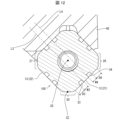
- Fig. 12 is a cross-sectional view taken along line XII-XII in Fig. 11 .
- the first side surface 21 may have a third recess 33 and a fourth recess 34 located closer to the second corner side surface 24 than the third recess 33.
- the distance from the third recess 33 to the first corner side surface 23 may be a third distance D3
- the distance from the fourth recess 34 to the second corner side surface 24 may be a fourth distance D4
- the width of the third recess 33 may be a third width W3
- the width of the fourth recess 34 may be a fourth width W4
- the third width W3 and the fourth width W4 may be smaller than the third distance D3 and the fourth distance D4.
- the third distance D3 may be the shortest distance between the third recess 33 and the first corner side 23 in a direction parallel to the top surface 11.
- the fourth distance D4 may be the shortest distance between the fourth recess 34 and the second corner side 24 in a direction parallel to the top surface 11.
- the third recess 33 and the fourth recess 34 may be positioned rotationally symmetrical with respect to the center CY (indicated by a dot in the figure) of the first side surface 21.
- the cutting insert 10C is an insert that can be used upside down, the positions of the third recess 33 and the fourth recess 34 do not change even if the cutting insert 10C is installed upside down. This simplifies the task of gripping the cutting insert 10C with a robot hand, and simplifies the movement of the device, making it possible to avoid complicating the device.
- the cutting insert 10C may have the third recess 33 and the fourth recess 34 at the same position in the vertical direction from the upper surface 11 to the lower surface 12.
- the positions of the third recess 33 and the fourth recess 34 do not change even if the cutting insert 10C is rotated at a fixed angle and attached. This simplifies the task of gripping the cutting insert 10C with a robot hand, and simplifies the movement of the device, thereby avoiding the device from becoming complicated.
- the third recess 33 and the fourth recess 34 may be formed on each side surface except the corner side surface.
- the cutting insert 10C may be configured such that, in the vertical direction from the upper surface 11 to the lower surface 12, the width from the third recess 33 to the upper surface 11 is a fourth height H4, the width from the third recess 33 to the lower surface 12 is a fifth height H5, and the width of the third recess 33 is a sixth height H6, with the sixth height H6 being smaller than the fourth height H4 and the fifth height H5.
- the cutting insert 10C can provide the third recess 33 while ensuring the distance between the upper surface 11, where the upper cutting edge 16 is located at its intersection with the side surface 13, and the lower surface 12, where the lower cutting edge 17 is located, and the third recess 33, thereby ensuring the strength of the upper cutting edge 16 and the lower cutting edge 17.
- the cutting insert 10C may be configured such that, in the vertical direction from the upper surface 11 to the lower surface 12, the width from the fourth recess 34 to the upper surface 11 is a first height H7, the width from the fourth recess 34 to the lower surface 12 is an eighth height H8, and the width of the fourth recess 34 is a ninth height H9, with the ninth height H9 being smaller than the seventh height H7 and the eighth height H8.
- the fourth recess 34 By configuring in this way, even while providing the fourth recess 34, the distance between the upper surface 11 where the upper cutting edge 16 is located and the lower surface 12 where the lower cutting edge 17 is located at the intersection with the side surface 13 is secured, and the fourth recess 34 can be secured, thereby ensuring the strength of the upper cutting edge 16 and the lower cutting edge 17.
- the first corner side surface 23 may have a linear or convex shape in a cross section passing through the first corner side surface 23 and perpendicular to the top surface 11. In other words, the first corner side surface 23 does not have a recess into which the claws of a robot hand can be inserted.
- This configuration reduces the risk of a decrease in the durability of the cutting insert 10.
- the third recess 33 has a third wall surface 33a located on the side of the fourth recess 34
- the fourth recess 34 has a fourth wall surface 34a located on the side of the third recess 33.
- an extension line L3 of the third wall surface 33a and an extension line L4 of the fourth wall surface 34a may be parallel to each other, or may have an inclination that intersects on the side where the center of the top surface 11 is located.
- the center of the top surface 11 may be the insert central axis CS.
- the claws of the robot hand are inserted into the third recess 33 and the fourth recess 34 from the front side of the first side surface 21, and the claws come into contact with the third wall surface 33a and the fourth wall surface 34a to grip the insert.
- the third wall surface 33a and the fourth wall surface 34a that the claws contact are parallel or have an inclination that approaches each other toward the side where the center of the upper surface 11 is located, so that the claws can easily grip the third wall surface 33a and the fourth wall surface 34a.
- the above configuration is effective when the cutting insert 10C is grasped by narrowing the gap between a pair of claws on the robot hand when the cutting insert 10C is grasped with a robot hand.
- the extension line L3 of the third wall surface 33a and the extension line L4 of the fourth wall surface 34a may be inclined so as to move away from each other on the side where the center of the upper surface 11 is located in a cross section parallel to the upper surface 11.
- the first side surface 21 may have a fifth recess 35 and a sixth recess 36 located closer to the lower surface 12 than the fifth recess 35.
- the fifth recess 35 and the sixth recess 36 may be located rotationally symmetrically with respect to the center CY of the first side surface 21.
- the second side surface 22 may have a third recess 33, a fourth recess 34, a fifth recess 35, and a sixth recess 36.
- the third recess 33 to the sixth recess 36 located on the first side surface 21 and the third recess 33 to the sixth recess 36 located on the second side surface 22 may be positioned rotationally symmetrically with respect to the center CZ of the first corner side surface 23.
- the third recess 33 to the sixth recess 36 may be formed on each side surface except the corner side surface.
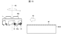
- Fig. 13 to Fig. 15 are schematic diagrams for explaining a method for manufacturing a machined product according to an embodiment of the present disclosure.
- Fig. 13 to Fig. 15 illustrate a cutting tool 1 according to an embodiment of the present disclosure.
- the manufacturing method of the machined product according to the embodiment of the present disclosure is a manufacturing method for manufacturing the machined product M by cutting the workpiece W using a cutting tool 1, and may include a first step, a second step, and a third step.
- the first step is a step of rotating the cutting tool 1.
- the second step is a step of bringing the rotating cutting tool 1 into contact with the workpiece W.
- the third step is a step of separating the cutting tool 1 from the workpiece W.
- Examples of the material of the workpiece W include aluminum alloy, stainless steel, carbon steel, alloy steel, cast iron, and non-ferrous metal.
- the specific content of the manufacturing method of the machined product according to the embodiment of the present disclosure is as follows.
- the cutting tool 1 is rotated in the rotation direction T while being moved in the direction of the arrow FD to approach the workpiece W. Then, the cutting insert 10 of the rotating cutting tool 1 is moved in the direction of the arrow FD while being brought into contact with the workpiece W. As a result, the cutting tool 1 cuts the workpiece W, and as shown in the example in Figure 15, a machined surface Wf is formed on the workpiece.
- the cutting tool 1 is further moved in the direction of the arrow FD to separate it from the workpiece W. This completes the cutting of the workpiece W, and a machined product M can be produced, which is the workpiece W that has been machined.
- the cutting insert 10 of the cutting tool 1 can be repeatedly brought into contact with different locations on the workpiece W while rotating the cutting tool 1.
- the cutting tool 1 is equipped with a cutting insert that is easy to automatically replace while ensuring durability. This improves productivity and reduces manufacturing costs.
- the manufacturing method of the machined product according to the present disclosure is a manufacturing method for manufacturing a machined product by cutting the workpiece using a cutting tool, and may include a step of rotating the workpiece, a step of bringing the cutting tool according to the present disclosure into contact with the rotating workpiece, and a step of moving the cutting tool according to the present disclosure away from the workpiece.
- a cutting tool 1 is exemplified, but as described above, examples of cutting tools include rotary tools and turning tools.
- Rotary tools include, for example, cutting tools (milling tools). Turning tools are used for turning processes such as face milling and end milling. Examples of turning tools include external diameter machining tools, internal diameter machining tools, grooving tools, and cut-off tools.
- Cutting tool 3 31, 32, 32A, 32B Second recess 10, 10A, 10B, 10C Cutting insert 11 Upper surface 12 Lower surface 13 Side surface 14 Mounting hole 16 Upper cutting edge 17 Lower cutting edge 20 First corner 21 First side surface 22 Second side surface 23 First corner side surface 24 Second corner side surface 26 Second corner 31, 31A, 31B, First recess 31a First wall surface 32, 32A, 32B, Second recess 32a Second wall surface 33 Third recess 33a Third wall surface 34 Fourth recess 34a Fourth wall surface 40 Holder 42 Pocket D1 First interval D2 Second interval D3 Third interval D4 Fourth interval CS Central axis (center of upper surface) CY Center of first side surface CZ Center of first corner side surface H1 First height H2 Second height H3 Third height H4 Fourth height H5 Fifth height H6 Sixth height L1, L2, L3, L4 Extension line RS Rotation axis W1 First width W2 Second width W3 Third width W4 Fourth width Wf Machining surface
Landscapes
- Engineering & Computer Science (AREA)
- Mechanical Engineering (AREA)
- Milling Processes (AREA)
- Cutting Tools, Boring Holders, And Turrets (AREA)
Priority Applications (3)
| Application Number | Priority Date | Filing Date | Title |
|---|---|---|---|
| DE112024001523.9T DE112024001523T5 (de) | 2023-03-30 | 2024-01-09 | Schneideinsatz, schneidwerkzeug und verfahren zur herstellung eines maschinell bearbeiteten produkts |
| JP2025509767A JPWO2024202377A1 (https=) | 2023-03-30 | 2024-01-09 | |
| CN202480020918.4A CN120897814A (zh) | 2023-03-30 | 2024-01-09 | 切削刀片、切削刀具及切削加工物的制造方法 |
Applications Claiming Priority (2)
| Application Number | Priority Date | Filing Date | Title |
|---|---|---|---|
| JP2023-056533 | 2023-03-30 | ||
| JP2023056533 | 2023-03-30 |
Publications (1)
| Publication Number | Publication Date |
|---|---|
| WO2024202377A1 true WO2024202377A1 (ja) | 2024-10-03 |
Family
ID=92904818
Family Applications (1)
| Application Number | Title | Priority Date | Filing Date |
|---|---|---|---|
| PCT/JP2024/000094 Ceased WO2024202377A1 (ja) | 2023-03-30 | 2024-01-09 | 切削インサート、切削工具及び切削加工物の製造方法 |
Country Status (4)
| Country | Link |
|---|---|
| JP (1) | JPWO2024202377A1 (https=) |
| CN (1) | CN120897814A (https=) |
| DE (1) | DE112024001523T5 (https=) |
| WO (1) | WO2024202377A1 (https=) |
Citations (7)
| Publication number | Priority date | Publication date | Assignee | Title |
|---|---|---|---|---|
| JPH08505814A (ja) * | 1993-01-27 | 1996-06-25 | サンドビック アクティエボラーグ | 螺旋状に捩られた逃げ面とこれに接続した凹所を有する切削インサート |
| JP2004520181A (ja) * | 2001-01-25 | 2004-07-08 | イスカーリミテッド | 切削インサート |
| WO2010024435A1 (ja) * | 2008-08-29 | 2010-03-04 | 京セラ株式会社 | 切削インサートおよび切削工具並びにそれを用いた切削方法 |
| WO2013180160A1 (ja) * | 2012-05-30 | 2013-12-05 | 京セラ株式会社 | 切削インサート、切削工具および被削加工物の製造方法 |
| JP2014502927A (ja) * | 2011-01-27 | 2014-02-06 | デグテック リミテッド | 接線方向切削インサート |
| JP2022138402A (ja) * | 2021-03-10 | 2022-09-26 | 株式会社タンガロイ | 切削インサート及び旋削工具 |
| JP2023062610A (ja) * | 2021-10-21 | 2023-05-08 | 大同特殊鋼株式会社 | チップ脱着装置およびスローアウェイチップのコーナチェンジ方法 |
Family Cites Families (1)
| Publication number | Priority date | Publication date | Assignee | Title |
|---|---|---|---|---|
| JP5040589B2 (ja) | 2007-10-30 | 2012-10-03 | 株式会社タンガロイ | スローアウェイチップおよびこれを用いたスローアウェイ式切削工具 |
-
2024
- 2024-01-09 JP JP2025509767A patent/JPWO2024202377A1/ja active Pending
- 2024-01-09 DE DE112024001523.9T patent/DE112024001523T5/de active Pending
- 2024-01-09 CN CN202480020918.4A patent/CN120897814A/zh active Pending
- 2024-01-09 WO PCT/JP2024/000094 patent/WO2024202377A1/ja not_active Ceased
Patent Citations (7)
| Publication number | Priority date | Publication date | Assignee | Title |
|---|---|---|---|---|
| JPH08505814A (ja) * | 1993-01-27 | 1996-06-25 | サンドビック アクティエボラーグ | 螺旋状に捩られた逃げ面とこれに接続した凹所を有する切削インサート |
| JP2004520181A (ja) * | 2001-01-25 | 2004-07-08 | イスカーリミテッド | 切削インサート |
| WO2010024435A1 (ja) * | 2008-08-29 | 2010-03-04 | 京セラ株式会社 | 切削インサートおよび切削工具並びにそれを用いた切削方法 |
| JP2014502927A (ja) * | 2011-01-27 | 2014-02-06 | デグテック リミテッド | 接線方向切削インサート |
| WO2013180160A1 (ja) * | 2012-05-30 | 2013-12-05 | 京セラ株式会社 | 切削インサート、切削工具および被削加工物の製造方法 |
| JP2022138402A (ja) * | 2021-03-10 | 2022-09-26 | 株式会社タンガロイ | 切削インサート及び旋削工具 |
| JP2023062610A (ja) * | 2021-10-21 | 2023-05-08 | 大同特殊鋼株式会社 | チップ脱着装置およびスローアウェイチップのコーナチェンジ方法 |
Also Published As
| Publication number | Publication date |
|---|---|
| JPWO2024202377A1 (https=) | 2024-10-03 |
| DE112024001523T5 (de) | 2026-04-30 |
| CN120897814A (zh) | 2025-11-04 |
Similar Documents
| Publication | Publication Date | Title |
|---|---|---|
| JP4833887B2 (ja) | タレット刃物台及び工作機械 | |
| JP6524590B2 (ja) | 切削工具及び工具本体 | |
| EP3466574B1 (en) | Vibration cutting insert | |
| KR102745530B1 (ko) | 회전 공구 및 절삭 가공물의 제조 방법 | |
| CN110214064B (zh) | 加工沟槽的方法 | |
| JP6052455B1 (ja) | 切削インサートおよび切削工具 | |
| KR20120116933A (ko) | 절삭 인서트, 시트 부재, 및 블레이트 팁 교환 절삭 공구 | |
| WO2024202377A1 (ja) | 切削インサート、切削工具及び切削加工物の製造方法 | |
| JPWO2024202377A5 (https=) | ||
| US12202052B2 (en) | Boring tool holder and turning tool | |
| JP7114733B2 (ja) | 切削インサート、切削工具及び切削加工物の製造方法 | |
| US20210197298A1 (en) | Cutting insert adaptor and tool assembly | |
| JP7827726B2 (ja) | 金属切削旋削工具 | |
| KR102540681B1 (ko) | 절삭 인서트, 절삭 공구 및 절삭 가공물의 제조 방법 | |
| KR100296445B1 (ko) | 작은 구멍의 내경 가공을 위한 인덱서블 보링공구 | |
| JP7706641B2 (ja) | 切削インサート、切削工具、及び切削加工物の製造方法 | |
| JP2006326720A (ja) | スローアウェイチップおよび切削工具 | |
| JP5678431B2 (ja) | 刃先交換式溝入れ工具及び周面溝入れ加工方法 | |
| JP2002355702A (ja) | 切削工具 | |
| US20240051036A1 (en) | Metal cutting turning tool | |
| JP2014168817A (ja) | 刃先交換式切削工具 | |
| JP6959117B2 (ja) | 加工用工具及び加工装置並びに加工方法 | |
| WO2024202342A1 (ja) | 切削工具及び切削加工物の製造方法 | |
| JP5526804B2 (ja) | 刃先交換式溝入れ工具及び周面溝入れ加工方法 | |
| JPH10249612A (ja) | バイトホルダ |
Legal Events
| Date | Code | Title | Description |
|---|---|---|---|
| 121 | Ep: the epo has been informed by wipo that ep was designated in this application |
Ref document number: 24778523 Country of ref document: EP Kind code of ref document: A1 |
|
| ENP | Entry into the national phase |
Ref document number: 2025509767 Country of ref document: JP Kind code of ref document: A |
|
| WWE | Wipo information: entry into national phase |
Ref document number: 2025509767 Country of ref document: JP |
|
| WWE | Wipo information: entry into national phase |
Ref document number: 202480020918.4 Country of ref document: CN |
|
| WWE | Wipo information: entry into national phase |
Ref document number: 112024001523 Country of ref document: DE |
|
| WWP | Wipo information: published in national office |
Ref document number: 202480020918.4 Country of ref document: CN |
|
| 122 | Ep: pct application non-entry in european phase |
Ref document number: 24778523 Country of ref document: EP Kind code of ref document: A1 |