WO2024202111A1 - フロントフード用ラッチ装置 - Google Patents
フロントフード用ラッチ装置 Download PDFInfo
- Publication number
- WO2024202111A1 WO2024202111A1 PCT/JP2023/032815 JP2023032815W WO2024202111A1 WO 2024202111 A1 WO2024202111 A1 WO 2024202111A1 JP 2023032815 W JP2023032815 W JP 2023032815W WO 2024202111 A1 WO2024202111 A1 WO 2024202111A1
- Authority
- WO
- WIPO (PCT)
- Prior art keywords
- latch
- pole
- front hood
- primary
- vehicle
- Prior art date
- Legal status (The legal status is an assumption and is not a legal conclusion. Google has not performed a legal analysis and makes no representation as to the accuracy of the status listed.)
- Ceased
Links
Images


Classifications
-
- B—PERFORMING OPERATIONS; TRANSPORTING
- B62—LAND VEHICLES FOR TRAVELLING OTHERWISE THAN ON RAILS
- B62D—MOTOR VEHICLES; TRAILERS
- B62D25/00—Superstructure or monocoque structure sub-units; Parts or details thereof not otherwise provided for
- B62D25/08—Front or rear portions
- B62D25/10—Bonnets or lids, e.g. for trucks, tractors, busses, work vehicles
- B62D25/12—Parts or details thereof
-
- E—FIXED CONSTRUCTIONS
- E05—LOCKS; KEYS; WINDOW OR DOOR FITTINGS; SAFES
- E05B—LOCKS; ACCESSORIES THEREFOR; HANDCUFFS
- E05B77/00—Vehicle locks characterised by special functions or purposes
- E05B77/54—Automatic securing or unlocking of bolts triggered by certain vehicle parameters, e.g. exceeding a speed threshold
-
- E—FIXED CONSTRUCTIONS
- E05—LOCKS; KEYS; WINDOW OR DOOR FITTINGS; SAFES
- E05B—LOCKS; ACCESSORIES THEREFOR; HANDCUFFS
- E05B81/00—Power-actuated vehicle locks
- E05B81/12—Power-actuated vehicle locks characterised by the function or purpose of the powered actuators
- E05B81/20—Power-actuated vehicle locks characterised by the function or purpose of the powered actuators for assisting final closing or for initiating opening
-
- E—FIXED CONSTRUCTIONS
- E05—LOCKS; KEYS; WINDOW OR DOOR FITTINGS; SAFES
- E05B—LOCKS; ACCESSORIES THEREFOR; HANDCUFFS
- E05B83/00—Vehicle locks specially adapted for particular types of wing or vehicle
- E05B83/16—Locks for luggage compartments, car boot lids or car bonnets
-
- E—FIXED CONSTRUCTIONS
- E05—LOCKS; KEYS; WINDOW OR DOOR FITTINGS; SAFES
- E05B—LOCKS; ACCESSORIES THEREFOR; HANDCUFFS
- E05B83/00—Vehicle locks specially adapted for particular types of wing or vehicle
- E05B83/16—Locks for luggage compartments, car boot lids or car bonnets
- E05B83/24—Locks for luggage compartments, car boot lids or car bonnets for car bonnets
Definitions
- the present invention relates to a front hood latch device, and in particular to a front hood latch device that controls the opening and closing of a front hood that opens and closes a front trunk located at the front of a vehicle body.
- Some vehicles such as electric vehicles and rear-engine vehicles with engines mounted at the rear of the vehicle body, use the front of the vehicle body as a front trunk.
- This type of vehicle is provided with two latch mechanisms to prevent the front hood from opening accidentally while driving, and is configured so that the two latch mechanisms are released only when the vehicle is stopped (see, for example, Patent Document 1).
- the front hood for opening and closing the front trunk is opened and closed more frequently than the front hood for opening and closing the engine compartment.
- it is necessary to constantly perform an operation to release the two latch mechanisms, which makes the operation of opening the front hood complicated.
- the present invention aims to provide a front hood latch device that improves operability and prevents the front hood from opening unintentionally while driving.
- the front hood latch device of the present invention is characterized in that it comprises: a latch that is provided on the vehicle body and can engage with a striker at the front of the front hood when the front hood is closed; a biasing member that biases the latch in a disengaging direction; a primary pole that maintains the front hood in a fully closed position by engaging with the latch when the latch that has engaged with the striker is positioned at a predetermined primary latch position; a secondary pole that maintains the front hood in a half-closed position by engaging with the latch when the latch that has been disengaged from the primary pole is positioned at a predetermined secondary latch position; and an actuator unit that can release the engagement between the primary pole and the latch when operated in the open direction, and is characterized in that it operates the actuator unit in the open direction when an open command is given while the vehicle is stopped, and maintains the actuator unit in a stopped state when an open command is given while the vehicle is moving.
- the present invention is also characterized in that, in the above-mentioned front hood latch device, it is provided with an operation transmission unit inside the front trunk that operates the primary pole in a direction to release the engagement with the latch when an operation unit inside the front trunk provided inside the front trunk that can be opened and closed by the front hood is operated, and when the primary pole operates in the direction to release the engagement with the latch, it operates the secondary pole in the direction to release the engagement with the latch, provided that the vehicle is stopped.
- the present invention is also characterized in that, in the above-mentioned front hood latch device, it is provided with an in-vehicle operation transmission unit that operates the secondary pole in a direction to release the engagement state with the latch when an in-vehicle operation unit provided in the vehicle cabin is operated, and the in-vehicle operation unit is provided in a position where it cannot be operated while the vehicle is moving.
- the present invention also provides the front hood latch device described above, which includes an in-vehicle operation transmission unit that operates the secondary pole in a direction to release the engagement with the latch when an in-vehicle operation unit provided in the vehicle cabin is operated, and the in-vehicle operation transmission unit has a transmission switching unit that switches between an ON state in which the operation of the in-vehicle operation unit can be transmitted to the secondary pole and an OFF state in which the operation of the in-vehicle operation unit cannot be transmitted to the secondary pole, and the transmission switching unit is in the ON state only when the vehicle is not moving.
- the present invention is also characterized in that the front hood latch device described above includes a close operation transmission unit that operates the latch toward the primary latch position when the actuator unit operates in the close direction with the latch disposed in the secondary latch position.
- the present invention is also characterized in that, in the front hood latch device described above, the actuator unit is operated in the closing direction on the condition that the front hood has moved from an open state in the closing direction and the latch has been placed in the secondary latch position.
- the present invention is also characterized in that, in the front hood latch device described above, an interlocking link portion is provided between the primary pole and the secondary pole, which interlocks the primary pole or the secondary pole when either one of the poles moves in a direction to release the engagement with the latch.
- the interlocking link portion includes a link bar that links the primary pole and the secondary pole, and the link bar is arranged to interlock the primary pole in a direction that disengages the latch when the secondary pole moves in a direction that disengages the latch, and to maintain the secondary pole engaged with the latch when the primary pole moves in a direction that disengages the latch.
- the present invention is also characterized in that the above-mentioned front hood latch device is provided with an open operation transmission part that operates the secondary pole in a direction to release the engagement with the latch when the actuator unit operates in the open direction.
- the present invention is also characterized in that in the front hood latch device described above, a housing member that houses the latch is provided with a guide portion along the movement path of the closing operation transmission portion.
- the present invention is also characterized in that the front hood latch device described above is provided with a canceling unit that releases the engagement between the closing operation transmission unit and the latch when an emergency operating force is input.
- the present invention is also characterized in that in the above-mentioned front hood latch device, the cancel portion includes a cancel lever that operates integrally with the secondary pole.
- the present invention also provides the front hood latch device described above, characterized in that the actuator unit includes a drive source and a reduction mechanism, at least some of the components of the reduction mechanism are arranged in a position overlapping the latch in the direction of the latch's operating axis, the drive source and the output part of the reduction mechanism are arranged in positions surrounding the latch in the direction of the latch's operating axis, a circuit board equipped with a controller for controlling the operation of the actuator unit is arranged between the drive source and the output part of the reduction mechanism in the direction of the latch's operating axis and in a position overlapping the latch, the primary pole, and the secondary pole, and a status detection sensor is provided on the circuit board to detect the status of the latch, the primary pole, and the secondary pole.
- the actuator unit includes a drive source and a reduction mechanism, at least some of the components of the reduction mechanism are arranged in a position overlapping the latch in the direction of the latch's operating axis, the drive source and the output part of the reduction mechanism are arranged
- a primary pole and a secondary pole are provided that engage with a latch, and when a command transmission unit such as a key FOB is operated, the actuator unit operates to release the engagement between the primary pole and the latch, provided that the vehicle is stopped. This means that even if the command transmission unit is operated while the vehicle is moving, there is no risk of the front hood opening inadvertently, ensuring safety and improving operability.
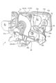
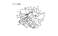
- FIG. 1 is a perspective view of a front hood latch device according to an embodiment of the present invention, as viewed from the base plate side.
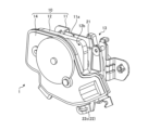
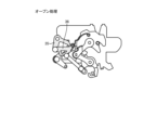
- FIG. 2 is a perspective view of the front hood latch device shown in FIG. 1 as viewed from the cover side.
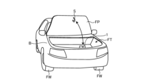
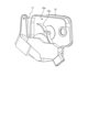
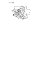
- FIG. 3 is a perspective view of a vehicle to which the front hood latch device shown in FIG. 1 is applied, as viewed from the front side.
- FIG. 4 is a diagram showing the internal structure of the front hood latch device shown in FIG. 1 with the cover and case omitted.
- FIG. 5 is a diagram in which the cinching lever and the cancel lever are omitted from FIG. FIG.
- FIG. 6 is a diagram showing the positions of the latch, the primary pole, the secondary pole, the link bar, the cancel lever, and the open lever in the front hood latch device shown in FIG. 1, as viewed from the base plate side.
- FIG. 7 is a perspective view of FIG.
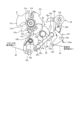
- FIG. 8 is a diagram showing an actuator unit applied to the front hood latch device shown in FIG.
- FIG. 9 is a perspective view of a case that is applied to the front hood latch device shown in FIG.
- FIG. 10 is a block diagram showing a control system of the front hood latch device shown in FIG.
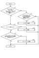
- FIG. 11 is a flowchart showing the contents of the process executed by the controller shown in FIG.
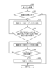
- FIG. 12 is a flow chart showing the contents of the cinching process shown in FIG. FIG.
- FIG. 13 is a flowchart showing the contents of the open process shown in FIG.
- FIG. 14 is a flow chart showing the contents of the emergency process shown in FIG.
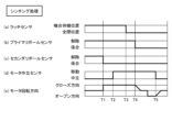
- FIG. 15 is a timing chart showing the operation timing of the latch sensor, the primary pole sensor, the secondary pole sensor, the motor neutral sensor, and the motor rotation direction in the cinching process shown in FIG.
- FIG. 16 is a timing chart showing the operation timing of the latch sensor, the primary pole sensor, the secondary pole sensor, the motor neutral sensor, and the motor rotation direction in the open process shown in FIG.
- FIG. 17A sequentially illustrates the operation of the front hood latch device in the cinching process shown in FIG. 11, with the latch in the engagement standby state.
- FIG. 17B sequentially illustrates the operation of the front hood latch device in the cinching process illustrated in FIG. 11, showing the state in which the striker has entered the striker entrance groove.
- FIG. 17C sequentially illustrates the operation of the front hood latch device in the cinching process illustrated in FIG. 11, showing the state in which the striker has entered the striker entrance groove.
- FIG. 17D sequentially illustrates the operation of the front hood latch device in the cinching process shown in FIG. 11, showing the state in which the open lever has rotated in the cinching direction.
- FIG. 17E sequentially illustrates the operation of the front hood latch device in the cinching process shown in FIG. 11, showing the state in which the primary pole is engaged with the latch.
- FIG. 17F sequentially illustrates the operation of the front hood latch device in the cinching process shown in FIG. 11, showing the state in which the open lever has returned to the neutral position.
- FIG. 18A sequentially illustrates the operation of the front hood latch device in the opening process shown in FIG. 11, showing a state in which the latch engaged with the striker is in the primary latch position.
- FIG. 18B sequentially illustrates the operation of the front hood latch device in the opening process shown in FIG. 11, showing the state in which the open lever has rotated in the release direction.
- FIG. 18C sequentially illustrates the operation of the front hood latch device in the opening process shown in FIG. 11, showing the state in which the secondary pole has rotated in the direction to release the engagement with the latch.
- FIG. 18A sequentially illustrates the operation of the front hood latch device in the opening process shown in FIG. 11, showing a state in which the latch engaged with the striker is in the primary latch position.
- FIG. 18B sequentially illustrates the operation of the front hood latch device in
- FIG. 19A is a conceptual diagram showing the operation of a transmission switching unit provided in a transmission path from an operation unit inside the vehicle compartment to a secondary pole in an ON state.
- FIG. 19B is a conceptual diagram showing the operation of the transmission switching unit provided in the transmission path from the operation unit inside the vehicle interior to the secondary pole in the OFF state.
- FIG. 19C is a conceptual diagram showing the operation of the transmission switching unit provided in the transmission path from the operation unit inside the vehicle interior to the secondary pole in the OFF state.
- FIG. 1 and 2 show a front hood latch device 1 according to an embodiment of the present invention.
- the front hood latch device 1 illustrated here is intended for use in four-wheeled vehicles such as electric vehicles equipped with a front trunk (hereinafter sometimes referred to as frunk FT) between the left and right front wheels FW in front of the vehicle body B, as shown in FIG. 3, and controls the opening and closing of the front hood FP, which opens and closes the upper opening of the frunk FT.
- a striker S is provided at the lower front edge of the front hood FP.
- the front hood latch device 1 maintains the front hood FP in a closed state relative to the vehicle body B or controls the frunk FT to open by switching between an engaged state with the striker S and a disengaged state.
- the specific configuration of the front hood latch device 1 will be described in detail below. For convenience, the respective directions will be specified in the posture in which the device is mounted on the vehicle body B.
- the front hood latch device 1 includes a latch 21, a primary pole 22, a secondary pole 23, an emergency lever 24, and a cancel lever 25 inside a housing member 10.
- the housing member 10 includes a base plate 11, a case 12, and a cover 14.
- the base plate 11 is a plate-like member formed from steel.
- the case 12 is formed from resin, and is configured so that the inner surface 12a covers one surface 11a of the base plate 11.
- the cover 14 is for covering an actuator unit 40, which will be described later.
- a striker entry groove 13 is formed on one side of the upper portion of the base plate 11 and the case 12.
- the striker entry groove 13 is a cutout into which the striker S enters when the front hood FP is closed against the flank FT, and is formed to extend in the vertical direction and open at the upper edges of the base plate 11 and the case 12.
- the striker entry groove 13 is sized to a length that allows the front hood FP to be placed in a fully closed position relative to the frunk FT.
- the latch 21, primary pole 22, secondary pole 23 and emergency lever 24 are each supported on the base plate 11 via individual support shafts, and can rotate around axes that are parallel to each other.
- the support shaft of the latch 21 (hereinafter referred to as the latch shaft 21a) is provided on the side of the striker entry groove 13.
- the support shaft of the primary pole 22 (hereinafter referred to as the primary shaft 22a) is provided on the part below the latch shaft 21a around the latch 21, and the support shaft of the secondary pole 23 (hereinafter referred to as the secondary shaft 23a) is provided on the part between the latch shaft 21a and the primary shaft 22a around the latch 21.
- the support shaft of the emergency lever 24 (hereinafter referred to as the emergency support shaft 24a) is provided on a part that is approximately the same height as the secondary shaft 23a, at a position farther away from the latch 21 than the secondary shaft 23a.
- the cancel lever 25 is attached to the edge of the secondary shaft 23a that is closer to the case 12 than the secondary pole 23, and can rotate together with the secondary pole 23.
- the latch 21 engages with the striker S and has a striker abutment portion 21b and a hook portion 21c on the outer periphery.
- the striker abutment portion 21b and the hook portion 21c extend radially from the latch shaft 21a and can be positioned across the striker entry groove 13 of the base plate 11, and are adjacent to each other with a storage groove 21d between them that can accommodate the striker S.
- the latch 21 is constantly biased in the release direction (counterclockwise in FIG. 4) by the biasing force of a latch spring (biasing member) 21e provided between the latch 21 and the base plate 11 so as to return to a predetermined meshing standby state.
- the meshing standby state is a state in which the hook portion 21c retreats to the side relative to the striker entry groove 13, while the striker abutment portion 21b is positioned across the striker entry groove 13 and the opening of the storage groove 21d is aligned with the striker entry groove 13. Therefore, in the engagement standby state, when the front hood FP is closed, the striker S can enter the striker entrance groove 13. When the front hood FP moves further in the closing direction, the striker S that has entered the striker entrance groove 13 abuts against the striker abutment portion 21b, causing the latch 21 to rotate in the engagement direction (clockwise in FIG. 4) against the biasing force of the latch spring 21e, and the striker S is accommodated in the accommodation groove 21d, with the hook portion 21c positioned across the open end side of the striker entrance groove 13.
- the latch 21 is provided with a latch pin 21f and a latch detection magnet 21g.
- the latch pin 21f protrudes toward the case 12 from the surface of the latch 21 facing the case 12 (hereinafter referred to as the case facing surface 21h), and is provided in a portion that is above the latch shaft 21a when the latch 21 is placed in the primary latch position.
- the primary latch position of the latch 21 is a position in which the latch 21 is placed in a state in which the hook portion 21c crosses the striker entry groove 13 with the accommodation groove 21d of the latch 21 positioned below the striker entry groove 13.
- the latch detection magnet 21g is for detecting the rotation state of the latch 21 by a magnet sensor described later.
- the latch detection magnet 21g is attached to a portion of the case facing surface 21h of the latch 21 that corresponds to the latch pin 21f across the latch shaft 21a, that is, a portion that is below the latch shaft 21a when the latch 21 is placed in the primary latch position.
- the primary pole 22 and secondary pole 23 each engage with the latch 21, preventing the latch 21 from rotating in the release direction against the biasing force of the latch spring 21e, and stopping it at the desired position.
- the primary pole 22 is configured to engage with the primary engagement portion 21j of the latch 21 when the latch 21 is placed in the primary latch position, thereby preventing the latch 21 from rotating in the release direction.
- a primary spring 22b that constantly urges the primary pole 22 in the engagement direction is provided between the primary pole 22 and the base plate 11.
- a flank cable connection portion 22c is provided on this primary pole 22.
- the flank cable connection portion 22c extends radially, with its extended end extending to a position beyond the base plate 11.
- a flank cable (front trunk internal operation transmission portion) 32 that links with the flank internal operation portion (front trunk internal operation portion) 31 is connected to this flank cable connection portion 22c.
- the flank internal operation portion 31 is an operation portion that can be operated from inside the flank FT when the front hood FP is closed. When the flank internal operating part 31 is operated, the operating force is transmitted to the primary pole 22 via the flank cable 32, and the primary pole 22 can be rotated in a direction that releases the engagement with the latch 21 against the biasing force of the primary spring 22b
- the secondary pawl 23 is configured to engage with the secondary engagement portion 21k of the latch 21 to prevent the latch 21 from rotating in the release direction when the accommodation groove 21d of the latch 21 is positioned above the striker entry groove 13 and the hook portion 21c is positioned across the striker entry groove 13 (secondary latch position of the latch 21).
- the front hood FP When the striker S is accommodated in the accommodation groove 21d and the latch 21 is arranged in the primary latch position, the front hood FP is arranged in a fully closed position relative to the frunk FT, and when the striker S is accommodated in the accommodation groove 21d and the latch 21 is arranged in the secondary latch position, the front hood FP is arranged in a slightly open position relative to the frunk FT (front hood FP half-engaged position).
- a secondary spring 23b that constantly biases the secondary pole 23 in the engagement direction is provided between the secondary pole 23 and the base plate 11.
- This secondary pole 23 is provided with an actuator input portion 23c.
- the actuator input portion 23c abuts against the open lever 35 when the open lever 35 described later rotates in the release direction (clockwise in FIG. 4), and rotates the secondary pole 23 in a direction to release the engagement state with the latch 21 against the biasing force of the secondary spring 23b.
- a link bar (interlocking link portion) 26 is provided between the primary pole 22 and the secondary pole 23.
- the link bar 26 interlocks the primary pole 22 when the secondary pole 23 rotates in a direction to release the engagement with the latch 21, and links the secondary pole 23 to maintain the state of engagement with the latch 21 when the primary pole 22 rotates in a direction to release the engagement with the latch 21.
- one end of the link bar 26 is rotatably supported by the lever link portion 23d of the secondary pole 23, and the other end of the link bar 26 is rotatably supported by the lever link portion 22d of the primary pole 22 via the long hole 26a.
- the lever link portion 23d of the secondary pole 23 protrudes from the outer circumferential surface of the secondary pole 23 toward the outer periphery
- the lever link portion 22d of the primary pole 22 protrudes from the outer circumferential surface of the primary pole 22 toward the outer periphery.
- the lever link portion 23d when the secondary pawl 23 is in contact with the outer circumferential surface of the latch 21, the lever link portion 23d is provided so as to extend almost horizontally from the outer circumferential surface facing the emergency lever 24, and when the primary pawl 22 is in contact with the outer circumferential surface of the latch 21, the lever link portion 22d is provided so as to extend diagonally downward from the outer circumferential surface facing the emergency lever 24.
- a primary detection magnet 22f is provided on the case facing surface 22e of the primary pole 22 to detect the rotation state of the primary pole 22 using a magnet sensor described below
- a secondary detection magnet 23f is provided on the case facing surface 23e of the secondary pole 23 to detect the rotation state of the secondary pole 23 using a magnet sensor described below.
- the emergency lever 24 has a pole pressing portion 24b and a passenger compartment cable connection portion 24c.
- the pole pressing portion 24b and the passenger compartment cable connection portion 24c each extend radially from the emergency support shaft 24a.
- a lever spring 24d is provided between the emergency lever 24 and the base plate 11, which biases the emergency lever 24 counterclockwise in FIG. 4 and positions it in a predetermined standby position.
- the pole pressing portion 24b is positioned above the lever link portion 23d of the secondary pole 23 that abuts against the outer circumferential surface of the latch 21, and when rotated clockwise in FIG.
- An emergency cable (in-vehicle operation transmission unit) 34 that links with the in-vehicle operation unit (emergency operation unit) 33 is connected to the vehicle interior cable connection unit 24c.
- the in-vehicle operation unit 33 is an operation part that is provided in a position that cannot be operated while the vehicle is moving, such as at the back of the driver's feet in the vehicle interior.
- the cancel lever 25 When the secondary pole 23 is engaged with the latch 21, the cancel lever 25 extends from the secondary shaft 23a toward the latch shaft 21a and then bends upward.
- the extending edge of the cancel lever 25 is arc-shaped and is configured to be thicker than the base end.
- the case 12 is provided with an actuator unit 40, an open lever (open operation transmission part) 35, and a circuit board 50.
- the actuator unit 40 is provided with an electric motor (drive source) 41 that can rotate forward and backward, and a reduction mechanism that reduces the drive of the electric motor 41 and transmits it to the open lever 35, and is disposed on the outer surface 12b of the case 12.
- the reduction mechanism is provided with a worm gear 42 provided on the output shaft 41a of the electric motor 41, a first gear (worm wheel) 43 that meshes with the worm gear 42, a third gear 45 that meshes with a second gear 44 that is integral with the first gear 43, and a sector gear 47 that meshes with a fourth gear 46 that is integral with the third gear 45.
- the first gear 43 and the third gear 45 are rotatably supported on the case 12 via individual support shafts 43a and 45a that are parallel to the latch shaft 21a.
- the electric motor 41 is disposed on the outer periphery of the latch 21, and the first gear 43 and the third gear 45 are disposed at a position overlapping the case facing surface 21h of the latch 21.
- the sector gear 47 is rotatably supported on the case 12 via a cylindrical boss portion (output portion) 47a disposed in the center.
- the boss portion 47a of the sector gear 47 is disposed above the emergency support shaft 24a in a portion on the outer periphery of the latch 21 so as to be parallel to the emergency support shaft 24a.
- the open lever 35 is fixed to the boss portion 47a of the sector gear 47 and rotates integrally with the sector gear 47. It has a pressing lever portion 35a and a cinching connection portion 35b on the inner surface 12a side of the case 12.
- the pressing lever portion 35a extends radially from the rotation axis of the open lever 35, then bends toward the base plate 11, and the extending edge portion is further bent and extends in a direction perpendicular to the rotation axis of the open lever 35.
- the pressing lever portion 35a is located above the actuator input portion 23c provided on the secondary pole 23.
- the open lever 35 rotates in the release direction (clockwise in Figure 4) and rotates the secondary pole 23 in a direction to release the engagement state with the latch 21 via the actuator input portion 23c.
- the cinching connection 35b extends radially from the rotation axis of the open lever 35. When the open lever 35 is in the neutral position, the cinching connection 35b extends downward from the rotation axis of the open lever 35.
- the cinching connection 35b is rotatably connected to the cinching lever (close operation transmission part) 36 via the cinching support shaft 36a.
- the cinching support shaft 36a extends parallel to the rotation axis of the open lever 35.
- the cinching lever 36 extends from the cinching connection 35b to the latch pin 21f of the latch 21 between the case facing surface 21h of the latch 21 and the case 12, and has a guide pin 36b at its tip.
- the guide pin 36b extends from the cinching lever 36 toward the case 12.
- a guide rib (guide part) 12c is provided on the inner surface 12a of the case 12.
- the guide rib 12c guides the movement of the cinching lever 36 via the guide pin 36b when the open lever 35 rotates, and is molded integrally with the case 12.
- the guide rib 12c is provided so that when the open lever 35 rotates in the cinching direction (counterclockwise in FIG. 4), the extended end face of the cinching lever 36 abuts against the latch pin 21f, thereby rotating the latch 21 to the primary latch position against the biasing force of the latch spring 21e.
- the circuit board 50 is provided at a position between the electric motor 41 and the open lever 35 on the outer surface 12b of the case 12.
- the circuit board 50 is large enough to include all of the areas where the latch detection magnet 21g, primary detection magnet 22f, secondary detection magnet 23f, and open lever detection magnet 35c are provided, and is arranged at a position overlapping the latch 21, primary pole 22, and secondary pole 23 in the axial direction of the latch shaft 21a.
- a magnet sensor state detection sensor
- the magnet sensor detects the latch detection magnet 21g, primary detection magnet 22f, secondary detection magnet 23f, and open lever detection magnet 35c through the case 12.
- a magnet sensor (hereinafter referred to as the latch sensor 51) that detects whether the latch 21 is in the primary latch position is provided in correspondence with the latch detection magnet 21g.
- the magnet sensor (hereinafter referred to as the primary pole sensor 52) corresponding to the primary detection magnet 22f detects whether the primary pole 22 is engaged with the latch 21, and the magnet sensor (hereinafter referred to as the secondary pole sensor 53) corresponding to the secondary detection magnet 23f detects whether the secondary pole 23 is engaged with the latch 21.
- the magnet sensor (hereinafter referred to as the motor neutral sensor 54) corresponding to the open lever detection magnet 35c detects whether the open lever 35 is in the neutral position.
- the circuit board 50 is equipped with a processing device such as a CPU (Central Processing Unit) that constitutes the controller 100 described later, or hardware such as an IC (Integrated Circuit).
- FIG. 10 shows the control system of the front hood latch device 1.
- the controller 100 shown in FIG. 10 controls the driving of the electric motor 41 according to the programs and data stored in memory when output signals are given from the command sending unit 101, the vehicle speed sensor 102, the latch sensor 51, the primary pole sensor 52, the secondary pole sensor 53, and the motor neutral sensor 54.
- the command sending unit 101 outputs an open command to the controller 100 when opening the flank FT, and is, for example, a key FOB held by the vehicle owner or a front hood opening switch provided in the passenger compartment.
- the vehicle speed sensor 102 detects the speed of the vehicle and outputs the detection result to the controller 100.
- the controller 100 may be realized, for example, by having a processing device such as a CPU execute a program, i.e., by software, or it may be realized by hardware such as an IC, or it may be realized by using both software and hardware.
- a processing device such as a CPU execute a program
- hardware such as an IC
- the processing contents of the controller 100 will be described in detail below with reference to the flowcharts shown in Figures 11 to 14 and the timing charts shown in Figures 15 and 16 as appropriate.
- the latch 21 of the front hood latch device 1 is positioned in an engagement standby state by the latch spring 21e, as shown in Figure 17A, the open lever 35 is positioned in a neutral position, and the emergency lever 24 is positioned in an operation standby position.
- the primary pole 22 and secondary pole 23 are biased in the engagement direction by the primary spring 22b and secondary spring 23b, respectively, while abutting against the outer circumferential surface of the latch 21.
- the front hood latch device 1 when the latch 21 is placed in the primary latch position, the primary pole 22 engages with the latch 21, thereby preventing movement in the release direction. As a result, the front hood FP is maintained in the fully closed position in which the frunk FT is closed.
- the open lever 35 rotates in the cinching direction (T2 in Fig. 15), and the rotation of the open lever 35 proceeds with the cinching lever 36 in contact with the latch pin 21f, so that the cinching lever 36 moves along the guide rib 12c via the guide pin 36b, and the latch 21 is placed in the primary latch position.
- the primary pole 22 engages with the latch 21 and prevents it from moving in the release direction, so that the front hood FP is maintained in the fully closed position with the flank FT closed (T3 in Fig. 15).
- the controller 100 drives the electric motor 41 in the open direction until the open lever 35 returns to the neutral position, as shown in Fig. 17F (steps S13 to S15 in Fig. 12).
- the front hood latch device 1 operates to a position where the flank FT is completely closed, which is advantageous in terms of operability.
- the cinching lever 36 is rotatably supported on the cinching connection part 35b of the open lever 35, and is adapted to move along the guide rib 12c provided on the case 12. Therefore, by appropriately changing the extension length from the cinching connection part 35b and the path of the guide rib 12c, there is also the advantage that the force and path when pulling in the striker S can be easily adjusted.
- the cinching lever 36 is positioned so as to overlap the latch 21 in the direction along the latch shaft 21a, transmission loss can also be reduced.
- the open lever 35 rotates in the release direction (T12 in Fig. 16)
- the secondary pawl 23 rotates in the direction to release the engagement with the latch 21, and the rotation of the secondary pawl 23 is transmitted to the primary pawl 22 via the link bar 26, and rotates in the release direction until the engagement with the latch 21 is released (T13 in Fig. 16).
- the front hood FP can be opened and the frank FT can be opened by operating the command sending unit 101 only once, which has the advantage of facilitating loading and unloading of luggage into and from the frank FT.
- the in-vehicle operation unit 33 is located in a position where it cannot be operated while the vehicle is moving, such as at the back of the driver's feet. Therefore, there is no risk of the front hood FP being inadvertently fully open while the vehicle is moving, and there is no concern that the front hood FP will block the forward visibility while driving, or cause other problems.
- the operating force is transmitted to the cancel lever 25 via the emergency cable 34, the emergency lever 24, the secondary pole 23, and the secondary shaft 23a, and the cancel lever 25 abuts against it, causing the cinching lever 36 to rotate counterclockwise in the figure, and the abutment state with the latch pin 21f is released.
- the latch 21 becomes rotatable in the open direction, and the front hood FP can be opened.
- the electric motor 41 rotates again in the open direction, opening the front hood FP and opening the frunk FT.
- the cancel lever 25 is arranged to rotate integrally with the secondary shaft 23a, so there is no risk of it interfering with the engagement/disengagement operation of the primary pawl 22 and secondary pawl 23 relative to the latch 21.
- the controller 100 drives the electric motor 41 in the closing direction until the open lever 35 returns to the neutral position (steps S34 to S37 in FIG. 14).
- step S32 No. Therefore, even if the in-frank operating unit 31 is operated while the vehicle is moving, there is no risk of the front hood FP being inadvertently placed in a fully open state, and there is no concern that the front hood FP will cause problems such as blocking the forward visibility while driving. However, the front hood FP will move to a half-engaged position while the vehicle is moving, making it possible to recognize the occurrence of an abnormal situation, such as the front hood FP being closed with a person in the frank FT.
- the front hood FP can be opened to the fully open state by operating the command sending unit 101 once.
- the front hood FP can be opened to the fully open state by operating the vehicle interior operation unit 33 or the frunk operation unit 31 once. Therefore, the operability of the frunk FT can be improved, which is advantageous in terms of usability.
- the vehicle is traveling, there is no risk of the front hood FP being inadvertently placed in the fully open state, and no problems arise in terms of the safety of the vehicle traveling.
- the circuit board 50 is disposed in a position overlapping the latch 21, the primary pole 22, and the secondary pole 23 in the axial direction of the latch shaft 21a, and the magnet sensors 51, 52, 53, and 54 are disposed in positions to detect the latch detection magnet 21g, the primary detection magnet 22f, the secondary detection magnet 23f, and the open lever detection magnet 35c, respectively, so that not only can the size be reduced, but also the assembly work can be simplified since there is no need to provide individual detection switches.
- the electric motor 41 for rotating the latch 21 in the open direction is also used as the driving source for cinching, which prevents the device from becoming too large and the manufacturing costs from increasing.
- the front hood FP can be opened by manual operation and the frunk FT can be opened, provided that the vehicle is stopped, preventing a situation in which convenience is lost.
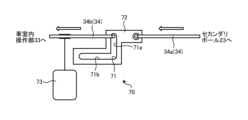
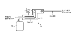
- the in-vehicle operation unit 33 is provided behind the driver's seat so that it cannot be operated while the vehicle is moving, but it is also possible to interpose a transmission switching unit 70 operated by an actuator in the middle of the emergency cable 34, as in the modified example shown in Fig. 19. That is, in the modified example shown in Fig.
- a plate 72 having a crank groove 71 is interposed in the middle of the emergency cable 34, and the end of the part of the emergency cable 34 that leads to the secondary pole 23 (hereinafter referred to as the driven side cable 34a) is connected to the plate 72, while the end of the part of the emergency cable 34 that leads to the in-vehicle operation unit 33 (hereinafter referred to as the drive side cable 34b) is connected so as to be movable inside the crank groove 71.
- the crank groove 71 has a power transmission groove portion 71a that extends in a direction perpendicular to the emergency cable 34, and a non-power transmission groove portion 71b that extends from the power transmission groove portion 71a along the emergency cable 34.
- a shift actuator 73 for changing the position of the end portion relative to the crank groove 71 is connected to the drive side cable 34b.
- the controller 100 when the vehicle is stopped, the controller 100 operates the shift actuator 73, and as shown in FIG. 19A, the end of the drive cable 34b is placed in the power transmission groove 71a of the crank groove 71. Therefore, when the interior operation unit 33 is operated from this state, the driven cable 34a is operated via the plate 72, and the secondary pole 23 rotates in a direction that releases the engagement with the latch 21.
- the vehicle speed is detected by a vehicle speed sensor, but it is also possible to detect the transmission gear position in addition to the vehicle speed, and determine that the vehicle is in a driving state if the transmission is not in the parking position even if the vehicle speed is zero. This makes it possible to prevent the front hood from accidentally opening when the vehicle is stopped at a traffic light, for example.
- the secondary pole 23 when the electric motor 41 operates in the open direction, the secondary pole 23 operates in the release direction, and the primary pole 22 operates in the release direction via the link lever 26 provided between the secondary pole 23 and the primary pole 22; however, it is not necessary to operate the primary pole 22 in the release direction via the secondary pole 22 and the link lever 26.
- the secondary pole it is also possible to configure the secondary pole to operate in the release direction until the operating angle of the actuator unit in the open direction reaches a predetermined threshold, and to operate the primary pole in the release direction when the operating angle in the open direction exceeds the threshold.
- the primary pole is linked when the secondary pole moves in the release direction, but the secondary pole may also be linked when the primary pole moves in the release direction.
- Front hood latch device 10. Housing member, 11. Base plate (housing member), 11a. Surface, 12. Case (housing member), 12a. Inner surface, 12b. Outer surface, 12c. Guide rib, 13. Striker entry groove, 14. Cover (housing member), 21. Latch, 21a. Latch shaft, 21b. Striker contact portion, 21c. Hook portion, 21d. Storage groove, 21e. Latch spring, 21f. Latch pin, 21g. Latch detection magnet, 21h. Case facing surface, 21j. Primary engagement portion, 21k. Secondary engagement portion, 22.
Landscapes
- Engineering & Computer Science (AREA)
- Chemical & Material Sciences (AREA)
- Combustion & Propulsion (AREA)
- Transportation (AREA)
- Mechanical Engineering (AREA)
- Lock And Its Accessories (AREA)
Priority Applications (2)
| Application Number | Priority Date | Filing Date | Title |
|---|---|---|---|
| CN202380096530.8A CN120898053A (zh) | 2023-03-30 | 2023-09-08 | 前发动机罩用闩装置 |
| JP2025509666A JPWO2024202111A1 (https=) | 2023-03-30 | 2023-09-08 |
Applications Claiming Priority (4)
| Application Number | Priority Date | Filing Date | Title |
|---|---|---|---|
| JP2023055514 | 2023-03-30 | ||
| JP2023-055514 | 2023-03-30 | ||
| JP2023-055515 | 2023-03-30 | ||
| JP2023055515 | 2023-03-30 |
Publications (1)
| Publication Number | Publication Date |
|---|---|
| WO2024202111A1 true WO2024202111A1 (ja) | 2024-10-03 |
Family
ID=92903703
Family Applications (1)
| Application Number | Title | Priority Date | Filing Date |
|---|---|---|---|
| PCT/JP2023/032815 Ceased WO2024202111A1 (ja) | 2023-03-30 | 2023-09-08 | フロントフード用ラッチ装置 |
Country Status (3)
| Country | Link |
|---|---|
| JP (1) | JPWO2024202111A1 (https=) |
| CN (1) | CN120898053A (https=) |
| WO (1) | WO2024202111A1 (https=) |
Citations (3)
| Publication number | Priority date | Publication date | Assignee | Title |
|---|---|---|---|---|
| JPS6271253U (https=) * | 1985-10-23 | 1987-05-07 | ||
| JP2016539268A (ja) * | 2013-11-22 | 2016-12-15 | ゲコム コーポレーション | 車両のボンネットラッチ |
| US20180073283A1 (en) * | 2016-09-13 | 2018-03-15 | Hyundai Motor Company | Apparatus for hood latch of vehicle |
-
2023
- 2023-09-08 JP JP2025509666A patent/JPWO2024202111A1/ja active Pending
- 2023-09-08 CN CN202380096530.8A patent/CN120898053A/zh active Pending
- 2023-09-08 WO PCT/JP2023/032815 patent/WO2024202111A1/ja not_active Ceased
Patent Citations (3)
| Publication number | Priority date | Publication date | Assignee | Title |
|---|---|---|---|---|
| JPS6271253U (https=) * | 1985-10-23 | 1987-05-07 | ||
| JP2016539268A (ja) * | 2013-11-22 | 2016-12-15 | ゲコム コーポレーション | 車両のボンネットラッチ |
| US20180073283A1 (en) * | 2016-09-13 | 2018-03-15 | Hyundai Motor Company | Apparatus for hood latch of vehicle |
Also Published As
| Publication number | Publication date |
|---|---|
| JPWO2024202111A1 (https=) | 2024-10-03 |
| CN120898053A (zh) | 2025-11-04 |
Similar Documents
| Publication | Publication Date | Title |
|---|---|---|
| CN110439396B (zh) | 闩锁组件 | |
| US11732514B2 (en) | Closure latch assembly with a power release mechanism and an inside handle release mechanism | |
| JP4473919B2 (ja) | 自動車用ドアラッチ装置 | |
| US10125524B2 (en) | Vehicle door latch control device | |
| US20180371805A1 (en) | Automobile door lock device | |
| US9689182B2 (en) | Vehicle door latch controller | |
| JP6992263B2 (ja) | 車両用開閉体制御装置 | |
| US7441816B2 (en) | Automotive childproof safety lock control apparatus | |
| CN107867155B (zh) | 用于车辆的开闭体控制设备 | |
| JP4389897B2 (ja) | 自動車用ドアの開動作規制装置 | |
| JP2017043894A (ja) | 車両用の蓋体開閉装置 | |
| CN116547160A (zh) | 燃料加注口盖开启器 | |
| JP7363612B2 (ja) | 車両用ドア制御装置 | |
| WO2024202111A1 (ja) | フロントフード用ラッチ装置 | |
| KR20140096188A (ko) | 자동차용 도어 개폐장치 | |
| JP2008101337A (ja) | ラッチ装置 | |
| JP4382473B2 (ja) | 自動車用ドアラッチのラッチ解除装置 | |
| JP2006265982A (ja) | 車両用自動開閉装置 | |
| JP6056314B2 (ja) | 車両のエネルギ供給口装置 | |
| US20250290354A1 (en) | Latch device for front hood | |
| US20250178674A1 (en) | Latch device for front hood | |
| JP3799206B2 (ja) | 車両用ロックのオープン及びクローズ装置 | |
| JP4468745B2 (ja) | ドアロックシステム | |
| CN223794018U (zh) | 前行李箱系统 | |
| JP4079110B2 (ja) | ドアロック駆動装置 |
Legal Events
| Date | Code | Title | Description |
|---|---|---|---|
| 121 | Ep: the epo has been informed by wipo that ep was designated in this application |
Ref document number: 23930743 Country of ref document: EP Kind code of ref document: A1 |
|
| WWE | Wipo information: entry into national phase |
Ref document number: 2025509666 Country of ref document: JP |
|
| WWE | Wipo information: entry into national phase |
Ref document number: CN2023800965308 Country of ref document: CN Ref document number: 202380096530.8 Country of ref document: CN |
|
| NENP | Non-entry into the national phase |
Ref country code: DE |
|
| WWP | Wipo information: published in national office |
Ref document number: 202380096530.8 Country of ref document: CN |
|
| 122 | Ep: pct application non-entry in european phase |
Ref document number: 23930743 Country of ref document: EP Kind code of ref document: A1 |