WO2024201890A1 - 車両冷却構造 - Google Patents
車両冷却構造 Download PDFInfo
- Publication number
- WO2024201890A1 WO2024201890A1 PCT/JP2023/013162 JP2023013162W WO2024201890A1 WO 2024201890 A1 WO2024201890 A1 WO 2024201890A1 JP 2023013162 W JP2023013162 W JP 2023013162W WO 2024201890 A1 WO2024201890 A1 WO 2024201890A1
- Authority
- WO
- WIPO (PCT)
- Prior art keywords
- heat exchanger
- opening
- vehicle
- cooling air
- surface portion
- Prior art date
- Legal status (The legal status is an assumption and is not a legal conclusion. Google has not performed a legal analysis and makes no representation as to the accuracy of the status listed.)
- Ceased
Links
Images



Classifications
-
- B—PERFORMING OPERATIONS; TRANSPORTING
- B60—VEHICLES IN GENERAL
- B60K—ARRANGEMENT OR MOUNTING OF PROPULSION UNITS OR OF TRANSMISSIONS IN VEHICLES; ARRANGEMENT OR MOUNTING OF PLURAL DIVERSE PRIME-MOVERS IN VEHICLES; AUXILIARY DRIVES FOR VEHICLES; INSTRUMENTATION OR DASHBOARDS FOR VEHICLES; ARRANGEMENTS IN CONNECTION WITH COOLING, AIR INTAKE, GAS EXHAUST OR FUEL SUPPLY OF PROPULSION UNITS IN VEHICLES
- B60K11/00—Arrangement in connection with cooling of propulsion units
- B60K11/02—Arrangement in connection with cooling of propulsion units with liquid cooling
- B60K11/04—Arrangement or mounting of radiators, radiator shutters, or radiator blinds
-
- B—PERFORMING OPERATIONS; TRANSPORTING
- B62—LAND VEHICLES FOR TRAVELLING OTHERWISE THAN ON RAILS
- B62D—MOTOR VEHICLES; TRAILERS
- B62D25/00—Superstructure or monocoque structure sub-units; Parts or details thereof not otherwise provided for
- B62D25/08—Front or rear portions
Definitions
- This case concerns a vehicle cooling structure that introduces wind from the front of the vehicle into a heat exchange mechanism for cooling.
- Patent Document 1 proposes a structure in which the flow paths of the cooling air to each heat exchange mechanism are partitioned in a vehicle equipped with multiple heat exchange mechanisms.
- the heat exchange mechanism is provided to extend over the entire area of each flow path that intersects with the flow direction of the cooling air, and all of the cooling air flowing through each flow path is introduced into the heat exchange mechanism.
- the vehicle cooling structure of this case was devised in consideration of these issues, and one of its objectives is to improve the cooling performance of the heat exchange mechanism. However, this objective is not the only objective. Another objective of this case is to achieve effects that cannot be obtained with conventional technology, which are derived from the various components shown in the "Mode for carrying out the invention" described below.
- the disclosed vehicle cooling structure can be realized as the embodiments (application examples) disclosed below, which solve at least part of the above problems.
- Each embodiment from embodiment 2 onwards is an embodiment that can be selected additionally as appropriate, and each embodiment can be omitted. None of the embodiments from embodiment 2 onwards discloses an embodiment or configuration that is essential to the present case.
- the disclosed vehicle cooling structure includes a first heat exchanger, a second heat exchanger that is disposed rearward of the first heat exchanger and includes an area that at least extends downward from the first heat exchanger in a front view, a heat exchange mechanism that exchanges thermal energy with air introduced from the front, an opening through which at least air toward the first heat exchanger flows in from the front, and a protruding fin that forms the lower end of a lower sub-flow passage that flows toward the second heat exchanger below the first heat exchanger and that protrudes toward the second heat exchanger among the flow passages through which the air that flows in from the opening flows, and an introduction member that is attached in front of the second heat exchanger.
- the introduction member is provided such that the opening is located above the protruding fin, and the upper surface of the protruding fin is provided in a shape that slopes downward toward the rear or in a horizontal shape that follows the front-to-rear direction.
- the introduction member is provided below the opening and has a lower opening below the flow path through which air flows in from the front toward the second heat exchanger, and the rear ends of the protruding fins are preferably provided at a position with a gap from the second heat exchanger and are located at the same front-to-rear position as the rear end of the first heat exchanger or further rearward than the rear end.
- the protruding fins extend across the entire area of the first heat exchanger in the vehicle width direction.
- the introduction member has an upper surface portion that is attached to an edge portion of a front end and an upper end of the second heat exchanger and forms an upper end of an upper sub-flow path of the flow path that avoids the first heat exchanger above and heads toward the second heat exchanger.
- the upper surface of the introduction member has a front portion located above the first heat exchanger and a slope portion formed continuously from the front portion to the rear, and is provided in a shape that slopes downward from the edge of the second heat exchanger to the front, and it is preferable that the slope portion has a greater slope in the front-to-rear direction than the front portion.
- the disclosed vehicle cooling structure can improve the cooling performance through the heat exchange mechanism.
- FIG. 2 is an exploded perspective view illustrating a basic configuration of the vehicle cooling structure.
- 2 is a vertical cross-sectional view showing the center in the vehicle width direction of the vehicle cooling structure.
- FIG. 3 is an enlarged cross-sectional view of a main part of FIG. 2 .
- 3 is an enlarged cross-sectional view showing an example in which a bumper part other than the bumper part in FIG. 2 is applied.
- FIG. 2 is a perspective cross-sectional view showing an outer side in a vehicle width direction in the vehicle cooling structure.
- the forward direction of the vehicle is referred to as the front of the vehicle (simply referred to as "forward"), and the backward direction is referred to as the rear of the vehicle (simply referred to as “rear”), with left and right defined based on the forward direction.
- the left and right direction can also be referred to as the width direction of the vehicle or the side.
- the fore-aft direction of the vehicle is simply referred to as the "fore-aft direction.”
- the up-down direction is defined as the direction of gravity being downward and its opposite being upward. Note that the up-down direction does not have to perfectly coincide with the vertical direction, and may be slightly inclined relative to the vertical direction. Similarly, the fore-aft direction and left-right direction do not have to perfectly coincide with the horizontal direction.
- Vehicle structures are often formed with near bilateral symmetry (mirror symmetry with respect to a plane including the yaw axis and roll axis passing through the center of gravity of the vehicle), but a completely symmetrical shape is not necessary.
- the type of vehicle to which the vehicle cooling structure according to the embodiment is applied is not particularly limited, and the vehicle may be applied to, for example, a gasoline vehicle, an electric vehicle (EV), a hybrid vehicle (Hybrid Electric Vehicle, HEV, Hybrid Electric Vehicle), a plug-in hybrid vehicle (Plug-in Hybrid Electric Vehicle, PHEV, Plug-in Hybrid Electric Vehicle), etc.
- a plug-in hybrid vehicle is a hybrid vehicle in which the battery can be charged externally or power can be supplied externally from the battery.
- a plug-in hybrid vehicle is provided with a charging port (inlet) for inserting a charging cable that supplies power from an external charging facility, and an outlet (outlet) for external power supply.
- Fig. 1 is an exploded perspective view showing the configuration of the vehicle cooling structure 1.
- Fig. 2 is a longitudinal cross-sectional view along the front-rear and up-down directions at the center in the vehicle width direction of the vehicle cooling structure 1.
- the vehicle cooling structure 1 is a structure that converts wind taken in when the vehicle is traveling forward into cooling wind (wind), and guides this cooling wind from a front bumper 2 (bumper component) to a heat exchanger 3 (heat exchange mechanism).
- the front bumper 2 is disposed at the very front of the vehicle.
- the front bumper 2 is provided with a lower ventilation section 2L (first ventilation section) penetrating from the front to the rear at the lower part, and an upper ventilation section 2U (second ventilation section) penetrating from the front to the rear at the upper part. Cooling air is taken in from each of the ventilation sections 2L, 2U, and the cooling air thus introduced is guided to the heat exchanger 3.
- the heat exchanger 3 is an in-vehicle device of the cooling system that exchanges thermal energy with cooling air introduced from the front.
- the heat exchanger 3 is exemplified as having an oil cooler 4 (first heat exchanger), a condenser 5 (second heat exchanger), and a radiator 6 (second heat exchanger).
- the oil cooler 4 and the condenser 5 are attached to the radiator 6, and the radiator 6 is attached to the vehicle body (not shown).
- the oil cooler 4 cools oils such as lubricating oil and hydraulic oil used in the vehicle.
- the condenser 5 cools refrigerant used in the vehicle's air conditioning system and battery cooling circuit, and condenses the refrigerant.
- the radiator 6 cools the engine coolant (not shown).
- the heat exchanger 3 may be changed depending on the type of vehicle (on-board equipment), and the object cooled by the heat exchanger 3 may also be changed as appropriate.
- the heat exchanger 3 illustrated in this embodiment is arranged in the following order from front to rear: oil cooler 4, condenser 5, radiator 6.
- the oil cooler 4, condenser 5, and radiator 6 have different extension areas when viewed from front to rear (i.e., as viewed from the front), with the extension area being larger as viewed from the front as they are positioned further rearward.
- the condenser 5 and radiator 6 are provided including areas that extend downward and upward from the oil cooler 4 as viewed from the front
- the radiator 6 is provided including an area that extends downward from the condenser 5 as viewed from the front.
- the oil cooler 4 is arranged to cover the upper portions of the condenser 5 and radiator 6 from the front.
- the vehicle cooling structure 1 of this embodiment is formed with a lower flow path 7 through which the cooling air taken in from the lower ventilation section 2L flows, and an upper flow path 8 through which the cooling air taken in from the upper ventilation section 2U flows, as cooling air flow paths.
- the lower flow path 7 and the upper flow path 8 are structurally partitioned and do not communicate with each other on the upstream side, but communicate with each other on the downstream side.
- upstream and downstream here refer to upstream and downstream in the flow direction of the air taken in from the front of the vehicle. The same applies in the following explanation.
- an upstream lower flow path 71 through which cooling air flows back and forth below the bumper beam 50 is provided upstream of the lower flow path 7, and an upstream upper flow path 81 through which cooling air flows back and forth above the bumper beam 50 is provided upstream of the upper flow path 8.
- a downstream lower flow path 72 is provided downstream of the upstream lower flow path 71 (downstream side of the lower flow path 7), and a downstream upper flow path 82 is provided downstream of the upstream upper flow path 81 (downstream side of the upper flow path 8).
- the upstream lower flow passage 71 and the upstream upper flow passage 81 are arranged side by side vertically to avoid the bumper beam 50, and the downstream lower flow passage 72 and the downstream upper flow passage 82 are arranged to merge behind the bumper beam 50.
- the bumper beam 50 is a structural member that extends in the vehicle width direction at the front end of the vehicle and connects between a pair of left and right side members (not shown) that extend in the fore-and-aft direction.
- the vehicle cooling structure 1 is provided with three members that form the above-mentioned flow paths 7, 8: a first member 10, a second member 20, and a third member 30 (introduction member).
- a first member 10 is shown hatched with thin diagonal lines from the upper left to the lower right
- the second member 20 is shown hatched with thin diagonal lines from the upper right to the lower left
- the third member 30 is shown hatched with thick diagonal lines from the upper left to the lower right.
- the front bumper 2 is shown hatched with thick diagonal lines from the upper right to the lower left
- the sealing materials 9L and 9U described below are shown hatched with intersecting thin diagonal lines.
- the first member 10, the second member 20, and the third member 30 form a duct-like portion (a so-called full duct) that introduces cooling air to the heat exchanger 3 across the entire width of the heat exchanger 3, and is provided behind the front bumper 2.
- the third member 30 is disposed in contact with the rear of the first member 10 and the second member 20.
- the bumper beam 50 is disposed horizontally between the first member 10 and the second member 20.
- the first member 10 is disposed below the bumper beam 50
- the second member 20 is disposed above the bumper beam 50.
- the third member 30 is disposed such that its lower portion is located behind the first member 10, and its upper portion is located behind the second member 20.
- the first member 10 and the second member 20 are provided separately above and below in front of the third member 30.
- the first member 10 is a member that includes a portion that forms the upstream lower flow passage 71.
- the second member 20 is a member that includes a portion that forms the upstream upper flow passage 81.
- the third member 30 is a member that includes a portion that forms the downstream lower flow passage 72 and the downstream upper flow passage 82. To summarize these three members 10, 20, 30, the first member 10 is disposed on the front and lower side, the second member 20 is disposed on the front and upper side, and the third member 30 is disposed on the rear upper and lower side.
- the first member 10 in this embodiment is a duct-shaped member that is fixed to the lower part of the rear surface of the front bumper 2 and defines only the upstream lower flow passage 71 of the flow passages 7, 8. Therefore, in the following description, the "first member 10" will be referred to as the "lower duct 10.”
- the lower duct 10 is a member that is attached to the front bumper 2 (so-called assembled). In other words, the configuration of the lower duct 10 is set according to the configuration of the front bumper 2, and a lower duct 10 specific to the front bumper 2 is used. For example, when front bumpers 2 of different shapes are used depending on the vehicle model or specifications, a lower duct 10 that corresponds to the shape of each front bumper 2 is used.
- the second member 20 in this embodiment is a bracket that attaches the front bumper 2 to the vehicle body.
- the front bumper 2 is attached to the second member 20 with fasteners such as bolts.
- the upper part of the rear surface of the front bumper 2 is fixed to the second member 20, and the second member 20 is attached in front of the radiator 6.
- the “second member 20" is referred to as the "center bracket 20.”
- Some conventional vehicles are equipped with a bracket (center bracket) that attaches the front bumper to the vehicle body.
- conventional center brackets do not have a flow path for air flow, such as the upstream upper flow path 81 described above.
- the center bracket 20 can be said to be a member in which a portion that forms the upstream upper flow path 81 has been added to the conventional center bracket.
- This center bracket 20 is configured according to the front bumper 2.
- the third member 30 in this embodiment has a box-like outer shape. Therefore, in the following description, the "third member 30" will be referred to as the "box 30".
- the box 30 is attached in front of the radiator 6. That is, the configuration of the box 30 is set according to the configuration of the radiator 6, and a box 30 specific to the radiator 6 is used. For example, when radiators 6 of different shapes are used depending on the grade or specifications of the vehicle model, a box 30 corresponding to the shape of each radiator 6 is used.
- the box 30 is fixed with bolts to a rib-shaped portion of the radiator 6 that extends in the vehicle width direction.
- the lower duct 10, center bracket 20, and box 30 are assembled in the following example procedure. First, the box 30 is attached to the radiator 6. Next, the lower duct 10 is attached to the front bumper 2. Alternatively, a front bumper 2 with a lower duct 10 attached is prepared. Then, the front bumper 2 with the lower duct 10 is attached to the center bracket 20 fixed to the vehicle body.
- the box 30 When assembled in the above-mentioned procedure, the box 30 is positioned in contact with the rear of the lower duct 10 and center bracket 20. If the lower duct 10, center bracket 20, and box 30 were fixed with bolts, it would be difficult to assemble in the above-mentioned procedure. Therefore, although the lower duct 10, center bracket 20, and box 30 are positioned in contact with each other as described above, they are not fixed to each other.
- the box 30 is abutted between the lower duct 10 and the center bracket 20 via seal materials 9L, 9U.
- the lower seal material 9L is interposed in a slightly compressed state between the lower part of the box 30 and the lower duct 10
- the upper seal material 9U is interposed in a slightly compressed state between the upper part of the box 30 and the center bracket 20.
- the seal materials 9L, 9U can be sponges attached to the box 30 with double-sided tape.
- the locations where the sealing materials 9L, 9U are installed are preset at common positions regardless of the vehicle model or specifications.
- the area that connects the upstream lower flow path 71 to the downstream lower flow path 72 and the area that connects the upstream upper flow path 81 to the downstream upper flow path 82 are not set in areas that depend on the vehicle model or specifications, but are preset in common areas.
- the lower duct 10, center bracket 20, and box 30 are each described in detail below.
- the lower duct 10 is provided with an upstream lower opening 11 (first opening) into which the cooling air taken in from the lower ventilation portion 2L of the front bumper 2 flows in.
- the upstream lower opening 11 is a cylindrical portion that defines the upstream lower flow passage 71.
- This upstream lower opening 11 is provided in communication with the lower ventilation portion 2L of the front bumper 2, since the cooling air taken in from the lower ventilation portion 2L flows in through this upstream lower opening 11.
- the upstream lower opening 11 is tapered so that the cross section of the flow passage narrows as it moves from the front to the rear of the vehicle.
- the opening that introduces the cooling air from the front to the upstream lower flow passage 71 is larger than the opening that guides the cooling air from the upstream lower flow passage 71 to the rear.
- the upper surface 12 of the upstream lower opening 11 will be described.
- the upper surface 12 is a planar portion that defines the upper portion of the upstream lower flow passage 71 above the upstream lower opening 11.
- This upper surface 12 is provided with a shape that slopes downward toward the rear.
- the upper surface 12 is disposed in a posture that slopes downward toward the rear.
- Expressions based on the front-to-rear direction, such as a "shape that slopes downward toward the rear" and a "posture that slopes downward toward the rear,” can be rephrased as a forward-sloping shape that is positioned lower from the front to the rear, when the up-down direction is used as the reference.
- FIG. 5 is an enlarged perspective cross-sectional view showing a main portion of the lower duct 10 on the vehicle width outer side (left side in Figure 5) in the vehicle cooling structure 1.
- the side walls 13 are erected on the left and right sides of the upstream lower opening 11 on the vehicle width outer side, and are portions that partition the sides of the upstream lower flow path 71.
- the side walls 13 are tapered, narrowing toward the inside in the vehicle width direction as they extend rearward. In other words, the pair of left and right side walls 13 are arranged so that the distance between them in the vehicle width direction becomes smaller as they extend rearward.
- the area outside the side wall 13 in the vehicle width direction is a different area from the upstream lower flow passage 71.
- a fixing portion 14 for attaching the lower duct 10 to the front bumper 2 is set.
- the fixing portion 14 is a portion of the lower duct 10 outside the side wall 13 in the vehicle width direction, and is a portion that is fixed to the front bumper 2.
- Figure 5 shows an example of the configuration of the fixing portion 14 where the lower duct 10 is fixed to the front bumper 2 with a screw 15.
- the screw 15 is screwed into the boss 2B of the front bumper 2.
- Figure 5 also shows an example where a positioning guide pin 2P is inserted into a pin hole 16 drilled in a portion of the lower duct 10 that is further outboard in the vehicle width direction than the side wall 13, as a configuration to assist in fixing the lower duct 10.
- the guide pin 2P is a positioning part that protrudes rearward on the rear surface of the front bumper 2.
- the lower duct 10 is guided (i.e., positioned) to a fixed position relative to the front bumper 2. Then, by screwing the screw 15 into the boss 2B, the lower duct 10 is fixed to the front bumper 2.
- the center bracket 20 is provided with an upstream upper opening 21 (second opening) into which the cooling air taken in from the upper ventilation portion 2U of the front bumper 2 flows in.
- the upstream upper opening 21 is a cylindrical portion that defines the upstream upper flow passage 81. This upstream upper opening 21 is provided in communication with the upper ventilation portion 2U of the front bumper 2, since the cooling air taken in from the upper ventilation portion 2U flows in through it.
- the upstream upper opening 21 is tapered so that the cross section of the flow passage narrows from the front to the rear of the vehicle.
- the opening that introduces the cooling air from the front to the upstream upper flow passage 81 is larger than the opening that guides the cooling air from the upstream upper flow passage 81 to the rear.
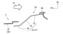
- FIG. 3 is an enlarged cross-sectional view of the lower surface portion 22 and its surroundings in FIG. 2.
- the lower surface portion 22 is a planar portion that defines the lower portion of the upstream upper flow passage 81 below the upstream upper opening 21. This lower surface portion 22 is provided below the upstream upper opening 21 and protrudes forward. Therefore, in the following description, the "lower surface portion 22" will be referred to as the "protruding surface portion 22".
- the protruding surface portion 22 is provided with a shape that is inclined downward toward the front.
- the protruding surface portion 22 is disposed in a forward-sloping position like a chin spoiler.
- Expressions based on the front-to-back direction such as a "shape that is inclined downward toward the front” or a "sloping position toward the front", can be rephrased as a backward-sloping shape that is positioned higher from the front to the rear, if the up-down direction is used as the reference.
- This protruding surface portion 22 has three surfaces 23, 24, and 25 with different degrees of inclination in the front-to-rear direction. Of the three surfaces 23, 24, and 25, the upper surface portion 23 is provided at the rearmost position, the lower surface portion 24 is provided at the frontmost position, and a slope surface portion 25 is provided between the upper surface portion 23 and the lower surface portion 24.
- the upper surface portion 23 and the lower surface portion 24 are both arranged to extend approximately horizontally in the front-to-rear direction. "Approximately horizontal” here does not necessarily mean a completely horizontal shape, but may also include a shape that is slightly inclined downward toward the front.
- the upper surface portion 23 and the lower surface portion 24 may be parallel to each other, or one may be inclined slightly downward toward the front more than the other.
- the slope surface portion 25 is provided with a shape that slopes downward toward the front.
- the upper surface portion 23 is connected to the rear of the slope surface portion 25, and the lower surface portion 24 is connected to the front of the slope surface portion 25. In other words, the upper surface portion 23 and the lower surface portion 24 are less inclined downward toward the front than the slope surface portion 25.
- the protruding surface portion 22 in this embodiment is provided so as to extend below the lower surface portion 2F of the upper ventilation portion 2U.
- at least a front portion of the protruding surface portion 22 is disposed below the lower surface portion 2F of the upper ventilation portion 2U, and overlaps at least a rear portion of the lower surface portion 2F vertically.
- Figure 3 shows an example in which the lower surface portion 24 of the protruding surface portion 22 (at least a front portion of the protruding surface portion 22) overlaps at the top and bottom with a rear portion of the lower surface portion 2F.
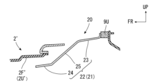
- Figure 4 is an enlarged cross-sectional view showing an embodiment in which a front bumper 2' with a different shape from the front bumper 2 in Figure 3 is used.
- the center bracket 20 in Figure 4 is the same as that in Figure 3.
- the lower surface 2F' of the upper ventilation section 2U' extends rearward and upward beyond the lower surface 2F in FIG. 3.
- at least a front portion of the protruding surface 22 is positioned below the lower surface 2F' of the upper ventilation section 2U' and overlaps at least a rear portion of this lower surface 2F' vertically.
- the rear ends of the lower surfaces 2F, 2F' and the protruding surface portion 22 are spaced apart vertically. This distance is set to a dimension that ensures both the mounting of the front bumpers 2, 2' to the center bracket 20 and the prevention of leakage of cooling air.
- the box 30 is provided with a downstream lower opening 31 (third opening) communicating with the upstream lower opening 11, and a downstream upper opening 32 (fourth opening) communicating with the upstream upper opening 21.
- the downstream lower opening 31 is airtightly connected to the upstream lower opening 11 via a seal material 9L.
- the downstream upper opening 32 is airtightly connected to the upstream upper opening 21 via a seal material 9U.
- airtight here may include not only a completely sealed state, but also a state with a small gap (a nearly sealed state in which almost no air leaks through the gap).
- the box 30 guides the cooling air that flows into the upstream lower opening 11 to the heat exchanger 3 through the downstream lower opening 31, and guides the cooling air that flows into the upstream upper opening 21 to the heat exchanger 3 through the downstream upper opening 32.
- the downstream lower opening 31 is a portion that defines and defines a downstream lower flow passage 72.
- the downstream lower flow passage 72 is a flow passage for cooling air that flows mainly toward the radiator 6 of the heat exchanger 3.
- the cooling air flows into this downstream lower flow passage 72 from the front through a box lower opening 33 (lower opening, shown by a dashed line in FIG. 2 ) that serves as an inlet for the cooling air.
- the cooling air that flows into the box lower opening 33 flows toward the radiator 6.
- the downstream upper opening 32 is a section that defines the downstream upper flow passage 82.
- the downstream upper flow passage 82 is a flow passage for cooling air toward the radiator 6, and the entire oil cooler 4 and the upper half of the condenser 5 are disposed on this flow passage.
- the oil cooler 4 is disposed so as to be surrounded by the downstream upper opening 32, and a box 30 is provided in front of the radiator 6.
- Cooling air flows into the downstream upper flow passage 82 from the box upper opening 34 (opening, shown by a dashed line in FIG. 2) which serves as an inlet for cooling air.
- the cooling air that flows into the box upper opening 34 flows toward at least the oil cooler 4.
- the box lower opening 33 is provided below the box upper opening 34.
- a lower sub-flow passage 8L that avoids the oil cooler 4 downward and an upper sub-flow passage 8U that avoids the oil cooler 4 upward are set as flow passages through which the cooling air flows.
- the cooling air in the lower sub-flow passage 8L and the upper sub-flow passage 8U flows toward the condenser 5 or the radiator 6 after avoiding the oil cooler 4 upward or downward.
- the flow passage below the oil cooler 4 that flows toward the condenser 5 or the radiator 6 is the lower sub-flow passage 8L
- the flow passage above the oil cooler 4 that flows toward the condenser 5 or the radiator 6 is the upper sub-flow passage 8U.
- a downstream portion of the lower sub-channel 8L communicates with the downstream lower channel 72.
- the upstream side of the downstream portion of the lower sub-channel 8L is structurally separated by a protruding fin 40 provided on the box 30.
- FIG. 2 shows an example in which the box upper opening 34 is provided above the protruding fin 40.
- the protruding fin 40 is a fin-shaped portion that protrudes toward the rear (condenser 5 and radiator 6) while being spaced downward from the oil cooler 4, and extends across the entire area of the oil cooler 4 in the vehicle width direction.
- the protruding fin 40 is not only spaced downward from the oil cooler 4, but also spaced forward from the condenser 5 and radiator 6. That is, the rear end 41 of the protruding fin 40 is provided at a position with a gap forward from the condenser 5 and radiator 6. Specifically, the rear end 41 of the protruding fin 40 is located at the same fore-aft position as the rear end 4R of the oil cooler 4, or further rearward than this rear end 4R.
- the gap between the protruding fin 40 and the condenser 5 and radiator 6 in the fore-aft direction corresponds to the area where a downstream portion of the lower sub-flow passage 8L communicates with the downstream lower flow passage 72.
- the upper surface 42 of the protruding fin 40 is provided in a shape that slopes downward toward the rear. However, the upper surface 42 of the protruding fin 40 may also be provided in a horizontal shape along the front-to-rear direction.
- the lower end of the lower sub-channel 8L is defined by the protruding fin 40.
- the protruding fin 40 forms the lower end of the lower sub-channel 8L, thereby defining the lower end of the lower sub-channel 8L.
- the defined area by the protruding fin 40 is the lower end of the region upstream of a portion of the lower sub-channel 8L on the downstream side (i.e., the region that communicates with the downstream lower channel 72).
- the upper end of the upper sub-flow passage 8U is defined over its entire area by the upper surface portion 35 of the box 30.
- the upper end of the upper sub-flow passage 8U is defined by the upper surface portion 35 of the box 30 forming the upper end of the upper sub-flow passage 8U.
- the upper surface portion 35 is attached to the front and upper edge portion 6F of the radiator 6.
- the upper surface portion 35 of the box 30 extends forward like an eave from the edge portion 6F of the radiator 6, and covers the oil cooler 4 and condenser 5 from above.
- This upper surface portion 35 is formed in a shape that slopes downward and forward from the edge portion 6F of the radiator 6.
- the upper surface portion 35 of this embodiment is provided with a front portion 36 located above the oil cooler 4, and a slope portion 37 formed continuously from the front portion 36 to the rear.
- the slope portion 37 is formed so that the inclination in the front-to-rear direction is greater than the inclination in the front-to-rear direction of the front portion 36.
- the dimension by which the front portion 36 is spaced upward from the oil cooler 4 is set to, for example, 20 mm from the viewpoint of simultaneously suppressing excessive inflow of cooling air from the main flow path 8M into the upper sub-flow path 8U and ensuring the flow rate of cooling air flowing into the upper sub-flow path 8U.
- the vehicle cooling structure 1 of the present embodiment has the above-mentioned configuration, it has the following advantages. First, the effects of the vehicle cooling structure 1 including the three components of the lower duct 10, the center bracket 20, and the box 30 will be described in (1A) to (10A). Then, the effects of the vehicle cooling structure 1 including the protruding fins 40 will be described in (1B) to (6B).
- the vehicle cooling structure 1 includes three components for introducing cooling air: a lower duct 10, a center bracket 20, and a box 30.
- An upstream lower opening 11 of the lower duct 10 is provided so as to communicate with a downstream lower opening 31 of the box 30.
- an upstream upper opening 21 of the center bracket 20 is provided so as to communicate with a downstream upper opening 32 of the box 30.
- the lower openings 11, 31 and the upper openings 21, 32 are provided so as to communicate with each other in the front-to-rear direction.
- the cooling air taken in through the ventilation sections 2L, 2U of the front bumper 2 can be guided to the heat exchanger 3 without leakage, improving the cooling performance of the heat exchanger 3. Furthermore, with the above-mentioned structure, the three components of the lower duct 10, center bracket 20, and box 30 can each be made smaller, and the gaps that occur between the components can be reduced. This also allows the cooling air taken in through the ventilation sections 2L, 2U of the front bumper 2 to be guided to the heat exchanger 3 without leakage, improving the cooling performance of the heat exchanger 3.
- the lower flow passage 7 and the upper flow passage 8 are formed by the three components of the lower duct 10, the center bracket 20, and the box 30.
- the lower flow passage 7 is a flow passage through which the cooling air taken in from the lower ventilation section 2L passes through the upstream lower opening 11 and then the downstream lower opening 31 to the radiator 6.
- the upper flow passage 8 is a flow passage through which the cooling air taken in from the upper ventilation section 2U passes through the upstream upper opening 21 and then the downstream upper opening 32 to the heat exchanger 3 including the oil cooler 4.
- the formation of these two flow passages 7 and 8 makes it easier to design the flow rate of the cooling air introduced into each of the oil cooler 4, the condenser 5, and the radiator 6. In other words, it becomes easier to design and adjust the flow rate of the cooling air introduced into each of the upper and lower regions of the heat exchanger 3. This also contributes to improving the cooling performance of the heat exchanger 3.
- the center bracket 20 has a protruding surface 22 that protrudes forward below the upstream upper opening 21. This protruding surface 22 reduces the gap between the center bracket 20 and the front bumper 2. This reduces the leakage of cooling air from the gap, improving the cooling performance of the heat exchanger 3.
- the protruding surface portion 22 is formed in a shape that is inclined downward toward the front. Therefore, the opening of the cooling air flowing into the upstream upper opening 21 (i.e., the cooling air inlet) can be expanded downward. This ensures a sufficient flow rate of the cooling air, improving the cooling performance of the heat exchanger 3. In addition, the cooling air can be smoothly introduced while avoiding interference with surrounding structures such as the bumper beam 50.
- the protruding surface portion 22 is provided with a slope surface portion 25 that is inclined downward toward the front, and an upper surface portion 23 and a lower surface portion 24 that extend approximately horizontally in front of and behind the slope surface portion 25. Therefore, it is possible to attach a common center bracket 20 to a front bumper 2 in which the lower surface portion 2F overlaps only the lower surface portion 24 from above and below as shown in FIG. 3, or to a front bumper 2' in which the lower surface portion 2F' overlaps not only the lower surface portion 24 but also the front half of the slope surface portion 25 from above and below as shown in FIG. 4.
- the lower step surface portion 24 can suppress leakage of cooling air, while the upper step surface portion 23 and the slope surface portion 25 can properly guide the cooling air.
- the cooling air can be appropriately guided by the upper step surface portion 23 while effectively suppressing leakage of the cooling air by not only the lower step surface portion 24 but also the front half of the slope surface portion 25.
- a front portion of the protruding surface portion 22 overlaps vertically with a rear portion of the lower surface portion 2F, 2F'. This makes it possible to prevent cooling air from leaking out from between the lower surface portion 2F, 2F' and the protruding surface portion 22.
- a so-called labyrinth structure is used, which effectively prevents cooling air from leaking out from between the lower surface portion 2F' and the protruding surface portion 22.
- the side walls 13 are tapered and positioned inward in the vehicle width direction as they move rearward, allowing the opening of the cooling air flowing into the upstream lower opening 11 to be expanded to the left and right. This ensures a sufficient flow rate of the cooling air, improving the cooling performance of the heat exchanger 3. In this way, the cooling air that flows into the upstream lower opening 11 can be smoothly guided to the radiator 6 via the downstream lower opening 31, ensuring the cooling performance of the radiator 6.
- the lower duct 10 is fixed to the front bumper 2 at the fixing portion 14 that is on the outer side of the side wall 13 in the vehicle width direction. Therefore, the lower duct 10 can be fixed to the front bumper 2 without impeding the flow of cooling air flowing in from the upstream lower opening 11.
- the upper surface 12 of the upstream lower opening 11 is formed in a shape that slopes downward toward the rear. This allows the opening of the cooling air flowing into the upstream lower opening 11 to be expanded upward. This ensures a sufficient flow rate of the cooling air introduced from the upstream lower opening 11, improving the cooling performance of the radiator 6. In addition, the cooling air can be smoothly introduced while avoiding interference with surrounding structures such as the bumper beam 50.
- the box 30 is in contact with the lower duct 10 and the center bracket 20 via the sealing materials 9L and 9U, so that gaps that could allow cooling air to leak out are blocked by the sealing materials 9L and 9U. This effectively prevents the cooling air from leaking out, further improving the cooling performance of the heat exchanger 3.
- the locations where the sealing materials 9L and 9U are installed are preset to common locations regardless of vehicle model or specifications. Therefore, the joining and fixing locations of the lower duct 10, center bracket 20, and box 30 can be standardized regardless of vehicle model or specifications, making it possible to suppress the degree of cooling air leakage (ensuring so-called full duct performance) for all vehicle models or specifications.
- the lower duct 10, center bracket 20, and box 30 form duct-like parts that introduce cooling air to the heat exchanger 3 over the entire width of the heat exchanger 3, so that the cooling air can be guided over the entire width of the heat exchanger 3. This also improves the cooling performance of the heat exchanger 3.
- the downstream upper passage 82 is partitioned and formed by the downstream upper opening 32 of the box 30.
- the downstream upper passage 82 not only the main passage 8M toward the oil cooler 4 but also a lower sub-passage 8L that avoids the oil cooler 4 downward is provided as a passage through which the cooling air flows.
- the lower end of this lower sub-passage 8L is partitioned by the protruding fin 40 of the box 30.
- the cooling efficiency of the oil cooler 4 can be ensured by the cooling air flowing through the main passage 8M of the downstream upper passage 82, and the cooling efficiency of the condenser 5 or the radiator 6 can be ensured by the cooling air flowing through the lower sub-passage 8L. Therefore, the cooling performance of the heat exchanger 3 can be improved.
- the cooling air would be blocked by the oil cooler, causing a pressure increase in front of the oil cooler, which could reduce the efficiency of introducing the cooling air.
- the cooling performance of a heat exchanger such as the oil cooler could become insufficient.
- the lower sub-flow passage 8L is provided, so that the pressure rise in front of the oil cooler 4 is suppressed and the efficiency of introducing the cooling air can be ensured. This improves the cooling performance of not only the oil cooler 4 but also the condenser 5 or the radiator 6.
- the box upper opening 34 is located higher than the protruding fins 40, and the top surfaces 42 of the protruding fins 40 are inclined downward toward the rear. This allows the cooling air that flows from the box upper opening 34 into the lower sub-flow passage 8L to be smoothly guided downward toward the oil cooler 4. By directing the cooling air toward the condenser 5 or radiator 6 in this manner, it helps to improve the cooling performance of the condenser 5 or radiator 6. This effect can also be achieved if the top surfaces 42 of the protruding fins 40 are in a horizontal shape along the fore-and-aft direction.
- the rear end 41 of the protruding fin 40 is located at the same fore-aft position as the rear end 4R of the oil cooler 4 or further rearward than this rear end 4R.
- the cooling air flowing in from the box upper opening 34 and flowing through the lower sub-flow passage 8L of the downstream upper flow passage 82 is appropriately guided. This makes it possible to suppress interference between the cooling air flowing through the downstream upper flow passage 82 and the cooling air flowing in from the box lower opening 33 and flowing through the downstream lower flow passage 72 (in other words, to straighten the flow).
- the protruding fins 40 extend across the entire width of the oil cooler 4. This allows the cooling air to be guided across the entire width of the oil cooler 4. This improves the cooling performance of the oil cooler 4.
- the downstream upper flow path 82 is provided with an upper sub-flow path 8U that avoids the oil cooler 4 above as a flow path for the cooling air to flow.
- the upper end of this upper sub-flow path 8U is defined by the upper surface portion 35 attached to the front and upper edge portion 6F of the radiator 6.
- the upper sub-flow path 8U defined in this manner can further improve the cooling efficiency of the condenser 5 or the radiator 6.
- the lower sub-flow path 8L and the upper sub-flow path 8U can effectively suppress the pressure increase in front of the oil cooler 4, and can simultaneously improve the cooling performance of the oil cooler 4 and the cooling performance of the condenser 5 or the radiator 6.
- the upper surface portion 35 is provided with a shape that slopes downward from the edge portion 6F of the radiator 6 to the front. Therefore, the flow rate of the cooling air flowing through the upper sub-flow passage 8U can be appropriately narrowed, and a shortage of cooling air to the oil cooler 4 can be avoided.
- This upper surface portion 35 is provided with a front portion 36 located above the oil cooler 4 and a slope portion 37 that is continuously formed from the front portion 36 to the rear. Since the slope portion 37 is formed with a larger inclination than the front portion 36, the opening for the cooling air upstream of the upper sub-flow passage 8U can be secured, and the gap between the front portion 36 of the upper surface portion 35 and the oil cooler 4 can be appropriately set. In other words, it is possible to suppress the excessive inflow of cooling air from the main flow passage 8M to the upper sub-flow passage 8U and to secure the flow rate of the cooling air flowing into the upper sub-flow passage 8U at the same time.
- the vehicle cooling structure described above is merely an example, and is not limited to the above.
- the condenser 5 may be omitted from the heat exchanger 3 .
- a modified example I of the vehicle cooling structure 1 including the three members 10, 20, and 30 will be described.
- a modified example II of the vehicle cooling structure 1 including the protruding fins 40 will be described.
- the lower surface portion of the upstream upper opening (second opening) need only be a portion that defines at least the lower portion of the upstream upper flow passage, and may have a shape and posture different from those described above.
- the side wall and the upper surface of the lower duct (first member) may have any shape or arrangement as long as they are portions that define at least the upstream lower flow passage.
- the fixing portion of the lower duct may also be fixed at any position.
- the sealing material may be omitted.
- the first member is not limited to the above-mentioned lower duct 10, but may be any member having an upstream lower opening (first opening).
- the second member is not limited to the above-mentioned center bracket 20, but may be any member having an upstream upper opening (second opening).
- the third member is not limited to the above-mentioned box 30, but may be any member having a downstream lower opening (third opening) communicating with the upstream lower opening and a downstream upper opening (fourth opening) communicating with the upstream upper opening.
- the vehicle need only be provided with a heat exchanger to which cooling air is guided from the downstream lower opening and the downstream upper opening, and does not necessarily need to be provided with an oil cooler or a condenser.
- the vehicle cooling structure according to the modified example I only needs to include a front bumper having a lower ventilation portion and an upper ventilation portion, and a first member, a second member and a third member, and other configurations are optional.
- the box may have any shape.
- the box does not necessarily have to be provided with the upper sub-channel.
- the box needs to be provided with at least the downstream upper flow passage, and does not need to be provided with the downstream lower flow passage into which cooling air flows from the box lower opening.
- the configurations of the extending area, rear end position, and upper surface shape of the protruding fins are not limited to those described above, and other configurations may be adopted.
- Two types of heat exchangers may be provided: a first heat exchanger provided in the flow path of the cooling air flowing in from the box upper opening, and a second heat exchanger provided behind the first heat exchanger and including an area that extends at least downward from the first heat exchanger in a front view.
- a known heat exchanger may be used for the first heat exchanger instead of or in addition to an oil cooler.
- only one of a condenser and a radiator may be used for the second heat exchanger, or a known heat exchanger may be used instead of or in addition to at least one of the condenser and the radiator.
- the third member is not limited to the above-mentioned box 30, but may be any member as long as it is provided with an opening through which cooling air flows in from the front toward the first heat exchanger and a protruding fin that forms the lower end of the lower sub-flow passage.
- the vehicle cooling structure according to the modified example II needs to include at least the heat exchanger and the third member, and other configurations are optional.
- This invention can be used in the manufacturing industry of vehicles equipped with heat exchangers.
Landscapes
- Engineering & Computer Science (AREA)
- Chemical & Material Sciences (AREA)
- Combustion & Propulsion (AREA)
- Transportation (AREA)
- Mechanical Engineering (AREA)
- Cooling, Air Intake And Gas Exhaust, And Fuel Tank Arrangements In Propulsion Units (AREA)
Abstract
Description
態様5.上記の態様1~4のいずれか一つにおいて、前記導入部材は、前記第二熱交換器における前端かつ上端の縁部に取り付けられるとともに前記流路のうち前記第一熱交換器を上方に避けて前記第二熱交換器へ向かうアッパサブ流路の上端を形成する上面部を有することが好ましい。
[1-1.全体構成]
図1は、車両冷却構造1の構成を分解して示す斜視図である。図2は、車両冷却構造1の車幅方向中央における前後方向かつ上下方向に沿う縦断面図である。車両冷却構造1は、車両の前進走行時に取り入れられた走行風を冷却風(風)とし、この冷却風をフロントバンパ2(バンパー部品)から熱交換器3(熱交換機構)まで案内する構造である。
熱交換器3は、前方から導入された冷却風と熱エネルギーを交換する冷却系の車載機器である。
図1及び図2に示すように、ロアダクト10には、フロントバンパ2のロア通気部2Lから取り入れられた冷却風が流入する上流ロア開口部11(第一開口部)が設けられている。図2に示すように、上流ロア開口部11は、上流ロア流路71を区画して形成する筒状の部位である。この上流ロア開口部11は、ロア通気部2Lから取り入れられた冷却風が流入することから、フロントバンパ2のロア通気部2Lに連通して設けられる。
図2に示すように、センターブラケット20には、フロントバンパ2のアッパ通気部2Uから取り入れられた冷却風が流入する上流アッパ開口部21(第二開口部)が設けられている。上流アッパ開口部21は、上流アッパ流路81を区画して形成する筒状の部位である。この上流アッパ開口部21は、アッパ通気部2Uから取り入れられた冷却風が流入することから、フロントバンパ2のアッパ通気部2Uと連通して設けられる。
図2に示すように、ボックス30には、上流ロア開口部11に連通する下流ロア開口部31(第三開口部)と、上流アッパ開口部21に連通する下流アッパ開口部32(第四開口部)とが設けられている。下流ロア開口部31は、シール材9Lを介して上流ロア開口部11に気密に連通している。下流アッパ開口部32は、シール材9Uを介して上流アッパ開口部21に気密に連通している。なお、ここでいう「気密」とは、完全な密閉状態だけでなく、僅かな隙間があいている状態(風が隙間からほとんど漏れないようなほぼ密閉されている状態)を含んでよい。
下流ロア開口部31は、下流ロア流路72を区画して形成する部位である。下流ロア流路72は、熱交換器3のうち主にラジエータ6へ向かう冷却風の流路である。この下流ロア流路72には、冷却風の導入口をなすボックスロア開口33(ロア開口,図2には一点鎖線で示す)を通じて冷却風が前方から流入する。ボックスロア開口33に流入した冷却風は、ラジエータ6へ向けて流通する。
本実施形態の車両冷却構造1は、上述の構成を備えているため、下記の効果を奏する。
まず、ロアダクト10,センターブラケット20及びボックス30の三部材を備えた車両冷却構造1に係る効果を(1A)~(10A)に記す。その後、突出フィン40を備えた車両冷却構造1に係る効果を(1B)~(6B)に記す。
(1A)車両冷却構造1は、冷却風を導入する部材として、ロアダクト10,センターブラケット20,ボックス30の三つを備えている。ロアダクト10の上流ロア開口部11は、ボックス30の下流ロア開口部31と連通するように設けられる。また、センターブラケット20の上流アッパ開口部21は、ボックス30の下流アッパ開口部32と連通するように設けられる。このように、下方の開口部11,31及び上方の開口部21,32のそれぞれは、前後方向において連通するように設けられている。
図4に示すように下段面部24とスロープ面部25の前半部との上下に下面部2F′がラップするフロントバンパ2′に対しては、下段面部24だけでなくスロープ面部25の前半部によって冷却風の漏れを効果的に抑制しつつ、上段面部23によって冷却風を適切に案内できる。
(1B)車両冷却構造1によれば、ボックス30の下流アッパ開口部32によって下流アッパ流路82が区画形成される。この下流アッパ流路82には、冷却風が流通する流路として、オイルクーラ4へ向かうメイン流路8Mだけでなく、オイルクーラ4を下方に避けるロアサブ流路8Lが設けられている。このロアサブ流路8Lの下端は、ボックス30の突出フィン40によって区画されている。そのため、下流アッパ流路82のうちメイン流路8Mを流通する冷却風によってオイルクーラ4による冷却効率を確保できるとともに、ロアサブ流路8Lを流通する冷却風によってコンデンサ5あるいはラジエータ6による冷却効率を確保できる。よって、熱交換器3による冷却性能を向上できる。
これに対し、上述した車両冷却構造1によれば、ロアサブ流路8Lが設けられることから、オイルクーラ4の前方での圧力上昇が抑制され、冷却風の導入効率を確保できる。これにより、オイルクーラ4だけでなくコンデンサ5あるいはラジエータ6による冷却性能をも高められる。
上述した車両冷却構造は一例であって、上述したものに限られない。
例えば、熱交換器3からコンデンサ5を省略してもよい。
以下、三部材10,20,30を備えた車両冷却構造1に関する変形例Iを記す。その後に、突出フィン40を備えた車両冷却構造1に関する変形例IIを記す。
センターブラケット(第二部材)に関し、上流アッパ開口部(第二開口部)の下面部は、少なくとも上流アッパ流路の下部を区画する部位であればよく、上述の形状や姿勢とは異なっていてもよい。
ロアダクト(第一部材)に関し、側壁や上面部は、少なくとも上流ロア流路を区画する部位であればよく、任意の形状や配置を採用してもよい。ロアダクトの固定部についても、任意の箇所で固定する構成を採用できる。
第一部材は、上記のロアダクト10に限らず、上流ロア開口部(第一開口部)を有する任意の部材であってもよい。第二部材は、上記のセンターブラケット20に限らず、上流アッパ開口部(第二開口部)を有する任意の部材であってもよい。第三部材は、上記のボックス30に限らず、上流ロア開口部に連通する下流ロア開口部(第三開口部)と上流アッパ開口部に連通する下流アッパ開口部(第四開口部)とを有する任意の部材であってもよい。
変形例Iに係る車両冷却構造は、ロア通気部及びアッパ通気部を有するフロントバンパ、並びに、第一部材,第二部材及び第三部材を備えていればよく、他の構成は任意である。
ボックス(導入部材)の形状には、任意の形状を採用できる。また、ボックスにアッパサブ流路が設けられていなくてもよい。
ボックスには、少なくとも下流アッパ流路が設けられていればよく、ボックスロア開口から冷却風が流入する下流ロア流路は設けられていなくてもよい。
突出フィンの延在領域,後端の位置,上面の形状といった各形態は、上述の形態に限らず、他の形態を採用してもよい。
変形例IIに係る車両冷却構造は、少なくとも熱交換器及び第三部材を備えていればよく、他の構成は任意である。
2,2′ フロントバンパ(バンパー部品)
3 熱交換器(熱交換機構)
4 オイルクーラ(第一熱交換器)
5 コンデンサ(第二熱交換器)
6 ラジエータ(第二熱交換器)
6F 縁部
7 ロア流路
8 アッパ流路
8L ロアサブ流路
8U アッパサブ流路
10 ロアダクト(第一部材)
20 センターブラケット(第二部材)
30 ボックス(第三部材,導入部材)
33 ボックスロア開口(ロア開口)
34 ボックスアッパ開口(開口)
35 上面部
36 前部
37 スロープ部
40 突出フィン
Claims (6)
- 第一熱交換器と、前記第一熱交換器に対して後方であって前面視で前記第一熱交換器から少なくとも下方にはみ出す領域を含んで設けられた第二熱交換器とを有し、前方から導入された風と熱エネルギーを交換する熱交換機構と、
少なくとも前記第一熱交換器へ向かう風が前方から流入する開口と、前記開口から流入した風が流通する流路のうち前記第一熱交換器の下方において前記第二熱交換器へ向かうロアサブ流路の下端を形成するとともに前記第二熱交換器へ向けて突設される突出フィンとを有し、前記第二熱交換器の前方に取り付けられる導入部材と、を備えた
ことを特徴とする、車両冷却構造。 - 前記導入部材は、前記突出フィンよりも前記開口のほうが上方に設けられ、前記突出フィンの上面が後方へ下方傾斜した形状又は前後方向に沿う水平の形状に設けられる
ことを特徴とする、請求項1記載の車両冷却構造。 - 前記導入部材は、前記開口の下方に設けられるとともに前記流路よりも下方において前記第二熱交換器へ向かう風が前方から流入するロア開口を有し、
前記突出フィンの後端は、前記第二熱交換器に対して隙間をあけた位置に設けられ、且つ、前記第一熱交換器の後端と同じ前後方向位置又は前記後端よりも後方に配置される
ことを特徴とする、請求項1又は2記載の車両冷却構造。 - 前記突出フィンは、前記第一熱交換器の車幅方向全域に亘って延在する
ことを特徴とする、請求項1~3のいずれか一項に記載の車両冷却構造。 - 前記導入部材は、前記第二熱交換器における前端かつ上端の縁部に取り付けられるとともに前記流路のうち前記第一熱交換器を上方に避けて前記第二熱交換器へ向かうアッパサブ流路の上端を形成する上面部を有する
ことを特徴とする、請求項1~4のいずれか一項に記載の車両冷却構造。 - 前記導入部材の前記上面部は、前記第一熱交換器に対して上方に位置する前部と、前記前部から後方へ連続形成されたスロープ部とを有し、前記第二熱交換器の前記縁部から前方へ下方傾斜した形状に設けられ、前後方向に対する傾斜が前記前部よりも前記スロープ部のほうが大きい
ことを特徴とする、請求項5記載の車両冷却構造。
Priority Applications (2)
| Application Number | Priority Date | Filing Date | Title |
|---|---|---|---|
| PCT/JP2023/013162 WO2024201890A1 (ja) | 2023-03-30 | 2023-03-30 | 車両冷却構造 |
| JP2025509493A JPWO2024201890A1 (ja) | 2023-03-30 | 2023-03-30 |
Applications Claiming Priority (1)
| Application Number | Priority Date | Filing Date | Title |
|---|---|---|---|
| PCT/JP2023/013162 WO2024201890A1 (ja) | 2023-03-30 | 2023-03-30 | 車両冷却構造 |
Publications (1)
| Publication Number | Publication Date |
|---|---|
| WO2024201890A1 true WO2024201890A1 (ja) | 2024-10-03 |
Family
ID=92904393
Family Applications (1)
| Application Number | Title | Priority Date | Filing Date |
|---|---|---|---|
| PCT/JP2023/013162 Ceased WO2024201890A1 (ja) | 2023-03-30 | 2023-03-30 | 車両冷却構造 |
Country Status (2)
| Country | Link |
|---|---|
| JP (1) | JPWO2024201890A1 (ja) |
| WO (1) | WO2024201890A1 (ja) |
Citations (6)
| Publication number | Priority date | Publication date | Assignee | Title |
|---|---|---|---|---|
| JPH05202748A (ja) * | 1992-01-29 | 1993-08-10 | Nippondenso Co Ltd | 車両用水冷式内燃機関の冷却装置 |
| JPH08132894A (ja) * | 1994-11-02 | 1996-05-28 | Suzuki Motor Corp | 車両エンジンの冷却装置 |
| JP2017514744A (ja) * | 2014-04-30 | 2017-06-08 | ヴァレオ システム テルミク | エアガイド及びエアガイドモジュール |
| JP2017105392A (ja) * | 2015-12-11 | 2017-06-15 | カルソニックカンセイ株式会社 | 冷却装置 |
| JP2018118591A (ja) * | 2017-01-24 | 2018-08-02 | 三菱自動車工業株式会社 | 車両構造 |
| JP2019131106A (ja) * | 2018-02-01 | 2019-08-08 | いすゞ自動車株式会社 | 車両の前部構造 |
-
2023
- 2023-03-30 WO PCT/JP2023/013162 patent/WO2024201890A1/ja not_active Ceased
- 2023-03-30 JP JP2025509493A patent/JPWO2024201890A1/ja active Pending
Patent Citations (6)
| Publication number | Priority date | Publication date | Assignee | Title |
|---|---|---|---|---|
| JPH05202748A (ja) * | 1992-01-29 | 1993-08-10 | Nippondenso Co Ltd | 車両用水冷式内燃機関の冷却装置 |
| JPH08132894A (ja) * | 1994-11-02 | 1996-05-28 | Suzuki Motor Corp | 車両エンジンの冷却装置 |
| JP2017514744A (ja) * | 2014-04-30 | 2017-06-08 | ヴァレオ システム テルミク | エアガイド及びエアガイドモジュール |
| JP2017105392A (ja) * | 2015-12-11 | 2017-06-15 | カルソニックカンセイ株式会社 | 冷却装置 |
| JP2018118591A (ja) * | 2017-01-24 | 2018-08-02 | 三菱自動車工業株式会社 | 車両構造 |
| JP2019131106A (ja) * | 2018-02-01 | 2019-08-08 | いすゞ自動車株式会社 | 車両の前部構造 |
Also Published As
| Publication number | Publication date |
|---|---|
| JPWO2024201890A1 (ja) | 2024-10-03 |
Similar Documents
| Publication | Publication Date | Title |
|---|---|---|
| US11890923B2 (en) | Upper body heat exchanger for vehicles | |
| US9061585B2 (en) | Cooling air introduction apparatus for vehicle | |
| US9669729B2 (en) | Mobile body equipped with fuel cell | |
| JP6509277B2 (ja) | 車両用熱交換装置 | |
| JP6064730B2 (ja) | 冷却装置 | |
| US20090266508A1 (en) | Cooling apparatus for a fuel cell powered vehicle | |
| US11981195B2 (en) | Duct surface heat exchanger for vehicles | |
| JP6526741B2 (ja) | 車両の吸気構造 | |
| JP2011006051A (ja) | 車両のバッテリアセンブリ冷却構造、および、ウォータージャケット付きバッテリアセンブリ | |
| JP2019081509A (ja) | 車両の冷却構造 | |
| JP2024172115A (ja) | 車両駆動装置 | |
| WO2024201890A1 (ja) | 車両冷却構造 | |
| WO2024201889A1 (ja) | 車両冷却構造 | |
| JP2018103840A (ja) | 車体構造 | |
| JP7446561B2 (ja) | 車両用ラジエータ | |
| JP2015128923A (ja) | 車両用冷却装置 | |
| US20170106740A1 (en) | Heat exchanger for vehicle and heat exchanging system having the same | |
| WO2025032784A1 (ja) | 車両前部構造 | |
| CN102802991B (zh) | 冷却设备和包括冷却设备的车辆 | |
| JP7339901B2 (ja) | 車両のバッテリ搭載構造及びバッテリの搭載方法 | |
| JP2026028493A (ja) | 熱交換装置 | |
| CN115366659B (zh) | 车辆用热交换装置 | |
| JP2021027010A (ja) | 車両用バッテリパック | |
| JP2019069645A (ja) | 車両 | |
| JP2006248333A (ja) | 車両用のクーリングシステム |
Legal Events
| Date | Code | Title | Description |
|---|---|---|---|
| 121 | Ep: the epo has been informed by wipo that ep was designated in this application |
Ref document number: 23930528 Country of ref document: EP Kind code of ref document: A1 |
|
| ENP | Entry into the national phase |
Ref document number: 2025509493 Country of ref document: JP Kind code of ref document: A |
|
| WWE | Wipo information: entry into national phase |
Ref document number: 2025509493 Country of ref document: JP |
|
| WWE | Wipo information: entry into national phase |
Ref document number: 2501006421 Country of ref document: TH |
|
| NENP | Non-entry into the national phase |
Ref country code: DE |
|
| 122 | Ep: pct application non-entry in european phase |
Ref document number: 23930528 Country of ref document: EP Kind code of ref document: A1 |