WO2024201867A1 - 車両用表示装置の取付構造 - Google Patents
車両用表示装置の取付構造 Download PDFInfo
- Publication number
- WO2024201867A1 WO2024201867A1 PCT/JP2023/013088 JP2023013088W WO2024201867A1 WO 2024201867 A1 WO2024201867 A1 WO 2024201867A1 JP 2023013088 W JP2023013088 W JP 2023013088W WO 2024201867 A1 WO2024201867 A1 WO 2024201867A1
- Authority
- WO
- WIPO (PCT)
- Prior art keywords
- mounting member
- mounting
- display device
- vehicle
- display unit
- Prior art date
- Legal status (The legal status is an assumption and is not a legal conclusion. Google has not performed a legal analysis and makes no representation as to the accuracy of the status listed.)
- Ceased
Links
Images


Classifications
-
- B—PERFORMING OPERATIONS; TRANSPORTING
- B60—VEHICLES IN GENERAL
- B60K—ARRANGEMENT OR MOUNTING OF PROPULSION UNITS OR OF TRANSMISSIONS IN VEHICLES; ARRANGEMENT OR MOUNTING OF PLURAL DIVERSE PRIME-MOVERS IN VEHICLES; AUXILIARY DRIVES FOR VEHICLES; INSTRUMENTATION OR DASHBOARDS FOR VEHICLES; ARRANGEMENTS IN CONNECTION WITH COOLING, AIR INTAKE, GAS EXHAUST OR FUEL SUPPLY OF PROPULSION UNITS IN VEHICLES
- B60K35/00—Instruments specially adapted for vehicles; Arrangement of instruments in or on vehicles
Definitions
- the present invention relates to a mounting structure for a vehicle display device that is attached to an installation panel.
- Vehicles are known that are equipped with a meter unit that displays driving assistance information related to the vehicle, such as the vehicle speed and engine RPM, and a navigation device that displays additional driving assistance information, such as route guidance information, on an installation panel located in front of the driver's seat.
- driving assistance information related to the vehicle
- RPM vehicle speed and engine RPM
- navigation device that displays additional driving assistance information, such as route guidance information, on an installation panel located in front of the driver's seat.
- Patent Document 1 discloses a mounting structure for a vehicle information display device that aims to assist the driver in comfortable and safe operation by arranging a meter unit in front of the seat and a navigation device in the center of the vehicle width direction of the installation panel side by side.
- the head-up display is attached above the display section of the meter unit, allowing the driver to smoothly check driving assistance information without dropping their eyes while driving.
- the vehicle information display device does not have a cohesive whole.
- the present invention was made in consideration of these circumstances, and aims to provide a mounting structure for a vehicle display device that can fix the first and second mounting members to the instrument panel more firmly and stably while reducing the number of fasteners required to fix the first and second mounting members for mounting each display unit to the instrument panel, and that can also arrange multiple display units to create a sense of unity.
- a mounting structure for a vehicle display device that displays information about a vehicle is provided on an installation panel extending in a vehicle width direction, the installation structure comprising:
- the vehicle display device includes a first display unit disposed on one side of the mounting portion in a vehicle width direction, a second display unit disposed on the other side of the mounting portion in the vehicle width direction, and an attachment mechanism that attaches and fixes the first display unit and the second display unit to the mounting portion,
- the attachment mechanism includes: a first attachment member that is formed along an outer edge of the first display unit and is connected to the attachment portion while being disposed on the rear side of the first display unit; a second mounting member connected to the mounting portion at a position where the second display unit is installed; a third mounting member extending in a vehicle width direction so as to cover rear sides of the first mounting member and the second mounting member and connected to the mounting portion at the rear sides of the first mounting member and the second mounting member, An overlapping portion is provided so that ends of the first mounting member
- Mounting structure for a vehicle display device [2] In the overlapping portion, the second mounting member is disposed behind the first mounting member, The mounting structure for the display device for a vehicle according to [1]. [3] An end portion of the first mounting member has a first bent portion bent rearward, The end of the second mounting member has a second bent portion bent forward, The first bent portion and the second bent portion are engaged with each other at the overlapping portion. The mounting structure for the display device for a vehicle according to [1]. [4] A flexible mechanism that allows displacement of the first mounting member is provided on an upper portion of the first mounting member that is connected to the mounting portion. The mounting structure for the display device for a vehicle according to [1].
- the adapting mechanism includes a long hole formed in an upper portion of the first mounting member, and a fastener for fastening the upper portion of the first mounting member to the mounting portion via the long hole, The long hole is formed wide at least in the vehicle width direction.
- a lower portion of the first mounting member is fixed to the mounting portion using a fastener that is screwed into the mounting portion.
- the third mounting member is provided with a first connecting portion connected to the first mounting member, a second connecting portion connected to the second mounting member, and a third connecting portion connected to the mounting portion, the first connecting portion extending forward.
- the first connecting portion and the third connecting portion are arranged alternately in the vehicle width direction.
- a plate-shaped fourth mounting member is provided so as to straddle the mounting portion and the second mounting member and is fixed to an upper portion of the mounting portion and an upper portion of the second mounting member.
- the second mounting member has an upper end formed with an extension portion having a locking hole and extending forward, A locking piece is provided at a rear end of the fourth mounting member to lock the second mounting member through the locking hole.
- a support piece that supports the extension portion is provided on the mounting portion.
- the first and second mounting members for mounting each display unit can be more firmly and stably fixed to the mounting portion while reducing the number of fasteners required to fix the first and second mounting members to the mounting portion.
- the first and second display units arranged side by side can be provided on the instrument panel side so as to have a cohesive and unified appearance.
- FIG. 1 is a perspective view showing a vehicle display device provided on an instrument panel.
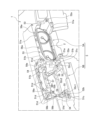
- FIG. 2 is an exploded perspective view showing the vehicle display device and an attachment mechanism.
- FIG. 3 is a perspective view showing the display device mounting portion.
- 4(A) to 4(C) are a front view, a rear view, and a right side view showing the first mounting member.
- 5A and 5B are front and rear perspective views showing the second mounting member.
- FIG. 6A is a front view showing the overlapping portion
- FIG. 6B is a cross-sectional view taken along line AA of FIG. 6A.
- FIG. 7A is a perspective view showing the second display unit, and FIG. 7B is a side cross-sectional view of the main part showing the manner in which the second display unit is attached.
- FIG. 8(A) and 8(B) are a front perspective view and a rear view showing the third mounting member
- FIG. 8(C) is a plan sectional view of a main portion showing the mounting manner of the third mounting member.
- 9A and 9B are top and bottom perspective views of the fourth mounting member.
- FIG. 10 is a perspective view of a main portion showing a manner in which the fourth mounting member is mounted to the second mounting member.
- FIG. 11 is an exploded perspective view showing a vehicle display device and an attachment mechanism according to another embodiment.
- 12A to 12C are a front perspective view, a rear view, and a rear perspective view of a main part of a second display unit according to another embodiment.
- FIG. 13 is a perspective view of the main part from above, showing a mounting manner of the second display unit according to another embodiment.
- the direction in which the vehicle travels is referred to as "forward,” and the direction in which the vehicle travels backward is referred to as "rearward.”
- the left side of the vehicle's direction of travel is referred to as “left,” and the right side of the vehicle's direction of travel is referred to as “right.”
- the left-right direction and the vehicle width direction are synonymous, and the front-rear direction and the vehicle direction are synonymous.
- FIG. 1 is a perspective view showing a vehicle display device provided in an instrument panel
- Fig. 2 is an exploded perspective view showing the vehicle display device and an attachment mechanism.
- an installation panel 1 is disposed in front of an operator seated in a seat.
- the installation panel 1 is hereinafter referred to as the instrument panel.
- Vehicle display devices 2 and 3 are attached to a display device attachment portion 5 formed in a predetermined position in the left-right direction of the instrument panel 1 via an attachment mechanism 4.
- the vehicle display devices 2, 3 have a first display unit 2 arranged above and in front of a steering wheel (not shown) operated by an operator, and a second display unit 3 arranged on one of the left and right sides of the first display unit 2.
- the second display unit 3 is arranged next to the left side of the first display unit 2.
- the first display unit 2 has a display section 2a consisting of a meter device that displays driving support information related to the vehicle being driven, such as vehicle speed and engine RPM.
- the second display unit 3 has a display section 3a consisting of a liquid crystal panel that displays auxiliary driving support information such as route guidance information. Note that the information displayed on the first display unit 2 and the second display unit 3 is not limited to the above.
- the mounting mechanism 4 has a first mounting member 10 , a second mounting member 20 , a third mounting member 30 , and a fourth mounting member 40 .
- the first mounting member 10 is disposed on the rear side of the first display unit 2 and is a frame-shaped member that covers the outer edge of the display section 2a of the first display unit 2.
- the first mounting member 10 is also called a meter bezel.
- the second mounting member 20 is attached and fixed to the display device mounting section 5 on the front side of the second display unit 3 and is a frame-shaped member through which the second display unit 3 is inserted.
- the second mounting member 20 is also called a back panel.
- the third mounting member 30 is formed to be wide in the left-right direction so as to cover the rear side of the first mounting member 10 and the second mounting member 20.
- the third mounting member 30 is also called a front panel.
- the fourth mounting member 40 is a lid-shaped member that covers the upper rear side of the second display unit 3 and the second mounting member 20.
- the fourth mounting member 40 is also called an upper panel.
- the vehicle display devices 2, 3 can be mounted on the instrument panel 1 by mounting the display device mounting portion 5 in the following order: first display unit 2 ⁇ first mounting member 10 ⁇ second mounting member 20 ⁇ second display unit 3 ⁇ third mounting member 30 ⁇ fourth mounting member 40.
- This configuration can be seen in Fig. 2. Specific configurations of the display device mounting portion 5, the vehicle display devices 2, 3, and the mounting mechanism 4 will be described below.
- Figure 3 is a perspective view showing the display device mounting section.
- a first opening 5A that is long in the front-to-rear direction and into which the first display unit 2 is attached is formed in the right half of the display device mounting section 5.
- a second opening 5B is formed in the left half of the display device mounting section 5, with openings formed on the front and top sides so that the second display unit 3 can be attached.
- the second opening 5B is also divided into a front side and a top side by a left-right opening beam portion 5B1 provided at the top of the front side.
- the display device mounting portion 5 is formed with locking holes 51a, 51b, 51c, and 51d, screw fixing holes 52a, 52b, 52c1, and 52c2, clip fixing hole 53, positioning hole 54, locator pins 55, 55, claw locking portions 56a and 56b, and support piece 57. Please refer to FIG. 3 for this configuration.
- the locking holes 51a, 51b, 51c, 51d are arranged along the outer edge of the first opening 5A, and include first locking holes 51a, 51a, 51a to which the first mounting member 10 is locked; second locking holes 51b, 51b, 51b to which the second mounting member 20 is locked; third locking holes 51c, 51c to which the second mounting member 20 is locked; and fourth locking holes 51d, 51d, 51d, 51d, 51d, 51d, 51d to which the fourth mounting member 40 is locked.
- the screw fixing holes 52a, 52b, 52c1, and 52c2 include first screw fixing holes 52a, 52a, two of which are arranged along the lower outer edge of the first opening 5A, into which the first mounting member 10 is screwed, second screw fixing holes 52b, 52b, two of which are arranged along the outer edge of the second opening 5B, into which the second mounting member 20 is screwed, and unit screw fixing holes 52c1, 52c1, 52c2, 52c2, four of which are arranged on the second opening 5B side, into which the second display unit 3 is screwed.
- the unit screw fixing holes include rear unit screw fixing holes 52c1, 52c1 arranged in a pair on the left and right sides along the outer edge of the second opening 5B, and front unit screw fixing holes 52c2, 52c2 arranged on inclined surfaces 59, 59 located within the second opening 5B and in front of the rear unit screw fixing holes 52c1, 52c1.
- the lower surface of the inclined surfaces 59, 59 in which the front unit screw fixing holes 52c2, 52c2 are formed is supported by a support body 100 extended from a deck cloth (not shown) that extends in the left-right direction and supports the instrument panel 1. This configuration can be seen in Figures 3 and 7(B) .
- the clip fixing holes 53, 53 are arranged in a pair in the left-right direction on the upper edge side of the first opening 5A.
- the upper edge of the first mounting member 10 is flexibly fixed to the clip fixing holes 53, 53 using fixing clips (not shown).
- a pair of positioning holes 54, 54 are arranged on both the left and right ends of the second opening 5B.
- the positioning holes 54, 54 position the second mounting member 20 by inserting the second mounting member 20 through them.
- the locator pins 55, 55 are arranged on the left and right sides of the outer edge of the second opening 5B.
- the locator pins 55, 55 are pin-shaped members that protrude rearward and position the second display unit 3.
- the claw locking portions 56a, 56b are arranged on the left and right sides of the upper edge of the first opening 5A, and include first claw locking portions 56a, 56a to which the third mounting member 30 is locked, and second claw locking portions 56b, 56b to which the fourth mounting member 40 is locked, and a pair are arranged in the front-rear direction on the left end side of the upper edge of the second opening 5B.
- the support pieces 57, 57 are arranged on the left and right sides of the rear surface at the center of the left-right direction of the opening beam portion 5B1.
- the support pieces 57, 57 support the fourth mounting member 40 that is attached to the upper surface of the second opening portion 5B.
- each inclined surface 58, 58 has a back panel fixing hole 58a, 58a formed therein for mounting a second display unit 60 of another embodiment described below.
- the above-mentioned configuration of the mounting portion is one example, and the arrangement and number of the locking holes 51a, 51b, 51c, 51d, screw fixing holes 52a, 52b, 52c1, 52c2, clip fixing hole 53, positioning hole 54, locator pin 55, claw locking portions 56a, 56b, and support pieces 57 are not limited to the above-mentioned configuration and can be changed as appropriate depending on the configuration of the vehicle display device 2, 3 and the mounting mechanism 4.
- the specific configurations of the vehicle display devices 2, 3 and the mounting mechanism 4 will be described in the order in which they are mounted to the display device mounting portion 5.
- the first display unit will be described with reference to FIGS. 1 to 3, the first display unit 2 has a display section 2a capable of displaying a meter on the rear side.
- the first display unit 2 is attached by being fitted into the front end side of the first opening 5A formed in a cylindrical shape in the front-rear direction.
- the display section 2a of the first display unit 2 is disposed in a position further forward than the display section 3a of the second display unit 3.
- Figures 4(A) to 4(C) are a front view, a rear view, and a right side view showing the first mounting member.
- the first mounting member 10 is formed in a frame shape that follows the outer edge of the first display unit 2, with the front side attached to the first opening 5A side and the right half of the third mounting member 30 attached to the rear side.
- the first mounting member 10 has a first locking clip 11 , a first screw hole 12 , a through hole 13 , a first front locking hole 14 , a first front through hole 15 , and a first front claw locking portion 16 .
- the first mounting member 10 has a front-to-rear tubular portion 17 that fits into the first opening 5A, an opening 18 that exposes the display portion 2a of the first display unit 2 by opening the front and rear ends of the tubular portion 17, and a first overlapping portion 19 on the left end side that overlaps with the right end side of the second mounting member 20 when viewed from the front.
- a total of three first locking clips 11, 11, 11 are arranged on the front side of the first mounting member 10, and are respectively locked into the first locking holes 51a, 51a, 51a on the display device mounting section 5 side.
- One first locking clip 11 is provided near the right side of the center of the upper edge of the first mounting member 10, and one is provided on each of the left and right ends of the lower edge of the first mounting member 10. This allows the first mounting member 10 to be temporarily fixed in the mounting position on the first opening 5A side.
- the first screw holes 12, 12 are provided on both the left and right ends of the lower part of the frame-shaped first mounting member 10.
- the lower part of the first mounting member 10 can be attached and fixed to the first opening 5A side by fastening the first screw holes 12, 12 and the screw fixing holes 52a, 52a on the first opening 5A side with fixing screws (not shown).
- the flexibility holes 13, 13 are provided on both the left and right ends of the upper edge of the first mounting member 10. Each flexibility hole 13 is formed as a long hole that is long in the left-right direction. By inserting fixing clips (not shown) through the flexibility holes 13, 13 and the clip fixing holes 53, 53 on the display device mounting section 5 side, the upper part of the first mounting member 10 can be fixed to the first opening 5A side.
- the third mounting member 30 is engaged in the first front engaging holes 14.
- the first front engaging holes 14 are arranged in three on the upper edge of the first mounting member 10 at approximately equal intervals in the left-right direction, with one on each of the left and right ends of the lower part of the first mounting member 10. In other words, a total of five first front engaging holes 14, 14, 14, 14, 14, 14 are formed.
- the first front through holes 15 are arranged in alternating rows in the left-right direction, with the first front locking holes 14 and the first front through holes 15 arranged in a row of three on the upper edge side of the first mounting member 10. In the example shown in the figure, two first front through holes 15, 15 are provided.
- the third mounting member 30 is engaged with the first front claw engagement portion 16.
- the first front claw engagement portion 16 is located on the right end side of the first mounting member 10.
- FIGS. 5(A) and 5(B) are a front view and a rear perspective view showing the second mounting member.
- the second mounting member 20 is formed in a frame shape into which the second display unit 3 can be inserted, with its front side attached to the second opening 5B side and the left half of the third mounting member 30 attached to its rear side.
- the second mounting member 20 has a second locking clip 21, a second screw hole 22, a locator pin 23, a second front locking hole 24, a second front through hole 25, a second front claw locking portion 26, a rib 27, and an upper locking hole 28.
- a second overlapping portion 29 is formed on the right end side of the second mounting member 20 so as to overlap the first overlapping portion 19 of the first mounting member 10 in a front view.
- a total of four second locking clips 21, 21, 21, 21 are arranged on the front side of the second mounting member 20, and are respectively locked into the second locking holes 51b, 51b, 51b, 51b on the second opening 5B side.
- Two second locking clips 21 are arranged side by side on the upper right end side of the second mounting member 20, one is provided on the lower right end side of the second mounting member 20, and one is provided on the left end side of the middle part in the vertical direction of the second mounting member 20. This allows the second locking clips 21, 21, 21 to temporarily secure the second mounting member 20 at the mounting position on the second opening 5B side. This configuration can be seen in FIG. 5(B).
- the locator pins 23, 23 are pin-shaped members that protrude forward from the front surface of the second mounting member 20, and are inserted into the positioning holes 54, 54 on the second opening 5B side. Two locator pins 23, 23 are positioned, one on the upper right side and one on the lower left side. This allows the locator pins 23, 23 to smoothly guide the second mounting member 20 toward the mounting position of the second opening 5B.
- the second screw holes 22, 22 are provided in a pair on the upper and lower sides on the left end side of the frame-shaped second mounting member 20.
- the second mounting member 20 can be attached and fixed to the second opening 5B side by fastening the second screw holes 22, 22 to the screw fixing holes 52b, 52b on the display device mounting part 5 side with fixing screws (not shown).
- the third mounting member 30 is engaged in the second front engaging holes 24.
- Four second front engaging holes 24 are arranged in the left-right direction at approximately equal intervals on the upper edge of the second mounting member 20, and one is provided on the left end side of the middle part of the second mounting member 20 in the up-down direction. In other words, a total of five second front engaging holes 24, 24, 24, 24, 24 are formed.
- a part of the third mounting member 30 is inserted into the second front through-hole 25.
- the second front through-holes 25, 25 are provided at both the left and right ends of the lower end of the second mounting member 20.
- the third mounting member 30 is engaged with the second front claw engagement parts 26.
- the second front claw engagement parts 26, 26 are provided on the left and right sides at the center of the lower end of the second mounting member 20.
- Figure 6(A) is a front view showing the overlapping parts
- Figure 6(B) is a cross-sectional view taken along line A-A in Figure 6(A).
- the first overlapping portion 19 is an L-shaped first bent portion formed by bending the edge of the left end of the first mounting member 10 substantially vertically toward the rear.
- the first overlapping portion 19 extends in the up-down direction along the left end side of the first mounting member 10.
- the edge of the left end of the first mounting member 10 is formed in a crank shape from the upper end side downward, thereby forming a step portion 10a that becomes wider toward the left and right outside.
- two step portions 10a are provided in the vertical direction.
- the first overlapping portion 19 extending in the vertical direction is formed in a crank shape, thereby providing two step portions 19a, 19a. This configuration may be seen in FIG. 6(A).
- the second overlapping portion 29 is a second bent portion formed to bend forward in an L-shape.
- the second overlapping portion 29 is formed in a claw shape that meshes with the first overlapping portion 19 from the rear side.
- the second overlapping portion 29 is disposed so as to overlap with the first overlapping portion 19 when viewed from the seat side.
- the right edge of the second mounting member 20 is formed with steps 20a, 20a that conform to the steps 10a, 10a of the first mounting member 10.
- the right edge of the mounting member 20 is formed with steps 20a, 20a that narrow from the top downward and toward the left and right inward. Accordingly, two second overlapping portions 29 are provided on the right edge of the second mounting member 20, offset in the up-down and left-right directions.
- the second overlapping portion 29 is formed in a U-shape that is open toward the front in a plan view at the edge of the right end of the second mounting member 20, thereby forming a groove 29a into which the first overlapping portion 19 engages. This configuration can be seen in FIG. 6(B).
- first overlapping portion 19 and the second overlapping portion 29 have a spigot structure that engages the left end side of the first mounting member 10 with the right end side of the second mounting member 20. This makes it possible to restrict the left-right movement of the second mounting member 20 engaged with the first mounting member 10.
- the vertical ends of the second overlapping portions 29, 29 abut against the step portion 10a of the engaged first mounting member 10, thereby restricting the vertical movement of the second mounting member 20. This configuration can be seen in FIG. 6 (B).
- the installation position of the second mounting member 20 can be smoothly and easily determined. Also, rattling between the first mounting member 10 and the second mounting member 20 arranged side by side is suppressed, and the first display unit 2 and the second display unit 3 can be fixed more firmly to the instrument panel 1 side.
- two claw-shaped second overlapping portions 29 are provided, one above the other, but three or more may be provided, or one second overlapping portion 29 may extend in the vertical direction along the first overlapping portion 19.
- Figure 7(A) is a perspective view showing the second display unit
- Figure 7(B) is a side cross-sectional view of the main part showing the mounting state of the second display unit.
- the second display unit 3 has a display section 3a which is an LCD display section, a box-shaped storage section 6 provided in front of the display section 3a in which a control section is housed, and a pair of mounting pieces 7, 7 attached and fixed to both the left and right ends of the storage section 6.
- the mounting pieces 7, 7 are plate-shaped members in the front-rear direction attached along the side of the storage section 6, and have a first mounting surface 7a with its rear end bent outward to the left and right, and a second mounting surface 7b with its front end bent outward to the left and right.
- the first mounting surface 7a has a flat surface along the display unit 3a, and is formed with unit-side positioning holes 8 into which locator pins 55 on the display device mounting unit 5 are fitted.
- unit fixing holes 9 are formed on the first mounting surface 7a on the left and right outer sides of the unit-side positioning holes 8.
- the second mounting surface 7b has unit fixing holes 9 formed therein, similar to the first mounting surface 7a. This configuration can be seen in FIG.
- Figures 8(A) and 8(B) are a front perspective view and a rear view showing the third mounting member
- Figure 8(C) is a plan sectional view of the main part showing the mounting manner of the third mounting member.
- the third attachment member 30 is formed to be wide in the left-right direction so as to cover the rear sides of the first attachment member 10 and the second attachment member 20.
- the third attachment member 30 has a right half portion which is a first portion surrounding the outer edge of the first display unit 2, and a left half portion which is a second portion covering the rear side of the second attachment member 20.
- the right half of the third mounting member 30 has a notch 30a cut into an inverted U shape at the bottom so that the display section 2a of the first display unit 2 is exposed.
- the left half of the third mounting member 30 has a rectangular opening 30b so that the display section 3a of the second display unit 3 is fitted into it.
- the right half and the left half of the third mounting member 30 are formed to be flush with each other.
- the third mounting member 30 and the display section 3a arranged in the opening 30b are also configured to be flush with each other.
- FIG. 8(A) Third locking clips 31a, 31b, and 31c and third locking claws 32a, 32b, and 32c are arranged along the outer edge on the front side of the third mounting member 30. This configuration can be seen in FIG. 8B.
- the third locking clips 31a, 31b, and 31c include a third locking clip 31a for the bezel, a third locking clip 31b for the back panel, and a third locking clip 31c for the instrument panel.
- Three third bezel locking clips 31a, 31a, 31a, 31a, 31a, 31a, 31a are arranged along the notch 30a in the right half of the front surface of the third mounting member 30, and are locked into the first front locking holes 14, 14, 14, 14, 14 of the first mounting member 10, respectively.
- Three third back panel retaining clips 31b, 31b, 31b, 31b, 31b, 31b, 31b are arranged in a left-right line on the upper left half of the front surface of the third mounting member 30, and are retained in the second front retaining holes 24, 24, 24, 24, 24 of the second mounting member 20, respectively.
- the third instrument panel retaining clips 31c, 31c are arranged on the left and right sides of the lower left half of the front surface of the third mounting member 30, and are retained in the third retaining holes 51c, 51c of the first opening 5A.
- the third locking claws 32a, 32b, and 32c include a third locking claw 32a for the instrument panel, a third locking claw 32b for the bezel, and a third locking claw 32c for the back panel.
- the third instrument panel locking claws 32a, 32a are arranged on the left and right sides of the upper right half of the front surface of the third mounting member 30, and are locked to the first claw locking portions 56a, 56a on the first opening 5A side.
- the third bezel locking claw 32b is located at the top right end of the front surface of the third mounting member 30 and is locked to the first front claw locking portion 16 of the first mounting member 10.
- the third back panel retaining claws 32c, 32c are arranged in a pair on the left and right sides at the bottom of the left half of the front surface of the third mounting member 30, and are retained by the second front retaining claw retaining portions 26, 26 of the second mounting member 20, respectively.
- the third bezel locking clip 31a, the third instrument panel locking claw 32a, and the third bezel locking claw 32b are arranged in an inverted U-shape along the cutout 30a on the front side of the right half of the third mounting member 30.
- the third bezel locking clip 31a and the third instrument panel locking claw 32a are arranged alternately.
- the third back panel fastening clip 31b, the third instrument panel fastening clip 31c, and the third back panel fastening claw 32c are arranged side by side along the opening 30b on the front side of the left half of the third mounting member 30. This configuration can be seen in FIG. 8(B).
- Figures 9(A), 9(B) and 10 are a top perspective view and a bottom perspective view of the fourth mounting member
- Figure 10 is a perspective view of the main parts showing the manner in which the fourth mounting member is mounted to the second mounting member.
- the fourth mounting member 40 is a plate-like member extending in the front-rear direction so as to straddle the upper end sides of the display device mounting portion 5 and the second mounting member 20.
- the fourth mounting member 40 is a lid-like member that covers the front of the opening beam portion 5B1 of the second opening 5B.
- a side portion 40a is formed on the left end side of the fourth mounting member 40, which is bent downward so as to cover the gap formed between the instrument panel 1 and the second display unit 3.
- the fourth mounting member 40 has fourth locking clips 41a, 41b arranged side by side along the outer edge of the lower surface side, and a fourth locking claw 42 locked along the side surface portion 40a.
- the fourth locking clips 41a, 41b include a fourth locking clip 41a for the instrument panel and a fourth locking clip 41b for the back panel.
- Three fourth instrument panel fastening clips 41a are provided along the front edge of the underside of the fourth mounting member 40, two on each of the left and right ends. That is, in the illustrated example, seven fourth instrument panel fastening clips 41a, 41a, 41a, 41a, 41a, 41a, 41a, 41a, 41a, 41a, 41a, 41a, 41a, 41a are provided along the outer edge of the underside of the fourth mounting member 40, and are fastened to the fourth fastening holes 51d, 51d, 51d, 51d, 51d, 51d, 51d of the second opening 5B, respectively.
- the fourth back panel retaining clips 41b, 41b are arranged in a pair at the rear end center of the underside of the fourth mounting member 40, and are retained in the upper retaining holes 28, 28 formed in the rib 27 of the second mounting member 20. See FIG. 10 for this configuration.
- the fourth locking claws 42, 42 are arranged in a pair along the lower end side of the left end side portion 40a of the lower surface of the fourth mounting member 40, and are each locked to the second locking claw portions 56b, 56b of the second opening 5B.
- each of the above-mentioned locking clips is a locking piece with a pair of barbs that move back and forth or that elastically deform when inserted into each locking hole.
- the above-mentioned locking claw is a locking piece with a single barb that locks into each locking portion, and is thinner and less expensive than the locking clip.
- the fixing clip that is inserted into the flexibility hole 13 and clip fixing hole 53 is a rivet-like fastener with barbs that do not move back and forth.
- the above-mentioned fixing screw is a fastener that is screwed between each component.
- the locking devices and fasteners that attach and fix each component are not limited to the above examples.
- the first attachment member 10 can be temporarily fixed at a predetermined attachment position by engaging the first locking clips 11, 11, 11 with the first locking holes 51a, 51a, 51a on the first opening 5A side. Thereafter, the first screw holes 12, 12 at the lower part of the first mounting member 10 can be firmly attached and fixed to the instrument panel 1 side by fastening the first screw holes 12, 12 at the lower part of the first mounting member 10 to the screw fixing hole 52a on the first opening 5A side with a fixing screw. This allows the first mounting member 10 to be smoothly positioned at the mounting position and fixed to the first opening 5A with the fixing screws.
- the upper part of the first mounting member 10 is secured with a fixing clip to the wide lateral openings 13, 13 and the clip fixing hole 53 on the first opening 5A side. This allows the upper part of the first mounting member 10 to be attached and fixed to the first opening 5A side while leaving some room for deformation.
- the lateral openings 13, 13 may be configured to be wide so that there is some room for the fixing clip not only in the lateral direction but also in the vertical direction.
- the first mounting member 10 Due to its positioning, the upper side of the first mounting member 10 is likely to be exposed to sunlight for long periods of time. For this reason, if the first mounting member 10 is made of a resin material, the first mounting member 10 may undergo thermal deformation. In response to this, the first mounting member 10 has a flexibility hole 13 at its top that can absorb some of the thermal deformation of the upper part of the first mounting member 10, effectively preventing the first mounting member 10 from cracking due to thermal deformation.
- the second mounting member 20 By inserting the locator pins 23, 23 into the positioning holes 54, 54 on the second opening 5B side, the second mounting member 20 can be smoothly guided toward a predetermined mounting position. Thereafter, the second overlapping portion 29 on the right end side of the second mounting member 20 engages with the first overlapping portion 19 on the left end side of the first mounting member 10 using a spigot structure, thereby enabling the second mounting member 20 to be stably held in the mounting position. Thereafter, the second mounting member 20 can be temporarily fixed at a predetermined mounting position by engaging the second locking clips 21, 21, 21, 21 with the second locking holes 51b, 51b, 51b, 51b on the second opening 5B side.
- the second mounting member 20 can be firmly attached and fixed to the instrument panel 1 by fastening the second screw holes 22, 22 arranged in a pair above and below on the left end side of the second mounting member 20 to the screw fixing hole 52b on the first opening 5A side with a fixing screw. This allows the second mounting member 20 to be smoothly and easily positioned at the mounting position and fixed to the second opening 5B with the fixing screws.
- the second display unit 3 By inserting the locator pins 55, 55 into the unit side positioning holes 8, the second display unit 3 can be smoothly guided toward a predetermined mounting position. Thereafter, the second display unit 3 can be attached and fixed to the first mounting surface 7a side on the second opening 5B side by fastening the unit fixing hole 9 on the first mounting surface 7a side and the rear unit screw fixing holes 52c1, 52c1 on the display device mounting portion 5 side with fixing screws. Similarly, the second display unit 3 can be attached and fixed to the second mounting surface 7b side of the second opening 5B by fastening the unit fixing hole 9 on the second mounting surface 7b side to the front unit screw fixing holes 52c2, 52c2 formed on the inclined surface 59 of the second opening 5B on the display device mounting portion 5 side with fixing screws. This allows the second display unit 3 to be smoothly and easily positioned at the mounting position and fixed to the second opening 5B with the fixing screws.
- the right half of the third mounting member 30 can be attached to the first opening 5A side by engaging the five bezel third locking clips 31a arranged on the right half with each of the first front locking holes 14 of the first mounting member 10, engaging the five back panel third locking clips 31b arranged on the left half with each of the second front locking holes 24 of the second mounting member 20, and engaging the pair of instrument panel third locking clips 31c with each of the third locking holes 51c of the first opening 5A.
- the third instrument panel fastening clips 31c, 31c are inserted through the second front through holes 25, 25 of the front second mounting member 20, and are thereby fastened to the third fastening holes 51c, 51c on the second opening 5B side.
- the third mounting member 30 can be mounted on the second opening 5B side by engaging the two third engaging claws 32a for the instrument panel located on the right half with the first claw engaging portions 56a on the first opening 5A side, the third engaging claw 32b for the bezel located on the right end side with the first front claw engaging portion 16 of the first mounting member 10, and the two third engaging claws 32c for the back panel located on the lower end side of the left half with the second front claw engaging portion 26 of the second mounting member 20.
- the instrument panel third locking claws 32a, 32a are inserted into the first front through-holes 15, 15 of the front first mounting member 10, and are thereby locked to the first claw locking portions 56a, 56a of the first opening 5A, respectively. This configuration can be seen in Fig. 8(C).
- the third mounting member 30 can be smoothly attached to the display device mounting section 5 simply by pressing it against the rear surfaces of the first mounting member 10 and the second mounting member 20. At this time, the third mounting member 30 can be attached to the display device mounting section 5 without using fixing screws by using a total of 12 locking clips and a total of 5 locking claws. Furthermore, the third mounting member 30 is engaged not only with the first mounting member 10 and the second mounting member 20 on the front side, but also with the display device mounting portion 5 disposed further forward of the first mounting member 10 and the second mounting member 20. Therefore, the third mounting member 30 can be firmly attached to the instrument panel 1 side only with the third engaging clips 31a, 31b, 31c and the third engaging claws 32a, 32b, 32c.
- the third bezel locking clips 31a attached to the first mounting member 10 side and the third instrument panel locking claws 32a attached to the first opening 5A side are arranged alternately in the left-right direction on the upper edge side of the right half of the third mounting member 30. This allows the third mounting member 30 to be attached to the display device mounting portion 5 side more stably and firmly.
- the fourth mounting member 40 has seven fourth locking clips 41a for the instrument panel that are each locked into the fourth locking holes 51d on the top surface of the second opening 5B, and two fourth locking clips 41b for the back panel that are each locked into the upper locking holes 28, 28 formed in the rib 27 of the second mounting member 20. This allows the fourth mounting member 40 to be smoothly mounted on the upper surface side of the second opening 5B.
- the rib 27 of the second mounting member 20 is supported from below by the support pieces 57, 57 on the second opening 5B side. Therefore, when the fourth back panel fastening clips 41b, 41b are fastened to the upper fastening holes 28, 28, the fourth mounting member 40 can restrict the rib 27 from bending downward. In other words, the fourth back panel fastening clips 41b, 41b can be stably fastened to the upper fastening holes 28, 28. This configuration can be seen in FIG. 10.
- the fourth mounting member 40 similarly has fourth locking claws 42 arranged in two positions, front and rear, along the lower end side of the side surface portion 40a, which lock into the second locking portions 56b, 56b of the second opening 5B.
- the third mounting member 30 and the fourth mounting member 40 are connected to the display device mounting part 5 side only with the third locking clips 31a, 31b, 31c, the fourth locking clips 41a, 41b, the third locking claws 32a, 32b, 32c, and the fourth locking claw 42, without using fixing screws.
- the fasteners are not positioned in a position visible to the operator in the seat. This results in a neat and tidy appearance around the vehicle display devices 2, 3.
- FIG. 11 is an exploded perspective view showing a vehicle display device and attachment mechanism of another embodiment
- Fig. 12(A) to Fig. 12(C) are a front perspective view, a rear view, and a rear perspective view of the main part of the second display unit of another embodiment
- Fig. 13 is a perspective view from above of the main part showing the attachment mode of the second display unit of another embodiment.
- the vehicle display device and attachment mechanism will be described with respect to differences from the above-mentioned examples.
- the vehicle display device 2 , 60 has a first display unit 2 and a second display unit 60 .
- the mounting mechanism 4 has a first mounting member 10 and a fourth mounting member 40 . According to the mounting mechanism 4, the vehicle display device 2, 60 can be mounted on the instrument panel 1 side by mounting the first display unit 2 ⁇ first mounting member 10 ⁇ second display unit 60 ⁇ fourth mounting member 40 on the display device mounting portion 5 side in that order.
- the second display unit 60 has a display section 61 which is a liquid crystal panel that displays various information, a box-shaped storage section 90 which is disposed in front of the display section 61 and stores the control section, a front panel 70 which extends in the left-right direction so as to flushly cover the rear surface of the display section 61 and the outer edge of the first mounting member 10, and a back panel 80 which covers the front surface of the left half of the front panel 70.
- a display section 61 which is a liquid crystal panel that displays various information
- a box-shaped storage section 90 which is disposed in front of the display section 61 and stores the control section
- a front panel 70 which extends in the left-right direction so as to flushly cover the rear surface of the display section 61 and the outer edge of the first mounting member 10
- a back panel 80 which covers the front surface of the left half of the front panel 70.
- the front panel 70 is a plate-like member extending in the left-right direction so as to cover the entire area from the first opening 5A to the second opening 5B with a flush plane, and a notch 70a is formed in the right half by cutting out the lower end in an inverted U-shape so as to expose the display section 2a of the first display unit 2.
- a light-transmitting material is used for at least the left half of the front panel 70.
- the front panel 70 is configured so that the display content of the display unit 3a arranged on the front side of the front panel 70 can be seen from behind the front panel 70.
- third locking clips 31a, 31a, 31a, 31a, 31a, 31a for the bezel, third locking claws 32a, 32a for the instrument panel, and third locking claws 32b for the bezel are arranged in a row along the cutout portion 70a.
- the third bezel clip 31a, the third instrument panel clip 32a, and the third bezel clip 32b are arranged in an inverted U-shape along the notch 70a.
- the third bezel clip 31a and the third instrument panel clip 32a are arranged alternately on the upper edge side extending in the left-right direction. This configuration can be seen in FIG. 12B.
- a back panel 80 is fixed integrally to the left half of the front surface of the front panel 70 .
- the back panel 80 covers the left half of the front surface of the front panel 70 so as to surround the storage section 90.
- the back panel 80 is fixed integrally to the front surface side of the front panel 70, and the display section 61 is stored between the back panel 80 and the front panel 70.
- Upper mounting pieces 81, 81 and locking protrusions 82, 82 are provided on the front side of the back panel 80.
- the back panel 80 is a metal member formed by die casting, and the upper mounting pieces 81, 81 and the locking protrusions 82, 82 are also integrally formed.
- the upper mounting pieces 81, 81 are attached and fixed to the inclined surfaces 58, 58 formed on both the left and right ends of the opening beam portion 5B1.
- the upper mounting pieces 81, 81 are plate-shaped members extending forward from the top of the front surface of the back panel 80, and are provided in pairs on both the left and right ends.
- Mounting piece fixing holes 81a, 81a are formed on the front end sides of the pair of upper mounting pieces 81, 81 for fixing to the inclined surfaces 58 on the opening beam portion 5B1 side.
- a pair of locking projections 82 are provided on the left and right inside the pair of left and right upper mounting pieces 81, 81.
- the locking projections 82 have upper locking holes 82a, 82a in the vertical direction to which the fourth mounting member 40 is locked. Please refer to Figures 12(B) and 13 for this configuration.
- the accommodation portion 90 has a pair of lower mounting pieces 91, 91 fixed to both left and right ends.
- the lower mounting piece 91 has a front end that is bent outward in the left-right direction to form a mounting surface 92.
- the mounting surface 92 is formed with unit fixing holes 93 for screwing the accommodation portion 90 to the inclined surfaces 59, 59 on the second opening 5B side. This configuration can be seen in FIG. 12C.
- the right half of the second display unit 60 can be attached and fixed to the first opening 5A side by engaging the third bezel locking clip 31a with the first front locking hole 14 of the first mounting member 10, engaging the third instrument panel locking claw 32a with the first claw locking portion 56a on the first opening 5A side, and engaging the third bezel locking claw 32b with the first front claw locking portion 16 of the first mounting member 10.
- the upper mounting piece 81 can be fixed to the inclined surfaces 58, 58 on the opening beam portion 5B1 side by fastening the mounting piece fixing hole 81a of the upper mounting piece 81 to the back panel fixing holes 58a, 58a formed in the inclined surface 58 with a fixing screw (not shown).
- a fixing screw not shown
- This configuration can be seen in Figures 12(A) and 13.
- the unit fixing holes 93, 93 of the lower mounting pieces 91, 91 to the front unit screw fixing holes 52c2, 52c2 on the second opening 5B side with fixing screws, the lower part of the back panel 80 can be fixed to the inclined surfaces 59, 59 on the second opening 5B side. This allows the left half of the second display unit 60 to be fixed to the second opening 5B side.
- the upper mounting piece 81 and the lower mounting piece 91 are attached to the second opening 5B and the respective inclined surfaces 58, 59 on the opening beam portion 5B1 side by fixing screws that are screwed in the vertical direction, the installation work of the left half of the second display unit 60 to the second opening 5B can be performed from the top side of the second opening 5B. Furthermore, since the fixing screws can be arranged in positions that are not visible to the operator seated in the seat, the appearance of the vehicle display device 2, 60 mounted on the instrument panel 1 can be kept clean.
- the support pieces 57 formed on the opening beam portion 5B1 may be arranged on both the left and right sides of the locking protrusions 82, so that the support pieces 57 function as positioning members for positioning the second display unit 60 in a predetermined position.
- the fourth mounting member 40 has seven fourth locking clips 41a for the instrument panel that are each locked into the fourth locking holes 51d on the top surface of the second opening 5B, and two fourth locking clips 41b for the back panel that are locked into the upper locking holes 82a, 82a formed in the locking protrusion 82.
- the fourth mounting member 40 has fourth locking claws 42 arranged at two positions, front and rear, along the lower end side of the side surface portion 40a, which are locked to the second claw locking portions 56b, 56b of the second opening 5B.
- the above-mentioned configuration allows the display device mounting portion 5 formed on the instrument panel 1 to be mounted with either a vehicle display device 2, 60 having a second display unit 60 in which the front panel 70 and back panel 80 are integrally molded, or a vehicle display device 2, 3 including a second display unit 3 in which the third mounting member 30 and second mounting member 20, which correspond to the front panel 70 and back panel 80, are separately constructed, providing high versatility.
- the vehicle display devices 2, 3, 60 are formed such that the front panel, which extends from the left-right center to the right end of the instrument panel 1 that extends in the left-right direction, has a first portion that surrounds the outer edge of the first display portion located in a recessed position forward of the right half of the front panel, and a second portion where the second display portion located in the left half of the front panel is displayed, are flush with each other. Furthermore, the vehicle display devices 2, 3, 60 are attached so that the fixing device between them and the display device mounting portion 5 is not visible. This results in a clean appearance for the vehicle display devices 2, 3, 60 provided on the instrument panel 1.
- the vehicle display devices 2, 3 may be arranged symmetrically depending on the position of the driver's seat.
- the present invention is not limited to the above-described embodiment, and can be modified or improved as appropriate.
- a mounting structure for a vehicle display device in which a vehicle display device that displays information about a vehicle is mounted to a mounting portion provided on an installation panel extending in a vehicle width direction, comprising:
- the vehicle display device includes a first display unit disposed on one side of the mounting portion in a vehicle width direction, a second display unit disposed on the other side of the mounting portion in the vehicle width direction, and an attachment mechanism that attaches and fixes the first display unit and the second display unit to the mounting portion
- the attachment mechanism includes: a first attachment member that is formed along an outer edge of the first display unit and is connected to the attachment portion while being disposed on the rear side of the first display unit; a second mounting member connected to the mounting portion at a position where the second display unit is installed; a third mounting member extending in a vehicle width direction so as to cover rear sides of the first mounting member and the second mounting member and connected to the mounting portion at the rear sides of the first mounting member and the second mounting member, An overlapping portion is provided so that
- the first mounting member and the second mounting member for attaching each display unit can be fixed to the mounting portion more firmly and stably while reducing the number of fasteners used to fix the first mounting member and the second mounting member to the mounting portion.
- the second mounting member is disposed on the rear side of the first mounting member.
- An end portion of the first mounting member has a first bent portion bent rearward, The end of the second mounting member has a second bent portion bent forward, The first bent portion and the second bent portion are engaged with each other at the overlapping portion.
- the mounting structure for a vehicle display device according to any one of (1) to (2). According to this configuration, the overlapping portion is engaged so that the L-shaped ends bent in the fore-and-aft direction mesh with each other, thereby suppressing rattling in the vehicle width direction.
- a flexible mechanism that allows displacement of the first mounting member is provided on an upper portion of the first mounting member that is connected to the mounting portion.
- the adapting mechanism includes a long hole formed in an upper portion of the first mounting member, and a fastener for fastening the upper portion of the first mounting member to the mounting portion via the long hole,
- the long hole is formed wide at least in the vehicle width direction.
- a lower portion of the first mounting member is fixed to the mounting portion using a fastener that is screwed into the mounting portion.
- the third mounting member is provided with a first connecting portion connected to the first mounting member, a second connecting portion connected to the second mounting member, and a third connecting portion connected to the mounting portion, the first connecting portion and the second connecting portion extending forward.
- the mounting structure for a vehicle display device according to any one of (1) to (6). According to this configuration, the third mounting member can be fixed not only to the mounting portion but also to the first mounting member and the second mounting member, thereby improving the rigidity of the third mounting member.
- the first connecting portion and the third connecting portion are arranged alternately in a vehicle width direction.
- a plate-shaped fourth mounting member is provided to be fixed to an upper portion of the mounting portion and an upper portion of the second mounting member so as to straddle the mounting portion and the second mounting member.
- a mounting structure for a vehicle display device according to any one of (1) to (8). According to this configuration, the upper mounting member can connect and fix the mounting portion and the second mounting member, thereby improving the overall rigidity of the vehicle display device.
- the second mounting member has an upper end formed with an extension portion having a locking hole and extending forward, A locking piece is provided at a rear end of the fourth mounting member to lock the second mounting member through the locking hole.
- a mounting structure for a display device for a vehicle According to this configuration, the connecting portion between the upper mounting member and the second mounting member is invisible, resulting in a neat finish.
- a support piece that supports the extension part from below is provided on the mounting part.
Landscapes
- Engineering & Computer Science (AREA)
- Chemical & Material Sciences (AREA)
- Combustion & Propulsion (AREA)
- Transportation (AREA)
- Mechanical Engineering (AREA)
- Instrument Panels (AREA)
Priority Applications (2)
| Application Number | Priority Date | Filing Date | Title |
|---|---|---|---|
| JP2025509473A JPWO2024201867A1 (https=) | 2023-03-30 | 2023-03-30 | |
| PCT/JP2023/013088 WO2024201867A1 (ja) | 2023-03-30 | 2023-03-30 | 車両用表示装置の取付構造 |
Applications Claiming Priority (1)
| Application Number | Priority Date | Filing Date | Title |
|---|---|---|---|
| PCT/JP2023/013088 WO2024201867A1 (ja) | 2023-03-30 | 2023-03-30 | 車両用表示装置の取付構造 |
Publications (1)
| Publication Number | Publication Date |
|---|---|
| WO2024201867A1 true WO2024201867A1 (ja) | 2024-10-03 |
Family
ID=92903668
Family Applications (1)
| Application Number | Title | Priority Date | Filing Date |
|---|---|---|---|
| PCT/JP2023/013088 Ceased WO2024201867A1 (ja) | 2023-03-30 | 2023-03-30 | 車両用表示装置の取付構造 |
Country Status (2)
| Country | Link |
|---|---|
| JP (1) | JPWO2024201867A1 (https=) |
| WO (1) | WO2024201867A1 (https=) |
Citations (3)
| Publication number | Priority date | Publication date | Assignee | Title |
|---|---|---|---|---|
| JPS6045434A (ja) * | 1983-08-20 | 1985-03-11 | Nissan Motor Co Ltd | インストルメントパネルとインストステイとの連結構造 |
| JPH11321385A (ja) * | 1998-05-15 | 1999-11-24 | Inoac Corporation:Kk | 車両用フェーシア |
| US20200269698A1 (en) * | 2017-11-08 | 2020-08-27 | Lg Electronics Inc. | Vehicle instrument panel |
-
2023
- 2023-03-30 JP JP2025509473A patent/JPWO2024201867A1/ja active Pending
- 2023-03-30 WO PCT/JP2023/013088 patent/WO2024201867A1/ja not_active Ceased
Patent Citations (3)
| Publication number | Priority date | Publication date | Assignee | Title |
|---|---|---|---|---|
| JPS6045434A (ja) * | 1983-08-20 | 1985-03-11 | Nissan Motor Co Ltd | インストルメントパネルとインストステイとの連結構造 |
| JPH11321385A (ja) * | 1998-05-15 | 1999-11-24 | Inoac Corporation:Kk | 車両用フェーシア |
| US20200269698A1 (en) * | 2017-11-08 | 2020-08-27 | Lg Electronics Inc. | Vehicle instrument panel |
Also Published As
| Publication number | Publication date |
|---|---|
| JPWO2024201867A1 (https=) | 2024-10-03 |
Similar Documents
| Publication | Publication Date | Title |
|---|---|---|
| JP2005035526A (ja) | 自動二輪車 | |
| JP2018122657A (ja) | 車室内前部構造 | |
| JP6852422B2 (ja) | 車室内前部構造 | |
| WO2024201867A1 (ja) | 車両用表示装置の取付構造 | |
| WO2024201866A1 (ja) | 車両用表示装置、及び車両用表示装置の取付構造 | |
| JP2010132242A (ja) | 自動車のドア用トリムボード及び自動車のバックドア | |
| JP2010000897A (ja) | 車両のインストルメントパネル部構造 | |
| JP2010023749A (ja) | 車両用インストルメントパネル上面部支持構造 | |
| WO2017010431A1 (ja) | インストルメントパネル | |
| JP2018016199A (ja) | 車両用補機のブラケット取付構造 | |
| JP4973978B2 (ja) | コンソールボックスの取付け構造 | |
| CN102958780B (zh) | 机动车的转向装置 | |
| JP5047044B2 (ja) | メータ取付構造 | |
| JP7487540B2 (ja) | 支持構造および電子機器 | |
| JP7436414B2 (ja) | 車両構造 | |
| JP7491231B2 (ja) | 車両 | |
| CN101574947B (zh) | 内装件的安装构造 | |
| CN105711419A (zh) | 车辆仪表板的附件安装结构 | |
| JP6992501B2 (ja) | 車両のインストルメントパネルの構造 | |
| JP6438988B2 (ja) | 車両用メータ構造 | |
| JP7636721B2 (ja) | 車両用インストルメントパネル構造 | |
| JP4466317B2 (ja) | 車両用インストルメントパネルへの機器の取付構造 | |
| WO2017002191A1 (ja) | Ecuブラケット及び車両 | |
| JP7732239B2 (ja) | 車両用インストルメントパネル構造 | |
| JP7626010B2 (ja) | 車載装置 |
Legal Events
| Date | Code | Title | Description |
|---|---|---|---|
| 121 | Ep: the epo has been informed by wipo that ep was designated in this application |
Ref document number: 23930505 Country of ref document: EP Kind code of ref document: A1 |
|
| WWE | Wipo information: entry into national phase |
Ref document number: 2025509473 Country of ref document: JP |
|
| NENP | Non-entry into the national phase |
Ref country code: DE |
|
| 122 | Ep: pct application non-entry in european phase |
Ref document number: 23930505 Country of ref document: EP Kind code of ref document: A1 |