WO2024201754A1 - 車両サービス管理システム、車両サービス管理装置、車両サービス管理方法及び記録媒体 - Google Patents
車両サービス管理システム、車両サービス管理装置、車両サービス管理方法及び記録媒体 Download PDFInfo
- Publication number
- WO2024201754A1 WO2024201754A1 PCT/JP2023/012671 JP2023012671W WO2024201754A1 WO 2024201754 A1 WO2024201754 A1 WO 2024201754A1 JP 2023012671 W JP2023012671 W JP 2023012671W WO 2024201754 A1 WO2024201754 A1 WO 2024201754A1
- Authority
- WO
- WIPO (PCT)
- Prior art keywords
- vehicle
- user
- item
- lost
- notification
- Prior art date
- Legal status (The legal status is an assumption and is not a legal conclusion. Google has not performed a legal analysis and makes no representation as to the accuracy of the status listed.)
- Ceased
Links
Images













Classifications
-
- B—PERFORMING OPERATIONS; TRANSPORTING
- B60—VEHICLES IN GENERAL
- B60R—VEHICLES, VEHICLE FITTINGS, OR VEHICLE PARTS, NOT OTHERWISE PROVIDED FOR
- B60R25/00—Fittings or systems for preventing or indicating unauthorised use or theft of vehicles
- B60R25/20—Means to switch the anti-theft system on or off
-
- E—FIXED CONSTRUCTIONS
- E05—LOCKS; KEYS; WINDOW OR DOOR FITTINGS; SAFES
- E05B—LOCKS; ACCESSORIES THEREFOR; HANDCUFFS
- E05B49/00—Electric permutation locks; Circuits therefor ; Mechanical aspects of electronic locks; Mechanical keys therefor
-
- G—PHYSICS
- G06—COMPUTING OR CALCULATING; COUNTING
- G06Q—INFORMATION AND COMMUNICATION TECHNOLOGY [ICT] SPECIALLY ADAPTED FOR ADMINISTRATIVE, COMMERCIAL, FINANCIAL, MANAGERIAL OR SUPERVISORY PURPOSES; SYSTEMS OR METHODS SPECIALLY ADAPTED FOR ADMINISTRATIVE, COMMERCIAL, FINANCIAL, MANAGERIAL OR SUPERVISORY PURPOSES, NOT OTHERWISE PROVIDED FOR
- G06Q30/00—Commerce
- G06Q30/02—Marketing; Price estimation or determination; Fundraising
- G06Q30/0207—Discounts or incentives, e.g. coupons or rebates
-
- G—PHYSICS
- G06—COMPUTING OR CALCULATING; COUNTING
- G06Q—INFORMATION AND COMMUNICATION TECHNOLOGY [ICT] SPECIALLY ADAPTED FOR ADMINISTRATIVE, COMMERCIAL, FINANCIAL, MANAGERIAL OR SUPERVISORY PURPOSES; SYSTEMS OR METHODS SPECIALLY ADAPTED FOR ADMINISTRATIVE, COMMERCIAL, FINANCIAL, MANAGERIAL OR SUPERVISORY PURPOSES, NOT OTHERWISE PROVIDED FOR
- G06Q30/00—Commerce
- G06Q30/06—Buying, selling or leasing transactions
- G06Q30/0645—Rental transactions; Leasing transactions
Definitions
- the present invention relates to a vehicle service management system, a vehicle service management device, a vehicle service management method, and a recording medium.
- Patent Document 1 describes a shared vehicle system equipped with an ETC on-board unit that uses ETC cards.
- the shared vehicle system described in Patent Document 1 includes a means for detecting whether an operation to end use of a shared vehicle has been performed, and a means for detecting whether an ETC card is inserted into the ETC onboard unit.
- the shared vehicle system described in Patent Document 1 detects that an operation to end use of a shared vehicle has been performed and detects that an ETC card is inserted into the ETC onboard unit, it invalidates the completion of the operation to end use of the shared vehicle.
- Patent Document 1 also describes that if an ETC card is detected to be inserted into the ETC onboard unit when an operation to end use of the shared vehicle is detected, a warning is issued by at least one of display and audio. Patent Document 1 also describes that after the completion of the operation to end use of the shared vehicle is invalidated, a notification is sent to the communication device owned by the user of the shared vehicle.
- one example of the objective of the present invention is to provide a vehicle service management system, a vehicle service management device, a vehicle service management method, a recording medium, and the like that can easily enable users to retrieve items left behind in a vehicle.
- an end information acquisition means for acquiring end information indicating that a user has ended use of the vehicle;
- a left-behind detection means for detecting an item left behind in the vehicle;
- a lost property notification means for issuing a lost property notification indicating that the item has been left behind when the usage end information is acquired and the item has been detected;
- a collection schedule acquiring means for acquiring a collection schedule indicating a time when the user will return to the parking location of the vehicle to collect the left-behind item in response to the lost-behind item notification;
- an unlocking control means for controlling unlocking of the vehicle,
- a vehicle service management system is provided, wherein controlling the unlocking of the vehicle includes allowing the user to unlock the vehicle based on the scheduled collection time.
- an end information acquisition means for acquiring end information indicating that a user has ended use of the vehicle; a detection information acquiring means for acquiring detection information indicating that an item left behind in the vehicle has been detected; a lost property notification means for issuing a lost property notification indicating that the item has been left behind when the usage end information and the detection information are both acquired; a collection schedule acquiring means for acquiring a collection schedule indicating a time when the user will return to the parking location of the vehicle to collect the left-behind item in response to the lost-behind item notification; a vehicle instruction means for transmitting an unlock control instruction for controlling unlocking of the vehicle, A vehicle service management device is provided, wherein the unlocking control instruction includes an instruction for allowing the user to unlock the vehicle based on the scheduled collection time.
- One or more computers Acquire end-of-use information indicating that the user will end use of the vehicle; Detecting items left behind in the vehicle; When the usage end information is acquired and the left-behind property is detected, a lost property notification is issued to indicate that the left-behind property has been found; In response to the notification of the lost property, a planned collection time is obtained that indicates a time when the user will return to the parking location of the vehicle to collect the lost property; controlling the unlocking of the vehicle; A vehicle service management method is provided, wherein controlling the unlocking of the vehicle includes allowing the user to unlock the vehicle based on the scheduled collection time.
- a lost property notification is issued to indicate that the left-behind property has been found;
- a planned collection time is obtained that indicates a time when the user will return to the parking location of the vehicle to collect the lost property;
- a recording medium is provided having a program recorded thereon, the program controlling the unlocking of the vehicle including allowing the user to unlock the vehicle based on the scheduled collection time.
- One aspect of the present invention makes it easier for users to retrieve items left behind in a vehicle.
- FIG. 1 is a diagram showing an overview of a vehicle service management system according to a first embodiment
- 1 is a diagram showing an overview of a vehicle service management device according to a first embodiment
- 11 is a flowchart illustrating an example of a first vehicle service management process.
- 10 is a flowchart illustrating an example of a second vehicle service management process.
- 1 is a diagram illustrating an example of the configuration of a vehicle service management system according to a first embodiment.
- FIG. 2 is a diagram illustrating an example of a functional configuration of a vehicle service management device according to the first embodiment.
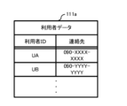
- FIG. 4 is a diagram showing an example of user data.
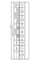
- FIG. 11 is a diagram showing an example of usage schedule data.
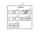
- FIG. 2 is a diagram illustrating an example of a functional configuration of a user terminal according to the first embodiment.
- FIG. 2 is a diagram illustrating an example of a functional configuration of an in-vehicle device according to the first embodiment.
- FIG. 2 is a diagram illustrating an example of a physical configuration of a management device according to the first embodiment.
- FIG. 2 is a diagram illustrating an example of the physical configuration of a user terminal according to the first embodiment.
- FIG. 2 is a diagram illustrating an example of the physical configuration of an in-vehicle device according to the first embodiment.
- FIG. 11 is a diagram illustrating an example of the flow of a user management process according to the first embodiment.
- FIG. 11 is a diagram showing an example of the flow of a usage schedule management process according to the first embodiment.
- FIG. 11 is a diagram illustrating an example of a flow of a start-of-use process according to the first embodiment.
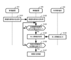
- FIG. 11 is a diagram illustrating an example of the flow of a usage termination process according to the first embodiment.
- FIG. 11 is a diagram illustrating an example of the flow of a usage termination process according to the first embodiment.
- FIG. 11 is a diagram illustrating an example of a functional configuration of a management device according to a second embodiment;
- FIG. 11 is a diagram illustrating an example of a functional configuration of an in-vehicle device according to a second embodiment.
- FIG. 11 is a diagram showing an example of the flow of a usage termination process according to the second embodiment.
- FIG. 11 is a diagram illustrating an example of a flow of a start-of-use process according to the first embodiment.
- FIG. 11 is a diagram illustrating an example of the flow of a usage termination process according to the first embodiment.
- FIG. 11 is a diagram illustrating an example of a functional
- FIG. 11 is a diagram illustrating an example of a functional configuration of a management device according to a third embodiment.
- FIG. 13 is a diagram illustrating an example of the functional configuration of a notification request unit according to a third embodiment.
- FIG. 11 is a diagram illustrating an example of the functional configuration of a user terminal according to a third embodiment.
- FIG. 11 is a diagram illustrating an example of a functional configuration of an in-vehicle device according to a third embodiment.
- FIG. 13 is a diagram showing an example of the flow of a usage termination process according to the third embodiment.
- FIG. 13 is a diagram illustrating an example of a functional configuration of a management device according to a fourth embodiment.
- FIG. 13 is a diagram illustrating an example of a functional configuration of a communication unit according to a fourth embodiment.
- FIG. 13 is a diagram illustrating an example of the functional configuration of a user terminal according to a fourth embodiment.
- FIG. 13 is a diagram showing an example of the flow of a first response response process according to the fourth embodiment.
- (Embodiment 1) (overview) 1 is a diagram showing an overview of a vehicle service management system 100 according to embodiment 1.
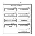
- the vehicle service management system 100 includes a completion information acquisition unit 115, a lost property detection unit 151, a lost property notification unit 117, a collection schedule acquisition unit 118, and an unlocking control unit 152.
- the end information acquisition unit 115 acquires end-of-use information indicating that the user has ended use of the vehicle.
- the lost property detection unit 151 detects items left behind in the vehicle.
- the lost-item notification unit 117 issues a lost-item notification indicating that an item has been left behind.
- the collection schedule acquisition unit 118 acquires, in response to the lost item notification, the planned collection time indicating when the user will return to the vehicle's parking location to collect the lost item.
- the unlocking control unit 152 controls the unlocking of the vehicle.
- Controlling the unlocking of the vehicle includes allowing the user to unlock the vehicle based on the scheduled collection time.
- This vehicle service management system 100 makes it easy for users to retrieve items left behind in their vehicles.
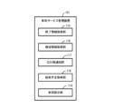
- FIG. 2 is a diagram showing an overview of the vehicle service management device 101 according to the first embodiment.
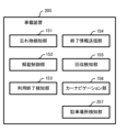
- the vehicle service management device 101 includes a completion information acquisition unit 115, a detection information acquisition unit 116, a lost property notification unit 117, a collection schedule acquisition unit 118, and a vehicle instruction unit 119.
- the end information acquisition unit 115 acquires end-of-use information indicating that the user has ended use of the vehicle.
- the detection information acquisition unit 116 acquires detection information indicating that an item left behind in the vehicle has been detected.
- the lost property notification unit 117 sends a lost property notification indicating that an item has been left behind.
- the collection schedule acquisition unit 118 acquires, in response to the lost item notification, the planned collection time indicating when the user will return to the vehicle's parking location to collect the lost item.
- the vehicle instruction unit 119 transmits unlock control instructions to control the unlocking of the vehicle.
- the unlocking control instructions include instructions to allow the user to unlock the vehicle based on the scheduled collection time.
- This vehicle service management device 101 makes it easy for users to retrieve items left behind in their vehicles.
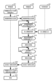
- FIG. 3 is a flowchart showing an example of the first vehicle service management process.
- the end information acquisition unit 115 acquires end-of-use information indicating that the user has ended use of the vehicle (step S132).
- the lost property detection unit 151 detects any lost property in the vehicle (step S133).
- the lost-item notification unit 117 issues a lost-item notification indicating that an item has been left behind (step S136).
- the collection schedule acquisition unit 118 acquires the planned collection time indicating when the user will return to the vehicle's parking location to collect the lost item (step S139).
- the unlocking control unit 152 controls the unlocking of the vehicle (step S127).
- Controlling the unlocking of the vehicle includes allowing the user to unlock the vehicle based on the scheduled collection time.
- This first vehicle service management process makes it easier for users to retrieve items left behind in their vehicles.
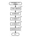
- FIG. 4 is a flowchart showing an example of the second vehicle service management process.
- the end information acquisition unit 115 acquires end-of-use information indicating that the user has ended use of the vehicle (step S132).
- the detection information acquisition unit 116 acquires detection information indicating that an item left behind in the vehicle has been detected (step S135).
- the lost item notification unit 117 sends a lost item notification indicating that an item has been left behind (step S136).
- the collection schedule acquisition unit 118 acquires the planned collection time indicating when the user will return to the vehicle's parking location to collect the lost item (step S139).
- the vehicle instruction unit 119 transmits an unlock control instruction to control the unlocking of the vehicle (step S140).
- the unlocking control instructions include instructions to allow the user to unlock the vehicle based on the scheduled collection time.
- This second vehicle service management process makes it easier for users to retrieve items left behind in their vehicles.
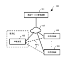
- (detail) 5 is a diagram showing an example of the configuration of the vehicle service management system 100 according to the first embodiment.
- the vehicle service management system 100 is a system for managing vehicle services.
- the vehicle service management system may also be simply referred to as a "management system.”
- a vehicle service is a service that allows multiple users to use a vehicle.
- a vehicle service one or more vehicles are provided with the intention that they will be used by multiple users.
- vehicle services are typically services commonly referred to as car sharing (service) or car sharing (service), but are not limited to this.
- the vehicle service may be, for example, a service for multiple users to use a vehicle owned by a specific organization or individual.
- the vehicle service may be a service for multiple users to use a vehicle owned by a rental car company, or a service for multiple employees to use a vehicle owned by a company, local government, etc.
- the present invention is applicable to various vehicle services such as these.
- vehicle refers to a vehicle used to provide the vehicle service.
- the management system 100 includes a vehicle service management device 101, a plurality of user terminals 103 used by a plurality of users, and an in-vehicle device 105 mounted on a vehicle.
- Vehicle C in the figure is an example of a vehicle.
- the vehicle service management device 101, each of the user terminals 103, and the in-vehicle device 105 are connected to each other via a network NT, and transmit and receive information to each other via the network NT.
- the network NT is a communication line that is wired, wireless, or a combination of these.
- the network NT may include at least a wireless communication line in order to connect, for example, the in-vehicle device 105, the mobile user terminal 103, etc.
- each of the user terminals 103 and the in-vehicle device 105 are connected to each other via short-range wireless communication (NFC) within a predetermined distance, and transmit and receive information to and from each other via the short-range wireless communication (NFC).
- NFC short-range wireless communication
- the user terminals 103 may be one or more user terminals 103.
- the user terminals 103 are not limited to mobile terminals, and may be stationary terminals.
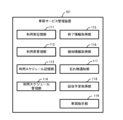
- FIG. 6 is a diagram illustrating an example of a functional configuration of the vehicle service management device 101 according to the first embodiment.
- the vehicle service management device 101 is a device for managing vehicle services.
- the vehicle service management device is also simply referred to as a "management device.”
- the management device 101 functionally includes, for example, a user memory unit 111, a user management unit 112, a usage schedule memory unit 113, a usage schedule management unit 114, an end information acquisition unit 115, a detection information acquisition unit 116, a lost property notification unit 117, a collection schedule acquisition unit 118, and a vehicle instruction unit 119.
- the user storage unit 111 is a storage unit for storing user data 111a.
- the user data 111a is data related to the user. For example, when a user uses a vehicle service, the user is pre-registered in the user data 111a.
- Figure 7 shows an example of user data 111a.
- User data 111a associates, for example, a user ID (identification) and contact information.
- the user ID is information for identifying each user.
- the contact information is information indicating the user's contact information.
- the user data 111a shown in the figure includes data indicating that the contact telephone number for a user with a user ID of "UA" is "090-XXXX-XXXX.” It is preferable that the telephone number be one that allows contact via a terminal carried by the user (such as the user terminal 103).
- user data 111a is not limited to this.
- user data 111a may include one or more of a user ID, a user terminal ID, contact information, the user's name, address, payment information, etc.
- the user terminal ID is information for identifying each user terminal 103.
- the information for identifying a user is not limited to a user terminal ID, and may be one or more pieces of information such as a user terminal ID, contact information, and a user terminal ID.
- the contact information may be one or more pieces of information such as a telephone number, an email address, and an ID in a social networking service (SNS) used by the user.
- SNS social networking service
- the user management unit 112 performs processing for managing users.
- the user management unit 112 manages the user data 111a based on the user information.
- the user information is information about the user, and includes, for example, contact information entered by the user.
- the management of the user data 111a may include one or more of the following: registering a new user in the user data 111a, updating the user data 111a related to an already registered user, etc.
- the usage schedule storage unit 113 is a storage unit for storing usage schedule data 113a.
- the usage schedule data 113a is data that indicates a usage schedule related to a vehicle.
- usage schedule refers to a usage schedule related to a vehicle.
- FIG. 8 shows an example of usage schedule data 113a.
- the usage schedule data 113a associates, for example, a schedule ID, a vehicle ID, a user ID, a planned time of use, a planned location of use, and a usage end flag.
- the schedule ID is information used to identify each usage schedule.
- the vehicle ID is information used to identify the vehicle.
- the user ID corresponds to the user ID included in the user data 111a.
- the user ID can be used to associate the user data 111a with the usage schedule data 113a.
- the planned use time is information that indicates the planned time when the vehicle is to be used.
- the planned use time includes, for example, the planned start time of use and the planned end time of use.
- the planned start time of use is the planned time when the use of the vehicle is to begin.
- the planned end time of use is the planned time when the use of the vehicle is to end. These times are expressed, for example, as a combination of date and time, but are not limited to this.
- the planned location of use is information about the location where the vehicle is planned to be used.
- the planned location of use includes, for example, the planned boarding location and the planned return location.
- the planned boarding location is the location where the vehicle is planned to start being used.
- the planned return location is the location where the vehicle is planned to end being used.
- the planned pick-up location and return location are selected by the user according to his/her preference from multiple locations, such as a parking lot, designated by the vehicle service.
- the usage end flag is a flag that indicates that the usage of the vehicle scheduled in the usage schedule has ended.
- “0" indicates that the usage of the associated vehicle has not yet ended, and "1" is set when the usage has ended.
- the usage schedule data 113a is not limited to this.
- a condition for using a vehicle service may stipulate that the planned boarding location and the planned return location are a common location, and in such a case the usage location information may be a single piece of information indicating the common location.
- the usage end flag is not limited to "0" or "1", and other methods may be used.
- the usage schedule management unit 114 performs processing for managing the usage schedule based on reservation information for a user to reserve a vehicle.
- the usage schedule management unit 114 manages the usage schedule data 113a based on reservation information.
- the reservation information may include one or more of reservation application information, reservation update information, etc.
- Reservation application information is information that allows a user to make a new reservation for a vehicle.
- Reservation update information is information that allows a user to change the details of an existing reservation for a vehicle that has already been reserved.
- the usage schedule management unit 114 generates usage schedule data 113a indicating a new usage schedule based on the reservation application information.
- the schedule registration unit 114a then stores the generated usage schedule data 113a in the usage schedule storage unit 113.
- the usage schedule management unit 114 updates the usage schedule data 113a stored in the usage schedule storage unit 113 based on the reservation update information.
- the end information acquisition unit 115 acquires usage end information.
- the end-of-use information is information indicating that a user will end use of a vehicle.
- the end-of-use information includes, for example, at least one of a user ID and a vehicle ID for identifying the user and the vehicle, respectively.
- the end information acquisition unit 115 When the end information acquisition unit 115 acquires the usage end information, it may set the usage end flag of the usage schedule data 113a related to the acquired usage end information to "1.”
- the detection information acquisition unit 116 acquires detection information.
- the detection information is information indicating that an item left behind in the vehicle has been detected.
- An ETC card is a card used to use the Electronic Toll Collection System (ETC).
- the lost property notification unit 117 issues a lost property notification.
- a lost property notification is a notification that indicates that an item has been left behind in the vehicle.
- the lost-item notification unit 117 issues a lost-item notification when the end-of-use information and detection information are acquired by the end-of-use information acquisition unit 115 and the detection information acquisition unit 116, respectively.
- the lost property notification unit 117 sends a lost property notification to the user terminal 103 of a user who has left an item in a vehicle.
- the user who left an item is, for example, the user who most recently used the vehicle when a lost item was detected in the vehicle.
- Such a user may be identified using the usage end information acquired by the end information acquisition unit 115.
- the scheduled collection acquisition unit 118 acquires the scheduled collection time in response to the lost item notification sent by the lost item notification unit 117.
- the scheduled collection time is information indicating the time when the user who left the item will return to the vehicle return location to collect the lost item.
- the time is expressed using, for example, one or more of a date, time, time period, etc., but is not limited to this.
- the return location is the location where the user returns the vehicle, and is typically the planned return location. However, if the user changes their plans, the return location may be a location different from the planned return location. In this case, the return location may be any of the locations specified by the vehicle service, just like the planned return location.
- the vehicle instruction unit 119 transmits an unlock control instruction to control the unlocking of the vehicle.
- the unlock control instruction is, for example, an instruction to allow a specific user to unlock the vehicle at a specific time.
- Unlock control instructions are sent when a user reserves a vehicle or retrieves lost property.
- an unlocking control instruction in response to a vehicle reservation is an instruction to allow the user who reserved the vehicle to unlock the vehicle from an allowable start time that is determined based on the planned start time of use.
- the allowable start time may be the planned start time of use, or may be a specified time (e.g., 5 minutes) before the planned start time of use.
- an unlock control instruction in response to the collection of a lost item is an instruction to allow the user who left the item in the vehicle to unlock the vehicle from the start of the permission period determined based on the scheduled collection time.
- the start of the permission period may be the scheduled collection time, as described above, or a specified time (e.g., 5 minutes) before the scheduled collection time. Note that if the start of the permission period is a specified time before the scheduled collection time, the specified time may be different or the same for the unlock control instruction in response to the reservation of a vehicle and the unlock control instruction in response to the collection of a lost item.
- FIG. 9 is a diagram illustrating an example of a functional configuration of the user terminal 103 according to embodiment 1.
- Each of the user terminals 103 according to this embodiment is a mobile terminal carried by a user, such as a smartphone or a tablet terminal.
- Each of the user terminals 103 should have similar functions. Therefore, here, the functional configuration will be explained using one of the multiple user terminals 103 as an example.
- the user terminal 103 functionally comprises, for example, a registration unit 131, a reservation unit 132, a personal information output unit 133, a lost property notification acquisition unit 134, and a collection schedule notification unit 135.
- the registration unit 131 transmits user information, for example, based on input from the user.
- the reservation unit 132 generates reservation information based on, for example, user input, and transmits the generated reservation information.
- the personal information output unit 133 When the user performs a specific operation, such as when starting or ending use of a reserved vehicle or retrieving an item left behind in the vehicle, the personal information output unit 133 outputs personal information, for example, using short-range wireless communication (NFC).
- NFC short-range wireless communication
- the personal information is information used to verify that the user is the one who reserved the vehicle, or the user who left something behind in the vehicle.
- the personal information includes, for example, a user ID. Note that the personal information is not limited to this, and may be, for example, a reservation number issued at the time of reservation.
- the personal information output unit 133 when the personal information output unit 133 receives a predetermined operation from the user and when a predetermined location of the user terminal 103 and the in-vehicle device 105 are positioned within a predetermined distance, the personal information output unit 133 performs short-range wireless communication (NFC) with the in-vehicle device 105.
- the personal information output unit 133 transmits personal information to the in-vehicle device 105 using the short-range wireless communication (NFC).
- the lost item notification acquisition unit 134 acquires the lost item notification.
- the collection schedule notification unit 135 transmits the planned collection time based on, for example, input from the user.
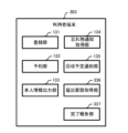
- the in-vehicle device 105 functionally includes, for example, a lost property detection unit 151, an unlocking control unit 152, a use end detection unit 153, an end information transmission unit 154, a collection detection unit 155, and a car navigation unit 156.
- the lost property detection unit 151 detects items left behind in the vehicle.
- the lost property detection unit 151 includes one or more sensors that acquire information for detecting lost property in the vehicle.
- sensors include an ETC (Electronic Toll Collection System) device and a camera.
- An ETC device is a device for using ETC.
- an ETC card is attached to the ETC device.
- the ETC device detects when the ETC card, which is a recording medium, is attached.
- the ETC device then reads the information recorded on the ETC card and uses the read information to carry out processing for using ETC.
- the lost item detection unit 151 may, for example, obtain information from the ETC device indicating that an ETC card is attached to the ETC device, and detect that the ETC card is inside the vehicle as a lost item.
- the ETC device is an example of a device (vehicle installation device) that is installed in a vehicle and is used by connecting a recording medium, a terminal, etc.
- the recording medium, the terminal, etc. are typically owned by the user, and the method of connecting them to the vehicle installation device may be contact between terminals by installation, a wired connection using a cable, or a wireless connection.
- the vehicle installation device may be a card reading device that is attached to a card-type medium such as a membership card or credit card, not limited to an ETC card, and reads information from the card-type medium.
- the vehicle installation device may be a device that is attached to a recording medium such as a USB (Universal Serial Bus) storage or a memory card (e.g., an SD memory card), and reads information from the recording medium.
- a recording medium such as a USB (Universal Serial Bus) storage or a memory card (e.g., an SD memory card)
- the vehicle installation device may be a device that is connected to a terminal such as a smartphone or a tablet terminal by wire or wireless, and operates by transmitting and receiving information between the connected terminal.
- the vehicle installation device is not limited to a device that is installed inside the vehicle, but may also be a device that is installed outside the vehicle, such as an antenna device.
- the lost property detection unit 151 includes a camera
- the camera takes pictures of the inside of the vehicle, for example.
- the lost property detection unit 151 analyzes the images of the inside of the vehicle taken by the camera to detect any lost property inside the vehicle.
- General techniques can be used for image analysis to detect items left behind in vehicles, such as image comparison and machine learning models.
- the lost item detection unit 151 may, for example, compare an image of the interior of the vehicle without any lost items with an image captured by a camera to determine the similarity between the two images, and detect any lost items in the vehicle based on the results of comparing this similarity with a predetermined threshold value.
- the lost item detection unit 151 may detect items left inside the vehicle by, for example, inputting images captured by a camera into a machine learning model that has been trained to detect objects based on input images.
- training the machine learning model for example, training data including training images captured inside the vehicle and correct answer labels indicating lost items contained in the training images may be used.
- a camera may be provided to capture images of the exterior of the vehicle so that the lost item detection unit 151 can detect items attached to the outside of the vehicle.
- the sensor may be a sensor attached inside the dashboard to detect items left inside the dashboard.
- the unlocking control unit 152 controls the unlocking of the vehicle according to the unlocking control instructions.
- the unlocking control unit 152 normally prohibits all users from unlocking the vehicle.
- the unlock control unit 152 When the unlock control unit 152 acquires an unlock control instruction, it allows the vehicle to be unlocked in accordance with the acquired unlock control instruction. If the unlocking of the vehicle is permitted, it unlocks the vehicle when it acquires personal information indicating the user identified by the unlock control instruction.
- the personal information is acquired from the user terminal 103, for example, using short-range wireless communication (NFC).
- NFC short-range wireless communication
- the method of acquiring the personal information is not limited to this, and the personal information may be acquired, for example, by the user inputting the personal information into the in-vehicle device 105.
- the in-vehicle device 105 is provided with an input unit (not shown) for inputting the personal information from outside the vehicle.
- the unlocking control unit 152 continues to unlock the vehicle until the end of vehicle use is detected by the end-of-use detection unit 153 (described later) or the retrieval detection unit 155 detects the retrieval of the left-behind property.
- the end-of-use detection unit 153 detects when a user has finished using a vehicle based on a reservation.
- the usage end detection unit 153 may detect the end of vehicle usage based on a user operation, or by acquiring specific information based on a user operation from the user terminal 103.
- the usage end detection unit 153 may detect the end of vehicle usage by acquiring personal information indicating the user who used the vehicle based on a reservation from the user terminal 103 using short-range wireless communication NFC. Note that the method of detecting the end of vehicle usage is not limited to these.
- the end information transmission unit 154 transmits end-of-use information when the use of the vehicle ends.
- the termination information sending unit 154 may be provided in the user terminal 103 and may send the usage termination information based on a specific operation by the user.
- the collection detection unit 155 detects when an item left behind in a vehicle has been collected.
- the collection detection unit 155 may detect that a lost item has been collected when the lost item detection unit 151 does not detect the lost item. For example, the collection detection unit 155 may detect that a lost item has been collected based on a user's operation, or by acquiring from the user terminal 103 specific information based on a user's operation. For example, the collection detection unit 155 may detect that a lost item has been collected by acquiring personal information indicating the user who left the item from the user terminal 103 using short-range wireless communication NFC. Note that the method of detecting the collection of a lost item is not limited to these.
- the car navigation unit 156 guides the user on the journey of the vehicle C.
- the car navigation unit 156 has at least one of a display function and a voice output function.
- the car navigation unit 156 with a display function may, for example, display on a map the current position of the vehicle C, the positions of facilities, roads, and the route from the current position to the destination.
- the car navigation unit 156 with a voice output function may, for example, output voice to convey various information to the user, such as driving directions.
- Fig. 11 is a diagram showing an example of the physical configuration of the management device 101 according to the first embodiment.
- Fig. 12 is a diagram showing an example of the physical configuration of the user terminal 103 according to the first embodiment.
- Fig. 13 is a diagram showing an example of the physical configuration of the in-vehicle device 105 according to the first embodiment.
- Each of the management device 101, the user terminal 103, and the in-vehicle device 105 has a bus 1010, a processor 1020, a memory 1030, a storage device 1040, a network interface 1050, an input interface 1060, and an output interface 1070.
- Each of the user terminal 103 and the in-vehicle device 105 further has a short-range communication interface 1080.
- the in-vehicle device 105 further has a device connection interface 1090.
- the bus 1010 is a data transmission path for the processor 1020, memory 1030, storage device 1040, network interface 1050, input interface 1060, and output interface 1070 to transmit and receive data to and from each other.
- the method of connecting the processor 1020 and other components to each other is not limited to bus connection.
- the processor 1020 is a processor realized by a CPU (Central Processing Unit) or a GPU (Graphics Processing Unit).
- Memory 1030 is a main storage device realized by a RAM (Random Access Memory) or the like.
- Storage device 1040 is an auxiliary storage device realized by a hard disk drive (HDD), a solid state drive (SSD), a memory card, or a read only memory (ROM).
- Storage device 1040 stores program modules for realizing the functions of the device that includes it.
- Processor 1020 loads each of these program modules into memory 1030 and executes them to realize the function corresponding to that program module.
- the network interface 1050 is an interface for connecting a device equipped with it to the network NT.
- the input interface 1060 is an interface through which the user inputs information.
- the input interface 1060 is composed of, for example, a touch panel, a keyboard, a mouse, etc.
- the output interface 1070 is an interface for presenting information to the user.
- the output interface 1070 is composed of, for example, a liquid crystal panel, an organic EL (Electro-Luminescence) panel, etc.
- the short-range communication interface 1080 is an interface for sending and receiving information using the short-range wireless communication (NFC) and is connected to the bus 1010.
- NFC short-range wireless communication
- the device connection interface 1090 is an interface for transmitting and receiving information to and from other devices, and is connected to the bus 1010.
- the device connection interface 1090 may be an interface that uses either a wired or wireless connection to connect to other devices.
- FIG. 13 shows an example in which a camera 1091, an ETC device 1092, and a lock mechanism unit 1093 are connected to the device connection interface 1090.
- Each of the camera 1091 and the ETC device 1092 is an example of a sensor that constitutes the lost property detection unit 151.
- the lock mechanism unit 1093 is a mechanism for controlling the unlocking and locking of the lock, for example, mechanically or electromagnetically. Note that the method of controlling the lock is not limited to mechanical or electromagnetic methods, and may be changed as appropriate.
- each of the management device 101 and the user terminal 103 may be physically composed of multiple devices.
- each of the multiple devices may physically include the components 1010-1070 shown in Figures 11-12.
- the in-vehicle device 105 may be physically composed of multiple devices.
- each of the multiple devices may physically include the components 1010-1090 shown in Figure 13.
- the management system 100 executes vehicle service management processing.
- This vehicle service processing includes user management processing, usage schedule management processing, usage start processing, and usage end processing.
- the user management process is a process for managing users of a vehicle service.
- the user management process is started when the user terminal 103 accepts a predetermined operation by a user, for example, when a user is newly registered in the user data 111a, when the user data 111a of an already registered user is changed, etc.
- the trigger for starting the user management process is not limited to this.
- the registration unit 131 generates user information based on the user's input (step S101).
- the user information includes information entered by the user, such as contact information. Also, for example, if the user is already registered, the user information further includes the user ID of the user.
- the registration unit 131 transmits the user information generated in step S101 based on the user's instructions (step S102).
- the user management unit 112 acquires the user information sent in step S102 (step S103).
- the user management unit 112 generates user data 111a based on the user information acquired in step S103 (step S104).
- the user management unit 112 When registering a new user, the user management unit 112 automatically generates a user ID, for example, and generates user data 111a including the generated user ID and the acquired contact information. In addition, when updating user data 111a related to an already registered user, user data 111a including the acquired user ID and contact information is generated.
- the user management unit 112 stores the user data 111a generated in step S104 in the user storage unit 111 (step S105), and ends the user management process. This allows the user to be registered.
- the usage schedule management process is a process for managing a usage schedule.
- the usage schedule management process is started, for example, when the user terminal 103 accepts a predetermined operation by a user. Note that the trigger for starting the usage schedule management process is not limited to this.
- the reservation unit 132 generates reservation information based on the user's input (step S111).
- the reservation information may be reservation application information, reservation update information, etc., and may include one or more of the planned time and place of use that the user desires.
- the reservation information may also include the type of vehicle that the user desires to use. Vehicle types include, for example, compact cars, passenger cars, wagons, trucks, etc.
- the reservation unit 132 transmits the reservation information generated in step S111 based on the user's instructions (step S112).
- the usage schedule management unit 114 acquires the reservation information sent in step S112 (step S113).
- the usage schedule management unit 114 determines whether a vehicle can be arranged based on the user's request contained in the reservation information acquired in step S113 (step S114).
- the usage schedule management unit 114 determines whether or not a vehicle that meets the user's requirements can be arranged. In detail, for example, if there is no vehicle available at the planned usage time and location desired by the user due to a prior reservation, the usage schedule management unit 114 determines that a vehicle cannot be arranged. Also, for example, if there is a vehicle, such as vehicle C, available at the planned usage time and location desired by the user, the usage schedule management unit 114 determines that a vehicle can be arranged.
- step S114 If it is determined that a vehicle cannot be arranged (step S114; No), the usage schedule management unit 114 ends the usage schedule management process. If it is determined that a vehicle can be arranged (step S114; Yes), the usage schedule management unit 114 generates usage schedule data 113a based on the reservation information acquired in step S112 (step S115).
- the usage schedule management unit 114 automatically generates a schedule ID and generates usage schedule data 113a including the generated schedule ID.
- This usage schedule data 113a further includes, for example, the user ID, the planned time and place of use included in the reservation application information, and the vehicle ID of the arranged vehicle C.
- the usage schedule management unit 114 acquires usage schedule data 113a including the user ID, schedule ID, etc., included in the reservation update information from the usage schedule storage unit 113.
- the usage schedule management unit 114 changes at least one of the planned usage time, planned usage location, and vehicle ID of the acquired usage schedule data 113a according to the reservation update information, and generates updated usage schedule data 113a.
- the usage schedule management unit 114 stores the usage schedule data 113a generated in step S115 in the usage schedule storage unit 113 (step S116), and ends the usage schedule management process. This allows the user to make a new reservation for a vehicle C that meets his or her needs, or to update an existing reservation to different details.
- (Example of start-of-use process according to the first embodiment) 16 is a diagram showing an example of the flow of the start-of-use process according to the first embodiment.
- the start-of-use process is a process for starting the use of a vehicle based on a reservation made by a user.
- the start-of-use process is started, for example, when it is time to send an unlock control instruction corresponding to the reservation of the vehicle.
- the time to send this unlock control instruction is, for example, a predetermined time (for example, 10 minutes) before the next scheduled start time of use.
- the trigger for starting the start-of-use process is not limited to this.
- the vehicle instruction unit 119 transmits an unlock control instruction according to the vehicle reservation (step S121).
- the unlock control instruction sent in step S121 is an instruction to allow user UA (a specific user) to unlock vehicle C 5 minutes (a specific time) before the planned start time of use "TAS".
- the unlocking control unit 152 acquires the unlocking control instruction sent in step S121 (step S122).
- the unlocking control unit 152 determines whether or not short-range wireless communication NFC has been established between the user terminal 103 and the in-vehicle device 105 (step S123). If short-range wireless communication NFC has not been established (step S123; No), the unlocking control unit 152 waits until short-range wireless communication NFC is established.
- the personal information output unit 133 When short-range wireless communication (NFC) is established with the unlock control unit 152 in response to a specific operation by the user, the personal information output unit 133 outputs personal information (step S124).
- NFC short-range wireless communication
- the personal information output unit 133 performs an operation on the user terminal 103 to output the personal information of the user, and brings the user terminal 103 close to the in-vehicle device 105. This establishes short-range wireless communication (NFC) between the user terminal 103 and the in-vehicle device 105.
- NFC short-range wireless communication
- step S123 If short-range wireless communication NFC is established (step S123; Yes), the unlocking control unit 152 acquires the personal information output in step S124 (step S125).
- the unlocking control unit 152 determines whether the time when the personal information was acquired in step S125 and the user indicated by the personal information satisfy the specific time and user included in the unlocking control instruction acquired in step S122 (step S126).
- the unlocking control unit 152 determines that the specific time and user are satisfied.
- a case in which both are satisfied is, for example, when the time when the personal information was acquired is included in the specific time, and the user indicated by the personal information is a specific user. If at least one of the specific time and user included in the unlocking control instruction is not satisfied, it is determined that the specific time and user are not satisfied.
- step S126 the unlocking control unit 152 executes step S123 again.
- the unlocking control unit 152 may return to step S123 until the planned start time of use "TAS" has passed, or until a predetermined time (e.g., 10 minutes) has passed since the planned start time of use "TAS", or until both the specific time and user are met. Then, if both the specific time and user are not met even after the planned start time of use "TAS" or the predetermined time (e.g., 10 minutes) has passed since the planned start time of use "TAS", the unlocking control unit 152 may, for example, end the start of use process.
- a predetermined time e.g. 10 minutes
- step S126 If it is determined that the specific time and user are met (step S126; Yes), the unlocking control unit 152 unlocks the reserved vehicle C as vehicle unlocking control (step S127), and ends the usage start process.
- the unlocking control unit 152 can allow the user UA to unlock the vehicle C based on the planned start time of use. Then, after the vehicle C is unlocked in step S127, the user UA can use the key to use the vehicle C. For example, the user UA can use the car navigation unit 156 to drive the vehicle C as needed. The user UA can also use the key to lock and unlock the vehicle C as needed.
- Example of usage termination process according to the first embodiment 17 and 18 are diagrams showing an example of the flow of the usage end process according to the first embodiment.
- the usage end process is a process for ending the usage of the vehicle based on the reservation of the user.
- the usage end process is started, for example, when the usage end detection unit 153 detects the end of the usage of the vehicle and the unlock control unit 152 locks the vehicle C. Note that the trigger for starting the usage end process is not limited to this.
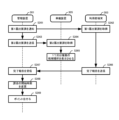
- the end information transmission unit 154 transmits use end information (step S131).
- the end information acquisition unit 115 acquires the usage end information transmitted in step S131 (step S132). At this time, the end information acquisition unit 115 may set the usage end flag associated with the schedule ID "SCA" in the usage schedule data 113a shown in FIG. 8 to "1.”
- the lost property detection unit 151 determines whether or not a lost property has been detected in vehicle C (step S133). If no lost property has been detected (step S133; No), the lost property detection unit 151 ends the usage termination process.
- the lost item detection unit 151 transmits detection information indicating that a lost item has been detected in vehicle C (step S134).
- the detection information acquisition unit 116 acquires the detection information sent in step S134 (step S135).
- the lost item notification unit 117 issues a lost item notification indicating that an item has been left behind in vehicle C (step S136).
- the lost item notification unit 117 refers to the user data 111a to identify the contact information of the user UA who most recently used the vehicle C in which the lost item was detected.
- the lost item notification unit 117 sends a notification to the identified contact information. If the contact information is a telephone number, the lost item notification unit 117 sends a notification by telephone using an automated voice, for example. This allows the lost item notification unit 117 to send a lost item notification when the end of use information is acquired and a lost item is detected.
- the lost item notification is not limited to notification by telephone, but may be notification by email to the user's email address, notification to the SNS used by the user, or notification using any other method.
- the lost item notification acquisition unit 134 acquires the lost item notification made in step S136 (step S137).
- the lost item notification acquisition unit 134 acquires the lost item notification when the user UA answers the phone call. This allows the user UA to know that he or she has left an item in the vehicle C through an automated voice message.
- the collection schedule notification unit 135 transmits the planned collection time based on the input of the user UA in response to the lost property notification obtained in step S137 (step S138).
- the user UA when the lost property notification is made by telephone, the user UA follows the automated voice and inputs the planned collection time using numeric input keys or the like.
- the numeric input keys may be, for example, those provided with a general telephone function for inputting a telephone number.
- the collection schedule notification unit 135 transmits the planned collection time input by the user UA.
- the collection schedule acquisition unit 118 acquires the planned collection time sent in step S138 (step S139).
- the vehicle instruction unit 119 transmits an unlock control instruction corresponding to the collection of the lost property based on the planned collection time acquired in step S139 (step S140).
- the unlocking control instruction sent in step S140 is an instruction to allow the user UA (specific user) who left the property behind to unlock the vehicle C five minutes (specific time) before the specified time of the scheduled collection time.
- the unlocking control unit 152 acquires the unlocking control instruction sent in step S140 (step S141).
- step S126 the unlocking control unit 152 executes step S123 again.
- the unlocking control unit 152 may return to step S123 until the scheduled collection time or a predetermined time (e.g., 10 minutes) has passed since the scheduled collection time, or until both the specific time and user are met. Then, if the scheduled collection time or a predetermined time (e.g., 10 minutes) has passed since the scheduled collection time, and both the specific time and user are not met, the unlocking control unit 152 may, for example, end the usage termination process.
- a predetermined time e.g. 10 minutes
- step S126 If it is determined that the specific time and user conditions are met (step S126; Yes), the unlocking control unit 152 unlocks the vehicle C in which the lost item was detected (step S142).
- the unlocking control unit 152 can allow the user UA to unlock the vehicle C based on the planned collection time.
- the collection detection unit 155 determines whether the item left behind in vehicle C has been collected (step S143). If the collection of the item has not been detected (step S143; No), the collection detection unit 155 repeats step S143 and waits until the item left behind in vehicle C has been collected.
- vehicle C remains unlocked until the retrieval of the lost property is detected, allowing user UA to retrieve the lost property in vehicle C.
- step S143 If retrieval of the lost property is detected (step S143; Yes), the unlocking control unit 152 locks the vehicle C (step S144). As a result, the unlocking control unit 152 prohibits all users from unlocking the vehicle C, and ends the usage termination process.
- the management system 100 includes a completion information acquisition unit 115 , a lost item detection unit 151 , a lost item notification unit 117 , a collection schedule acquisition unit 118 , and an unlocking control unit 152 .
- the end information acquisition unit 115 acquires usage end information indicating that the user has ended use of the vehicle.
- the lost property detection unit 151 detects items left behind in the vehicle.
- the lost property notification unit 117 issues a lost property notification indicating that an item has been left behind.
- the collection schedule acquisition unit 118 in response to the lost item notification, acquires the scheduled collection time indicating when the user will return to the vehicle's parking location to collect the lost item.
- the unlocking control unit 152 controls the unlocking of the vehicle. Controlling the unlocking of the vehicle includes allowing the user to unlock the vehicle based on the scheduled collection time.
- the management system according to the second embodiment includes a management device 201 and an in-vehicle device 205, which replace the management device 101 and the in-vehicle device 105, respectively, according to the first embodiment.
- FIG. 19 is a diagram showing an example of the functional configuration of a management device 201 according to the second embodiment.
- the management device 201 includes, for example, a termination information acquisition unit 215 that replaces the termination information acquisition unit 115 according to the first embodiment.
- the end information acquisition unit 215 acquires the parking location of the vehicle whose use has ended, in addition to the use end information similar to that of the first embodiment.
- the end information acquisition unit 215 determines whether the acquired parking location is the planned return location of the vehicle whose use has ended.
- FIG. 20 is a diagram showing an example of the functional configuration of the in-vehicle device 205 according to the second embodiment.
- the in-vehicle device 205 further includes, for example, a parking location detection unit 257.
- the parking location detection unit 257 detects where the vehicle is parked, for example, when the vehicle is no longer in use and is parked.
- the parking location detection unit 257 detects the location of the parking location using functions such as GPS (Global Positioning System) and Wi-Fi.
- Parking a vehicle means, for example, stopping the vehicle and stopping the operation of the vehicle's drive source (e.g., engine, motor).
- the vehicle service management executed by the management system according to the second embodiment includes a usage termination process that is partially different from that of the first embodiment.
- the processing included in the usage termination process that differs from that of the first embodiment will be mainly described.
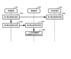
- Example of usage termination process according to the second embodiment 21 is a diagram showing an example of the flow of a usage termination process according to embodiment 2.
- the parking location detection unit 257 detects the parking location of the vehicle C (step S245) and transmits the detected parking location.
- the end information acquisition unit 215 acquires the parking location detected in step S245 (step S246).
- the end information acquisition unit 215 determines whether the parking location acquired in step S246 is the planned return location of vehicle C (step S247).
- the termination information acquisition unit 215 terminates the usage termination process.
- step S135 is executed as in embodiment 1. Note that in this embodiment, instead of when step S132 is executed, when the parking location is the planned return location of vehicle C (step S247; Yes), the end information acquisition unit 115 may set the usage end flag associated with the schedule ID "SCA" to "1.”
- the lost property notification unit 117 issues a lost property notification indicating that an item has been left behind in vehicle C (step S136), as in the first embodiment. Therefore, in this embodiment, the lost property notification is sent when the usage end information is acquired, a lost item is detected, and the parking location is a predetermined location (e.g., a return location).
- the management system includes the parking location detection unit 257.
- the parking location detection unit 257 detects the parking location of the vehicle.
- the lost property notification is performed when the usage end information is acquired, a lost property is detected, and the parking location is a predetermined location.
- a lost item notification is sent. This allows the user to easily retrieve the lost item directly from the vehicle by returning to the parking spot to retrieve the lost item. This makes it easy for the user to retrieve the lost item if they leave it in the vehicle.
- the management system according to the third embodiment includes a management device 301, a user terminal 303, and an in-vehicle device 305, which replace the management device 101, the user terminal 103, and the in-vehicle device 105, respectively, of the first embodiment.
- FIG. 22 is a diagram showing an example of the functional configuration of a management device 301 according to embodiment 3.
- the management device 301 further includes, for example, a lost property handling unit 320, a schedule change prohibition unit 321, a billing unit 322, a notification request unit 323, and a point allocation unit 324.
- the lost property handling unit 320 controls the execution of different lost property handling processes based on the planned start time of the next use and the planned time of collection of the lost property.
- the next planned start time of use is the planned start time of use for the next user.
- the next user is the user who plans to use the vehicle in which the lost item was left (i.e., who has made a reservation for such use) after the user who left the item behind.
- the lost property handling unit 320 performs control to execute different first and second lost property handling processes based on whether the planned collection time is before the next planned start time of use. Details of the first and second lost property handling processes will be described later.
- the lost property handling unit 320 may also control the execution of different lost property handling processes based on, for example, whether the time difference between the scheduled collection time and the scheduled start time of the next use is within a specified time.
- the schedule change prohibition unit 321 prohibits changes to the usage schedule related to the vehicle. For example, the schedule change prohibition unit 321 prohibits the usage schedule management unit 114 from changing the usage schedule data 113a based on reservation information. Furthermore, the schedule change prohibition unit 321 lifts the prohibition on changes to the usage schedule when a predetermined condition is met (for example, when a left-behind item is retrieved).
- the changes to the usage schedule that are prohibited by the schedule change prohibition unit 321 are changes to the usage schedule data 113a based on at least one of reservation application information, reservation update information, etc. That is, for example, the schedule change prohibition unit 321 prohibits either or both of a new reservation based on reservation information and a change to the contents of an existing reservation based on reservation update information.
- the billing unit 322 determines the usage fee for the user.
- the usage fee is the fee for using the vehicle service.
- the billing unit 322 may determine an additional fee.
- the billing unit 322 may determine billing conditions for determining the fee for vehicle use. In this case, the billing unit 322 may determine the fee for vehicle use in accordance with the billing conditions. For example, if the fee for vehicle use is determined according to the duration of vehicle use, the billing conditions are the start time of billing and the end time of billing.
- the start time of billing is usually, for example, the time when vehicle use begins.
- the end time of billing is usually, for example, the time when vehicle use ends.
- the notification request unit 323 requests that the item be returned to a predetermined location.
- the predetermined location is, for example, a location where lost items are collected (a lost item collection location), and in detail, for example, a police station or a police box, but is not limited to these.
- FIG. 23 is a diagram showing an example of the functional configuration of the notification request unit 323 according to the third embodiment.
- the notification request unit 323 includes, for example, a notification request notification unit 323a, a notification request transmission unit 323b, and a completion report acquisition unit 323c.
- the report request notification unit 323a notifies the next user of the first report request to return the lost item to a predetermined location.
- the first report request is information indicating a request to return the lost item to a predetermined location.
- the report request notification unit 323a notifies the user terminal 103 of the first report request.
- the notification request sending unit 323b sends a second notification request to present one or more candidate locations for the predetermined location to the next user.
- the second notification request is information indicating a request to present one or more candidate locations for the predetermined location to the next user.
- the completion report acquisition unit 323c acquires a completion report from the next user indicating that the lost item has been reported.
- the point allocating unit 324 determines points to be allocated to the user. For example, the point allocating unit 324 determines points to be allocated to the user according to various predetermined conditions. The points are points for providing the user with benefits that can be used for vehicle services, etc., according to, for example, the accumulated amount of points. The points may be managed by the management device 301 by storing data including, for example, the current points.
- the points allocating unit 324 determines the number of points to be awarded to the next user for returning the lost item.
- FIG. 24 is a diagram showing an example of the functional configuration of a user terminal 303 according to the third embodiment.
- the user terminal 303 further includes, for example, a notification request acquisition unit 336 and a completion report unit 337.
- the notification request acquisition unit 336 acquires the first notification request. In response to the acquired first notification request, the notification request acquisition unit 336 notifies the user to report the item left in the vehicle to a predetermined location.
- the completion report unit 337 sends a completion report based on, for example, a specified operation by the user.
- FIG. 25 is a diagram showing an example of the functional configuration of the in-vehicle device 305 according to the third embodiment.
- the in-vehicle device 305 functionally includes, for example, a collection completion notification unit 358 and a notification location presentation control unit 359.
- the collection completion notification unit 358 issues a collection completion notification.
- the collection completion notification is a notification indicating that an item left behind in a vehicle has been collected. For example, when the collection detection unit 155 detects that an item left behind in a vehicle has been collected, the collection completion notification unit 358 issues a collection completion notification.
- the notification location presentation control unit 359 acquires a second notification request. In response to the acquired second notification request, the notification location presentation control unit 359 presents one or more candidate locations for a predetermined location.
- the candidate locations are, for example, lost property collection locations (e.g., police stations, police boxes, etc.) that are close to (located within a predetermined distance from) the current location when the vehicle in which the lost property was left is first used.
- the vehicle service management executed by the management system according to the second embodiment includes a usage termination process that is partially different from that of the first embodiment.
- the processing included in the usage termination process that differs from that of the first embodiment will be mainly described.
- FIG. 26 is a diagram showing an example of the flow of the usage termination process according to the third embodiment.
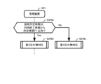
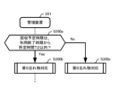
- the lost property management unit 320 determines whether the planned collection time is before the next planned start time of use (step S348).
- the lost property response unit 320 controls to execute the first lost property response process (step S349).
- the lost property response unit 320 controls the execution of the second lost property response process (step S350).
- FIG. 27 is a diagram showing an example of the flow of the first lost property handling process (step S349) in embodiment 3.
- the lost property unit 320 determines whether the planned collection time is within a predetermined time T1 (e.g., 1 hour) from the end of use (step S349a).
- a predetermined time T1 e.g., 1 hour
- the lost property response unit 320 identifies the end of use time based on the time when the end of use information was acquired in step S132.
- the lost property response unit 320 determines whether the planned collection time is within a predetermined time T1 from the end of use time based on the identified end of use time and the planned collection time acquired in step S139.
- step S349a If the planned collection time is within the specified time T1 from the end of use (step S349a; Yes), the lost property response unit 320 controls to execute the third lost property response process (step S349b).
- step S349a If the planned collection time is not within the specified time T1 from the end of use (step S349a; No), the lost property response unit 320 controls to execute the fourth lost property response process (step S349c).
- FIG. 28 is a diagram showing an example of the flow of the third lost property handling process (step S349b) according to the third embodiment.
- the schedule change prohibition unit 321 prohibits changes to the usage schedule for the vehicle (step S351). This makes it possible to prevent the next user from using the vehicle with items left behind in the vehicle.
- Vehicles for which changes to the usage schedule are prohibited are vehicles in which lost property has been left behind.
- step S352 the collection completion notification unit 358 issues a collection completion notification (step S352).
- the schedule change prohibition unit 321 receives the collection completion notification sent in step S352 (step S353).
- the schedule change prohibition unit 321 cancels the change to the usage schedule prohibited in step S351 (step S354). This allows the user to reserve and use the vehicle after the item left in the vehicle has been collected.
- FIG. 29 is a diagram showing an example of the flow of the fourth lost-item handling process (step S349c) according to embodiment 3.
- the fourth lost-item handling process (step S349c) includes step S355 in addition to the processes included in the third lost-item handling process (step S349b).
- the billing unit 322 determines the additional fee associated with prohibiting changes to the vehicle usage schedule to retrieve the lost item (step S355).
- the additional fee is charged to users who leave items behind in the vehicle. This at least reduces the loss to the vehicle service provider that would have been incurred by prohibiting changes to the vehicle usage schedule beyond the specified time T1.
- FIG. 30 is a diagram showing an example of the flow of the second lost property handling process (step S350) in embodiment 3.
- the lost property unit 320 determines whether the planned collection time is within a predetermined time T2 (e.g., 1 hour) from the end of use (step S350a).
- a predetermined time T2 e.g. 1 hour
- the lost property response unit 320 identifies the end of use time based on the time when the end of use information was acquired in step S132.
- the lost property response unit 320 determines whether the planned collection time is within a predetermined time T2 from the end of use time based on the identified end of use time and the planned collection time acquired in step S139.
- step S350a If the planned collection time is within the specified time T2 from the end of use (step S350a; Yes), the lost property response unit 320 controls to execute the fifth lost property response process (step S350b).
- step S350a If the planned collection time is not within the specified time T2 from the end of use (step S350a; No), the lost property response unit 320 controls the execution of the sixth lost property response process (step S350c).
- FIG. 31 is a diagram showing an example of the flow of the fifth lost property handling process (step S350b) according to the third embodiment.
- the notification request notification unit 323a notifies the user terminal 103 of the next user (next user) who will use the vehicle in which the lost item was left, of the first notification request (step S361).
- the notification request acquisition unit 336 acquires the first notification request notified in step S361 (step S362). This notification may be made using the contact information of the next user contained in the user data 111a. If the contact information is a telephone number, this notification may be made, for example, by an automated voice message.
- the notification request sending unit 323b sends a second notification request to the in-vehicle device 305 of the vehicle where the lost item was left (step S363).
- the notification location presentation control unit 359 acquires the second notification request sent in step S363 (step S364).
- the notification location presentation control unit 359 causes, for example, the car navigation unit 156 to present one or more candidate locations for the predetermined location (step S365).
- the next user can then follow the directions of the car navigation unit 156, which uses a map, audio, etc., to return the lost item to a convenient police station or other location.
- the map in this case should preferably show one or more candidate locations, and a route from the vehicle's current position to at least one or more candidate locations.
- the completion report unit 337 sends a completion report (step S366).
- the completion report acquisition unit 323c acquires the completion report sent in step S366 (step S367).
- the billing unit 322 changes the start time of billing (step S368). This means that the next user will not be billed for the time it takes to report the lost item. This can encourage the next user to report the lost item.
- the point allocating unit 324 awards points to the next user for reporting the lost item (step S369). This makes it possible to award a reward for reporting the lost item. This makes it possible to encourage the next user to report the lost item, thereby improving the possibility that the lost item will be safely returned to the user.
- the point allocating unit 324 may determine the points to be awarded to the next user for reporting a lost item if the frequency at which the next user reports a lost item (the number of times the user reports a lost item within a specified period) is equal to or less than a specified value (e.g., three times a month) in step S369.
- a specified value e.g., three times a month
- FIG. 32 is a diagram showing an example of the flow of the sixth lost-item handling process (step S350c) according to embodiment 3.
- the sixth lost-item handling process is similar to the fifth lost-item handling process (step S350b) except that it does not include steps S366 to S369.
- step S350c When the sixth lost property handling process (step S350c) is executed, a time longer than the predetermined time T2 has passed since the end of use. Therefore, in the sixth lost property handling process (step S350c), a request may be made in steps S361 and S363 to report the lost property immediately. In this case, for example, in step S362, the next user may be notified by a voice or other means to report the property quickly. Also, for example, in step S364, the car navigation unit 156 may be caused to guide the next user to report the property to the nearest (for example, nearest) police station as close as possible to the current location of the vehicle used by the next user.
- the nearest for example, nearest
- the management system includes the lost property handling unit 320.
- the lost property handling unit 320 controls the execution of different lost property handling processes based on the planned start time of use and the planned collection time of the next user who is scheduled to use the vehicle.
- the management system includes a schedule change prohibition unit 321 that prohibits changes to the vehicle usage schedule.
- prohibiting changes to the usage schedule is performed when the planned collection time is before the planned start time of use of the next user who is scheduled to use the vehicle.
- the prohibition on changing the usage schedule is lifted when the lost property is retrieved.
- the vehicle can be made available for use by other users. This makes it possible to reduce any decline in the convenience of the vehicle service.
- the management system includes a billing unit 322 that determines the usage fee for the user. Determining the usage fee includes determining an additional fee for the user based on the collection time, which is the time when the lost property is collected.
- the management system includes a notification request unit 323 that requests the next user to return the lost item to a predetermined location.
- the notification request unit 323 notifies the next user of a first notification request indicating a request to report the lost item.
- the notification request unit 323 transmits a second notification request indicating a request to present one or more candidate locations for a predetermined location to the next user.
- the notification request unit 323 obtains a completion report from the next user indicating that the lost item has been turned in.
- the management system further includes a point allocating unit 324 that determines points to be awarded to the next user for turning in the lost item.
- the points to be awarded to the next user for turning in a lost item are determined.
- the management system according to the fourth embodiment includes a management device 401 and a user terminal 403, which replace the management device 301 and the user terminal 303, respectively, of the third embodiment.
- FIG. 33 is a diagram showing an example of the functional configuration of a management device 401 according to embodiment 4.
- the management device 401 further includes, for example, a communication unit 425.
- the communication unit 425 performs communication processing.
- the communication processing is processing for communication between the vehicle user and the next user who is scheduled to use the vehicle.
- the communication processing is executed, for example, when the planned collection time is after the planned start time of use of the next user, but the conditions for executing the communication processing are not limited to this.
- FIG. 34 is a diagram showing an example of the functional configuration of the communication unit 425 according to the fourth embodiment.
- the communication unit 425 includes, for example, a delay request unit 425a, a response acquisition unit 425b, and a response response unit 425c.
- the delay request unit 425a notifies the next user of the delay request.
- the delay request is information indicating a request to delay the planned start time of use for the next user.
- the response acquisition unit 425b acquires the next user's response to the delay request.
- the response response unit 425c controls to execute different response response processes depending on the response acquired by the response acquisition unit 425b. For example, the response response unit 425c controls to execute different first and second response response processes based on whether the next user accepts the delay request.
- FIG. 35 is a diagram showing an example of the functional configuration of a user terminal 403 according to embodiment 4.
- the user terminal 403 further includes, for example, a delay request acquisition unit 438 and a response unit 439.
- the delay request acquisition unit 438 acquires a delay request.
- the response unit 439 transmits the next user's response to the delay request acquired by the delay request acquisition unit 438.
- the vehicle service management executed by the management system according to the fourth embodiment includes a fifth lost-item handling process that is partially different from the fifth lost-item handling process (step S350b) according to the third embodiment.
- the fifth lost-item handling process will be mainly described with respect to the parts that are different from the third embodiment.
- FIG. 36 is a diagram showing an example of the flow of the fifth lost property handling process according to the fourth embodiment.
- the delay request unit 425a notifies the next user of the delay request (step S471).
- the delay request acquisition unit 438 acquires the delay request notified in step S471 (step S472). This notification may be made using the contact information of the next user included in the user data 111a. If the contact information is a telephone number, this notification may be made by, for example, an automated voice message.
- the delay request may include, for example, delaying the scheduled start time of the next user's use to a specified time (e.g., 15 minutes) after the scheduled collection time.
- the delay request may include, for example, delaying the scheduled start time of the next user to a specified time (e.g., 15 minutes) after the scheduled collection time.
- the response unit 439 transmits the next user's response to the delay request (step S473).
- the next user follows the automated voice and inputs a response using numeric input keys or the like.
- the numeric input keys may be, for example, those provided in a general telephone function for inputting a telephone number.
- the response unit 439 transmits the response input by the next user.
- the response may include whether or not to accept the request for a delay.
- the response may include whether or not to accept that the planned start time of the next user's use is delayed to a predetermined time after the planned collection time.
- the answer acquisition unit 425b acquires the answer of the next user sent in step S473 (step S474).
- the response response unit 425c determines whether the next user has accepted the delay request based on the response obtained in step S474 (step S475).
- step S475 If the delay request has been accepted (step S475; Yes), the response response unit 425c controls to execute the first response response process (step S476). If the delay request has not been accepted (step S475; No), the response response unit 425c controls to execute the second response response process (step S477).
- the second response process (step S477) may be similar to the fifth lost-item process (step S350b) according to the third embodiment (see FIG. 31). Therefore, the first response process (step S476) according to this embodiment will be described below with reference to the figure.
- FIG. 37 is a diagram showing an example of the flow of the first response process (step S476) in embodiment 4.
- the usage schedule management unit 114 changes the usage schedule of the next user (step S481).
- the usage schedule management unit 114 changes the planned start time of usage for the next user's usage schedule included in the usage schedule data 113a to a time a predetermined time (e.g., 15 minutes) after the planned collection time.
- a predetermined time e.g. 15 minutes
- the vehicle unlocking control is controlled so that unlocking of the vehicle by the next user is permitted based on the changed scheduled start time of use. For example, unlocking of the vehicle by the next user is permitted from the changed scheduled start time of use or a specified time (e.g., 5 minutes) before that time.
- a specified time interval can be left between the scheduled collection time and the scheduled start time of the next user's use. This reduces the possibility of trouble occurring due to contact between a user who left something behind in a vehicle and the next user of that vehicle.
- Step S140 is executed.
- the point allocating unit 324 awards points to the next user for accepting the delay request (step S482).
- the point allocating unit 324 may determine the points to be awarded to the next user for accepting the delay request if the frequency with which the next user accepts the delay request in step S372 (the number of times the next user delivers within a specified period) is equal to or less than a specified value (e.g., three times a month).
- a specified value e.g., three times a month.
- the management system further includes a communication unit 425 that performs communication processing for communication between a vehicle user and a next user who is scheduled to use the vehicle next.
- the contact process is performed when the planned collection date is after the planned start date of the next user.
- the communication unit 425 includes a delay request unit 425a, a response acquisition unit 425b, and a response handling unit 425c.
- the delay request unit 425a notifies the next user of a delay request to delay the next user's planned start time of use.
- the response acquisition unit 425b acquires the next user's response to the delay request.
- the response handling unit 425c performs control to execute different response handling processes depending on the acquired response.
- the management system includes a usage schedule management unit 114 that updates the usage schedule for the vehicle. Updating the usage schedule includes changing the planned start time of the next user to a predetermined time after the planned collection time when the response includes acceptance of the delay request. Furthermore, controlling the unlocking of the vehicle includes controlling so as to allow the next user to unlock the vehicle based on the changed planned start time of use.
- An end information acquisition means for acquiring end information indicating that a user has ended use of a vehicle;
- a left-behind detection means for detecting an item left behind in the vehicle;
- a lost property notification means for issuing a lost property notification indicating that the item has been left behind when the usage end information is acquired and the item has been detected;
- a collection schedule acquiring means for acquiring a collection schedule indicating a time when the user will return to the parking location of the vehicle to collect the left-behind item in response to the lost-behind item notification;
- an unlocking control means for controlling unlocking of the vehicle, A vehicle service management system, wherein controlling the unlocking of the vehicle includes allowing the user to unlock the vehicle based on the scheduled collection time.
- the vehicle further includes a parking location detection means for detecting a parking location of the vehicle when the vehicle is parked; 2.
- 3. The vehicle service management system according to 1. or 2., further comprising a lost property handling means for controlling execution of different lost property handling processes based on a planned start time of a next user who is scheduled to use the vehicle next and the planned collection time.
- 4. The vehicle service management system according to any one of 1. to 3., further comprising a schedule change prohibition unit that prohibits changes to a usage schedule relating to the vehicle. 5.
- the vehicle service management system according to 4., wherein prohibiting the change of the usage schedule is executed when the planned collection time is before a planned start time of usage of a next user who is scheduled to use the vehicle next. 6.
- a billing management unit is further provided to determine the usage fee of the user, 7.
- the vehicle service management system according to any one of 1.
- the communication means is: a delay request means for notifying the next user of a delay request for delaying a scheduled start time of the next user; a response acquisition means for acquiring a response of the next user to the delay request; and a response handling means for controlling execution of different response handling processes depending on the acquired response.
- a usage schedule management unit is further provided for updating a usage schedule relating to the vehicle, updating the usage schedule includes, when the response includes acceptance of the delay request, changing the scheduled start time of use of the next user to a time after the scheduled collection time by a predetermined time; 11.
- controlling the unlocking of the vehicle includes controlling the unlocking of the vehicle to be permitted by the next user based on the changed scheduled start date of use.
- 12. The vehicle service management system according to any one of 1. to 11., further comprising a notification requesting means for requesting the next user to return the lost item to a predetermined location.
- the notification request means is a notification request notifying means for notifying the next user of a first notification request indicating a request to report the lost property; a notification location presentation control means for transmitting a second notification request indicating a request to present one or more candidate locations for the predetermined location to the next user; a completion report acquisition means for acquiring a completion report from the next user indicating that the lost item has been returned, 13.
- determining of the points includes determining the points to be awarded to the next user for reporting the lost item when the number of times the next user has reported the lost item within a predetermined period is equal to or less than a predetermined value.
- An end information acquisition means for acquiring end information indicating that a user has ended use of the vehicle; a detection information acquiring means for acquiring detection information indicating that an item left behind in the vehicle has been detected; a lost property notification means for issuing a lost property notification indicating that the item has been left behind when the usage end information and the detection information are both acquired; a collection schedule acquiring means for acquiring a collection schedule indicating a time when the user will return to the parking location of the vehicle to collect the left-behind item in response to the lost-behind item notification; a vehicle instruction means for transmitting an unlock control instruction for controlling unlocking of the vehicle, The unlocking control instruction includes an instruction to allow the user to unlock the vehicle based on the scheduled collection time. 16.
- One or more computers Acquire end-of-use information indicating that the user will end use of the vehicle; Detecting items left behind in the vehicle; When the usage end information is acquired and the left-behind property is detected, a lost property notification is issued to indicate that the left-behind property has been found; In response to the notification of the lost property, a planned collection time is obtained that indicates a time when the user will return to the parking location of the vehicle to collect the lost property; controlling the unlocking of the vehicle; The vehicle service management method, wherein controlling the unlocking of the vehicle includes allowing the user to unlock the vehicle based on the scheduled collection time. 17. The method further includes detecting a parking location of the vehicle when the vehicle is parked; 17.
- the vehicle service management method according to claim 16, wherein the notification of the lost item is performed when the usage end information is acquired, the lost item is detected, and the parking location is a predetermined location.
- the vehicle service management method according to 16. or 17. further comprising controlling to execute different lost property handling processes based on a planned start time of a next user who is scheduled to use the vehicle next and the planned collection time.
- the vehicle service management method according to any one of 16. to 18., further comprising prohibiting a change in a usage schedule relating to the vehicle.
- the method further includes determining a usage fee for the user, 22.
- the vehicle service management method according to any one of 19. to 21., wherein determining the usage fee includes determining an additional fee for the user based on a collection time, which is a time when the lost item is collected.
- 23. The vehicle service management method according to any one of 16. to 22., further comprising performing a contact process for contacting a user of the vehicle and a next user who is scheduled to use the vehicle next. 24.
- the vehicle service management method according to 23., wherein the contact process is performed when the scheduled collection time is after a scheduled start time of use of the next user. 25.
- the contact process is notifying the next user of a delay request to delay the scheduled start time of the next user's use; Obtaining a response from the next user to the delay request; 25.
- the method further comprising updating a usage schedule for the vehicle; updating the usage schedule includes, when the response includes acceptance of the delay request, changing the scheduled start time of use of the next user to a time after the scheduled collection time by a predetermined time; 25.
- controlling the unlocking of the vehicle includes controlling the unlocking of the vehicle to be permitted by the next user based on the changed scheduled start date of use.
- the vehicle service management method includes: 28. The vehicle service management method according to claim 27, further comprising, when the completion report is obtained, determining points to be awarded to the next user for turning in the lost item. 29.
- the vehicle service management method further comprising determining the points to be awarded to the next user for reporting the lost item when the number of times the next user has reported the lost item within a predetermined period is equal to or less than a predetermined value.
- determining the points to be awarded to the next user for reporting the lost item when the number of times the next user has reported the lost item within a predetermined period is equal to or less than a predetermined value.
- Vehicle service management system 101, 201, 301, 401 Vehicle service management device (management device) 103, 303, 403 User terminal 105, 205, 305 In-vehicle device 111 User storage unit 111a User data 112 User management unit 113 Usage schedule storage unit 113a Usage schedule data 114 Usage schedule management unit 114a Schedule registration unit 115, 215 End information acquisition unit 116 Detection information acquisition unit 117 Lost property notification unit 118 Collection schedule acquisition unit 119 Vehicle instruction unit 131 Registration unit 132 Reservation unit 133 Personal information output unit 134 Lost property notification acquisition unit 135 Collection schedule notification unit 151 Lost property detection unit 152 Unlock control unit 153 Usage end detection unit 154 End information transmission unit 155 Collection detection unit 156 Car navigation unit 257 Parking location detection unit 320 Lost property response unit 321 Schedule change prohibition unit 322 Billing unit 323 Notification request section 323a Notification request section 323b Notification request transmission section 323c Completion report acquisition section 324 Point giving section 336 Notification request acquisition
Landscapes
- Business, Economics & Management (AREA)
- Accounting & Taxation (AREA)
- Finance (AREA)
- Engineering & Computer Science (AREA)
- Strategic Management (AREA)
- Development Economics (AREA)
- General Business, Economics & Management (AREA)
- Physics & Mathematics (AREA)
- Marketing (AREA)
- General Physics & Mathematics (AREA)
- Economics (AREA)
- Theoretical Computer Science (AREA)
- Mechanical Engineering (AREA)
- Entrepreneurship & Innovation (AREA)
- Game Theory and Decision Science (AREA)
- Traffic Control Systems (AREA)
Abstract
Description
利用者が車両の利用を終了することを示す利用終了情報を取得する終了情報取得手段と、
前記車両における忘れ物を検知する忘れ物検知手段と、
前記利用終了情報が取得され、かつ、前記忘れ物が検知された場合に、前記忘れ物があることを示す忘れ物通知を行う忘れ物通知手段と、
前記忘れ物通知に対する応答として、前記忘れ物を回収するために前記利用者が前記車両の駐車場所へ戻る時期を示す回収予定時期を取得する回収予定取得手段と、
前記車両の解錠を制御する解錠制御手段とを備え、
前記車両の解錠を制御することは、前記回収予定時期に基づいて、前記利用者による前記車両の解錠を許容することを含む
車両サービス管理システムが提供される。
利用者が車両の利用を終了することを示す利用終了情報を取得する終了情報取得手段と、
前記車両に忘れ物が検知されたことを示す検知情報を取得する検知情報取得手段と、
前記利用終了情報が取得され、かつ、前記検知情報が取得された場合に、前記忘れ物があることを示す忘れ物通知を行う忘れ物通知手段と、
前記忘れ物通知に対する応答として、前記忘れ物を回収するために前記利用者が前記車両の駐車場所へ戻る時期を示す回収予定時期を取得する回収予定取得手段と、
前記車両の解錠を制御するための解錠制御指示を送信する車両指示手段とを備え、
前記解錠制御指示は、前記回収予定時期に基づいて、前記利用者による前記車両の解錠を許容させるための指示を含む
車両サービス管理装置が提供される。
1つ以上のコンピュータが、
利用者が車両の利用を終了することを示す利用終了情報を取得し、
前記車両における忘れ物を検知し、
前記利用終了情報が取得され、かつ、前記忘れ物が検知された場合に、前記忘れ物があることを示す忘れ物通知を行い、
前記忘れ物通知に対する応答として、前記忘れ物を回収するために前記利用者が前記車両の駐車場所へ戻る時期を示す回収予定時期を取得し、
前記車両の解錠を制御することを含み、
前記車両の解錠を制御することは、前記回収予定時期に基づいて、前記利用者による前記車両の解錠を許容することを含む
車両サービス管理方法が提供される。
1つ以上のコンピュータに、
利用者が車両の利用を終了することを示す利用終了情報を取得し、
前記車両における忘れ物を検知し、
前記利用終了情報が取得され、かつ、前記忘れ物が検知された場合に、前記忘れ物があることを示す忘れ物通知を行い、
前記忘れ物通知に対する応答として、前記忘れ物を回収するために前記利用者が前記車両の駐車場所へ戻る時期を示す回収予定時期を取得し、
前記車両の解錠を制御することを実行させ、
前記車両の解錠を制御することは、前記回収予定時期に基づいて、前記利用者による前記車両の解錠を許容することを含む
ためのプログラムが記録された記録媒体が提供される。
(概要)
図1は、実施形態1に係る車両サービス管理システム100の概要を示す図である。車両サービス管理システム100は、終了情報取得部115、忘れ物検知部151、忘れ物通知部117、回収予定取得部118及び解錠制御部152を備える。
図5は、実施形態1に係る車両サービス管理システム100の構成例を示す図である。車両サービス管理システム100は、車両サービスを管理するためのシステムである。以下では、車両サービス管理システムを、単に「管理システム」とも称する。
図6は、実施形態1に係る車両サービス管理装置101の機能的な構成例を示す図である。車両サービス管理装置101は、車両サービスを管理するための装置である。以下では、車両サービス管理装置を、単に「管理装置」とも称する。
利用者管理部112は、利用者を管理するための処理を行う。
利用スケジュール管理部114は、利用者が車両を予約するための予約情報に基づいて、利用スケジュールを管理するための処理を行う。
図9は、実施形態1に係る利用者端末103の機能的な構成例を示す図である。本実施形態に係る利用者端末103の各々は、利用者が所持するモバイル型の端末であり、例えばスマートホフォン、タブレット端末などである。
図10は、実施形態1に係る車載装置105の機能的な構成例を示す図である。車載装置105は、機能的に例えば、忘れ物検知部151と、解錠制御部152と、利用終了検知部153と、終了情報送信部154と、回収検知部155と、カーナビゲーション部156とを備える。
図11は、実施形態1に係る管理装置101の物理的な構成例を示す図である。図12は、実施形態1に係る利用者端末103の物理的な構成例を示す図である。図13は、実施形態1に係る車載装置105の物理的な構成例を示す図である。
図14は、実施形態1に係る利用者管理処理の流れの例を示す図である。利用者管理処理は、車両サービスの利用者を管理するための処理である。利用者管理処理は、例えば、利用者を利用者データ111aに新規登録する場合、既に登録された利用者の利用者データ111aを変更する場合などに、利用者端末103が利用者による所定操作を受け付けると開始される。なお、利用者管理処理を開始するトリガは、これに限られない。
図15は、実施形態1に係る利用スケジュール管理処理の流れの例を示す図である。利用スケジュール管理処理は、利用スケジュールを管理するための処理である。利用スケジュール管理処理は、例えば、利用者端末103が利用者による所定操作を受け付けると開始される。なお、利用スケジュール管理処理を開始するトリガは、これに限られない。
図16は、実施形態1に係る利用開始処理の流れの例を示す図である。利用開始処理は、利用者の予約に基づいて車両の利用を開始するための処理である。利用開始処理は、例えば、車両の予約に応じた解錠制御指示を送信する時期になると開始される。この解錠制御指示を送信する時期は、例えば直近の利用開始予定時期より所定時間(例えば、10分)前である。なお、利用開始処理を開始するトリガは、これに限られない。
図17及び18は、実施形態1に係る利用終了処理の流れの例を示す図である。利用終了処理は、利用者の予約に基づく車両の利用を終了するための処理である。利用終了処理は、例えば、利用終了検知部153が車両の利用終了を検知されて、解錠制御部152が車両Cを施錠すると開始される。なお、利用終了処理を開始するトリガは、これに限られない。
以上、本実施形態によれば、管理システム100は、終了情報取得部115、忘れ物検知部151、忘れ物通知部117、回収予定取得部118及び解錠制御部152を備える。
本実施形態では、説明を簡潔にするため、実施形態1と重複する説明は適宜省略し、実施形態1と異なる構成について主に説明する。
図21は、実施形態2に係る利用終了処理の流れの例を示す図である。実施形態2に係る利用終了処理では、ステップS131に続けて、駐車場所検知部257は、車両Cの駐車場所を検知し(ステップS245)、検知した駐車場所を送信する。
以上、本実施形態によれば、管理システムは、駐車場所検知部257を備える。駐車場所検知部257は、車両が駐車した場合に当該車両の駐車場所を検知する。忘れ物通知は、利用終了情報が取得され、忘れ物が検知され、かつ、駐車場所が予め定められた場所である場合に、行われる。
本実施形態では、車両に忘れ物が検知された場合に、予め定められた条件に従って異なる処理(忘れ物対応処理)が実行される例を説明する。本実施形態では、説明を簡潔にするため、実施形態1と重複する説明は適宜省略し、実施形態1と異なる構成について主に説明する。
ポイント付与部324は、利用者に付与するポイントを決定する。例えば、ポイント付与部324は、予め定められた各種の条件に応じて、利用者に付与するポイントを決定する。ポイントは、例えば、その累積量などに応じて、車両サービスなどで利用できる特典を利用者に与えるためのポイントである。管理装置301が例えば現在のポイントを含むデータを記憶しておくことで、ポイントは管理装置301で管理されるとよい。
以上、本実施形態によれば、管理システムは、忘れ物対応部320を備える。忘れ物対応部320は、車両を次に利用する予定である次利用者の利用開始予定時期と回収予定時期とに基づいて、異なる忘れ物対応処理を実行するように制御する。
本実施形態では、回収予定時期が次の利用開始予定時期以降であっても、車両に忘れ物をした利用者は、次の利用開始予定時期を遅くすることができれば、当該忘れ物を早く回収できる可能性がある。本実施形態では、第5忘れ物処理が、車両に忘れ物をした利用者と当該車両の次利用者との間で連絡をとるための処理を含む例を説明する。本実施形態では、説明を簡潔にするため、実施形態3と重複する説明は適宜省略し、実施形態3と異なる構成について主に説明する。
以上、本実施形態によれば、管理システムは、車両の利用者と当該車両を次に利用する予定である次利用者とが連絡するための連絡処理を行う連絡部425をさらに備える。
前記車両における忘れ物を検知する忘れ物検知手段と、
前記利用終了情報が取得され、かつ、前記忘れ物が検知された場合に、前記忘れ物があることを示す忘れ物通知を行う忘れ物通知手段と、
前記忘れ物通知に対する応答として、前記忘れ物を回収するために前記利用者が前記車両の駐車場所へ戻る時期を示す回収予定時期を取得する回収予定取得手段と、
前記車両の解錠を制御する解錠制御手段とを備え、
前記車両の解錠を制御することは、前記回収予定時期に基づいて、前記利用者による前記車両の解錠を許容することを含む
車両サービス管理システム。
2. 前記車両が駐車した場合に当該車両の駐車場所を検知する駐車場所検知手段をさらに備え、
前記忘れ物通知は、前記利用終了情報が取得され、前記忘れ物が検知され、かつ、前記駐車場所が予め定められた場所である場合に、行われる
1.に記載の車両サービス管理システム。
3. 前記車両を次に利用する予定である次利用者の利用開始予定時期と前記回収予定時期とに基づいて、異なる忘れ物対応処理を実行するように制御する忘れ物対応手段をさらに備える
1.又は2.に記載の車両サービス管理システム。
4. 前記車両に関する利用スケジュールの変更を禁止するスケジュール変更禁止手段をさらに備える
1.から3.のいずれか1つに記載の車両サービス管理システム。
5. 前記利用スケジュールの変更を禁止することは、前記回収予定時期が前記車両を次に利用する予定である次利用者の利用開始予定時期以前である場合に実行される
4.に記載の車両サービス管理システム。
6. 前記利用スケジュールの変更を禁止することは、前記忘れ物が回収された場合に解除される
4.又は5.に記載の車両サービス管理システム。
7. 前記利用者の利用料金を決定する課金管理手段をさらに備え、
前記利用料金を決定することは、前記忘れ物が回収された時期である回収時期に基づいて、前記利用者への追加料金を決定することを含む
4.から6.のいずれか1つに記載の車両サービス管理システム。
8. 前記車両の利用者と当該車両を次に利用する予定である次利用者とが連絡するための連絡処理を行う連絡手段をさらに備える
1.から7.のいずれか1つに記載の車両サービス管理システム。
9. 前記連絡処理は、前記回収予定時期が前記次利用者の利用開始予定時期より後である場合に行われる
8.に記載の車両サービス管理システム。
10. 前記連絡手段は、
前記次利用者の利用開始予定時期を遅らせる遅延要請を前記次利用者に通知する遅延要請手段と、
前記遅延要請に対する前記次利用者の回答を取得する回答取得手段と、
前記取得された回答に応じて異なる回答対応処理を実行するように制御する回答対応手段とを含む
8.又は9.に記載の車両サービス管理システム。
11. 前記車両に関する利用スケジュールを更新する利用スケジュール管理手段をさらに備え、
前記利用スケジュールを更新することは、前記回答が前記遅延要請の承諾を含む場合に、前記次利用者の前記利用開始予定時期を前記回収予定時期よりも所定時間後に変更することを含み、
前記車両の解錠を制御することは、前記次利用者による前記車両の解錠を前記変更された利用開始予定時期に基づいて許容するように制御することを含む
10.に記載の車両サービス管理システム。
12. 前記次利用者に、予め定められた場所へ前記忘れ物を届けるように要請する届出要請手段をさらに備える
1.から11.のいずれか1つに記載の車両サービス管理システム。
13. 前記届出要請手段は、
前記次利用者へ、前記忘れ物を届ける旨の要請を示す第1届出要請を通知する届出要請通知手段と、
前記予め定められた場所についての1つ又は複数の候補場所を前記次利用者に提示する旨の要請を示す第2届出要請を送信する届出場所提示制御手段と、
前記忘れ物を届けることが完了した旨の完了報告を前記次利用者から取得する完了報告取得手段とを含み、
前記完了報告が取得された場合に、前記忘れ物を届けたことに対して前記次利用者に付与するポイントを決定するポイント付与手段をさらに備える
12.に記載の車両サービス管理システム。
14. 前記ポイントを決定することでは、前記次利用者が忘れ物を所定期間内に届けた回数が所定値以下である場合に、前記忘れ物を届けたことに対して前記次利用者に付与する前記ポイントを決定する
13.に記載の車両サービス管理システム。
15. 利用者が車両の利用を終了することを示す利用終了情報を取得する終了情報取得手段と、
前記車両に忘れ物が検知されたことを示す検知情報を取得する検知情報取得手段と、
前記利用終了情報が取得され、かつ、前記検知情報が取得された場合に、前記忘れ物があることを示す忘れ物通知を行う忘れ物通知手段と、
前記忘れ物通知に対する応答として、前記忘れ物を回収するために前記利用者が前記車両の駐車場所へ戻る時期を示す回収予定時期を取得する回収予定取得手段と、
前記車両の解錠を制御するための解錠制御指示を送信する車両指示手段とを備え、
前記解錠制御指示は、前記回収予定時期に基づいて、前記利用者による前記車両の解錠を許容させるための指示を含む
車両サービス管理装置。
16. 1つ以上のコンピュータが、
利用者が車両の利用を終了することを示す利用終了情報を取得し、
前記車両における忘れ物を検知し、
前記利用終了情報が取得され、かつ、前記忘れ物が検知された場合に、前記忘れ物があることを示す忘れ物通知を行い、
前記忘れ物通知に対する応答として、前記忘れ物を回収するために前記利用者が前記車両の駐車場所へ戻る時期を示す回収予定時期を取得し、
前記車両の解錠を制御することを含み、
前記車両の解錠を制御することは、前記回収予定時期に基づいて、前記利用者による前記車両の解錠を許容することを含む
車両サービス管理方法。
17. 前記車両が駐車した場合に当該車両の駐車場所を検知することをさらに含み、
前記忘れ物通知は、前記利用終了情報が取得され、前記忘れ物が検知され、かつ、前記駐車場所が予め定められた場所である場合に、行われる
16.に記載の車両サービス管理方法。
18. 前記車両を次に利用する予定である次利用者の利用開始予定時期と前記回収予定時期とに基づいて、異なる忘れ物対応処理を実行するように制御することをさらに含む
16.又は17.に記載の車両サービス管理方法。
19. 前記車両に関する利用スケジュールの変更を禁止することをさらに含む
16.から18.のいずれか1つに記載の車両サービス管理方法。
20. 前記利用スケジュールの変更を禁止することは、前記回収予定時期が前記車両を次に利用する予定である次利用者の利用開始予定時期以前である場合に実行される
19.に記載の車両サービス管理方法。
21. 前記利用スケジュールの変更を禁止することは、前記忘れ物が回収された場合に解除される
19.又は20.に記載の車両サービス管理方法。
22. 前記利用者の利用料金を決定することをさらに含み、、
前記利用料金を決定することは、前記忘れ物が回収された時期である回収時期に基づいて、前記利用者への追加料金を決定することを含む
19.から21.のいずれか1つに記載の車両サービス管理方法。
23. 前記車両の利用者と当該車両を次に利用する予定である次利用者とが連絡するための連絡処理を行うことをさらに含む
16.から22.のいずれか1つに記載の車両サービス管理方法。
24. 前記連絡処理は、前記回収予定時期が前記次利用者の利用開始予定時期より後である場合に行われる
23.に記載の車両サービス管理方法。
25. 前記連絡処理は、
前記次利用者の利用開始予定時期を遅らせる遅延要請を前記次利用者に通知し、
前記遅延要請に対する前記次利用者の回答を取得し、
前記取得された回答に応じて異なる回答対応処理を実行するように制御することを含む
23.又は24.に記載の車両サービス管理方法。
26. 前記車両に関する利用スケジュールを更新することをさらに含み、
前記利用スケジュールを更新することは、前記回答が前記遅延要請の承諾を含む場合に、前記次利用者の前記利用開始予定時期を前記回収予定時期よりも所定時間後に変更することを含み、
前記車両の解錠を制御することは、前記次利用者による前記車両の解錠を前記変更された利用開始予定時期に基づいて許容するように制御することを含む
25.に記載の車両サービス管理方法。
27. 前記次利用者に、予め定められた場所へ前記忘れ物を届けるように要請することをさらに含む
16.から26.のいずれか1つに記載の車両サービス管理方法。
28. 前記忘れ物を届けるように要請することは、
前記次利用者へ、前記忘れ物を届ける旨の要請を示す第1届出要請を通知し、
前記予め定められた場所についての1つ又は複数の候補場所を前記次利用者に提示する旨の要請を示す第2届出要請を送信し、
前記忘れ物を届けることが完了した旨の完了報告を前記次利用者から取得することを含み、
前記車両サービス管理方法は、
前記完了報告が取得された場合に、前記忘れ物を届けたことに対して前記次利用者に付与するポイントを決定することをさらに含む
27.に記載の車両サービス管理方法。
29. 前記ポイントを決定することでは、前記次利用者が忘れ物を所定期間内に届けた回数が所定値以下である場合に、前記忘れ物を届けたことに対して前記次利用者に付与する前記ポイントを決定する
28.に記載の車両サービス管理方法。
30. 1つ以上のコンピュータに、
利用者が車両の利用を終了することを示す利用終了情報を取得し、
前記車両における忘れ物を検知し、
前記利用終了情報が取得され、かつ、前記忘れ物が検知された場合に、前記忘れ物があることを示す忘れ物通知を行い、
前記忘れ物通知に対する応答として、前記忘れ物を回収するために前記利用者が前記車両の駐車場所へ戻る時期を示す回収予定時期を取得し、
前記車両の解錠を制御することを実行させ、
前記車両の解錠を制御することは、前記回収予定時期に基づいて、前記利用者による前記車両の解錠を許容することを含むプログラム。
31. 1つ以上のコンピュータに、
17.から29.のいずれか1つに記載の車両サービス管理方法を実行させるためのプログラム。
32. 1つ以上のコンピュータに、
利用者が車両の利用を終了することを示す利用終了情報を取得し、
前記車両における忘れ物を検知し、
前記利用終了情報が取得され、かつ、前記忘れ物が検知された場合に、前記忘れ物があることを示す忘れ物通知を行い、
前記忘れ物通知に対する応答として、前記忘れ物を回収するために前記利用者が前記車両の駐車場所へ戻る時期を示す回収予定時期を取得し、
前記車両の解錠を制御することを実行させ、
前記車両の解錠を制御することは、前記回収予定時期に基づいて、前記利用者による前記車両の解錠を許容することを含む
ためのプログラムが記録された記録媒体。
33. 1つ以上のコンピュータに、
17.から29.のいずれか1つに記載の車両サービス管理方法を実行させるためのプログラムが記録された記録媒体。
101,201,301,401 車両サービス管理装置(管理装置)
103,303,403 利用者端末
105,205,305 車載装置
111 利用者記憶部
111a 利用者データ
112 利用者管理部
113 利用スケジュール記憶部
113a 利用スケジュールデータ
114 利用スケジュール管理部
114a スケジュール登録部
115,215 終了情報取得部
116 検知情報取得部
117 忘れ物通知部
118 回収予定取得部
119 車両指示部
131 登録部
132 予約部
133 本人情報出力部
134 忘れ物通知取得部
135 回収予定通知部
151 忘れ物検知部
152 解錠制御部
153 利用終了検知部
154 終了情報送信部
155 回収検知部
156 カーナビゲーション部
257 駐車場所検知部
320 忘れ物対応部
321 スケジュール変更禁止部
322 課金部
323 届出要請部
323a 届出要請通知部
323b 届出要請送信部
323c 完了報告取得部
324 ポイント付与部
336 届出要請取得部
337 完了報告部
358 回収完了通知部
359 届出場所提示制御部
425 連絡部
425a 遅延要請部
425b 回答取得部
425c 回答対応部
438 遅延要請取得部
439 回答部
Claims (17)
- 利用者が車両の利用を終了することを示す利用終了情報を取得する終了情報取得手段と、
前記車両における忘れ物を検知する忘れ物検知手段と、
前記利用終了情報が取得され、かつ、前記忘れ物が検知された場合に、前記忘れ物があることを示す忘れ物通知を行う忘れ物通知手段と、
前記忘れ物通知に対する応答として、前記忘れ物を回収するために前記利用者が前記車両の駐車場所へ戻る時期を示す回収予定時期を取得する回収予定取得手段と、
前記車両の解錠を制御する解錠制御手段とを備え、
前記車両の解錠を制御することは、前記回収予定時期に基づいて、前記利用者による前記車両の解錠を許容することを含む
車両サービス管理システム。 - 前記車両が駐車した場合に当該車両の駐車場所を検知する駐車場所検知手段をさらに備え、
前記忘れ物通知は、前記利用終了情報が取得され、前記忘れ物が検知され、かつ、前記駐車場所が予め定められた場所である場合に、行われる
請求項1に記載の車両サービス管理システム。 - 前記車両を次に利用する予定である次利用者の利用開始予定時期と前記回収予定時期とに基づいて、異なる忘れ物対応処理を実行するように制御する忘れ物対応手段をさらに備える
請求項1又は2に記載の車両サービス管理システム。 - 前記車両に関する利用スケジュールの変更を禁止するスケジュール変更禁止手段をさらに備える
請求項1から3のいずれか1項に記載の車両サービス管理システム。 - 前記利用スケジュールの変更を禁止することは、前記回収予定時期が前記車両を次に利用する予定である次利用者の利用開始予定時期以前である場合に実行される
請求項4に記載の車両サービス管理システム。 - 前記利用スケジュールの変更を禁止することは、前記忘れ物が回収された場合に解除される
請求項4又は5に記載の車両サービス管理システム。 - 前記利用者の利用料金を決定する課金管理手段をさらに備え、
前記利用料金を決定することは、前記忘れ物が回収された時期である回収時期に基づいて、前記利用者への追加料金を決定することを含む
請求項4から6のいずれか1項に記載の車両サービス管理システム。 - 前記車両の利用者と当該車両を次に利用する予定である次利用者とが連絡するための連絡処理を行う連絡手段をさらに備える
請求項1から7のいずれか1項に記載の車両サービス管理システム。 - 前記連絡処理は、前記回収予定時期が前記次利用者の利用開始予定時期より後である場合に行われる
請求項8に記載の車両サービス管理システム。 - 前記連絡手段は、
前記次利用者の利用開始予定時期を遅らせる遅延要請を前記次利用者に通知する遅延要請手段と、
前記遅延要請に対する前記次利用者の回答を取得する回答取得手段と、
前記取得された回答に応じて異なる回答対応処理を実行するように制御する回答対応手段とを含む
請求項8又は9に記載の車両サービス管理システム。 - 前記車両に関する利用スケジュールを更新する利用スケジュール管理手段をさらに備え、
前記利用スケジュールを更新することは、前記回答が前記遅延要請の承諾を含む場合に、前記次利用者の前記利用開始予定時期を前記回収予定時期よりも所定時間後に変更することを含み、
前記車両の解錠を制御することは、前記次利用者による前記車両の解錠を前記変更された利用開始予定時期に基づいて許容するように制御することを含む
請求項10に記載の車両サービス管理システム。 - 前記次利用者に、予め定められた場所へ前記忘れ物を届けるように要請する届出要請手段をさらに備える
請求項1から11のいずれか1項に記載の車両サービス管理システム。 - 前記届出要請手段は、
前記次利用者へ、前記忘れ物を届ける旨の要請を示す第1届出要請を通知する届出要請通知手段と、
前記予め定められた場所についての1つ又は複数の候補場所を前記次利用者に提示する旨の要請を示す第2届出要請を送信する届出場所提示制御手段と、
前記忘れ物を届けることが完了した旨の完了報告を前記次利用者から取得する完了報告取得手段とを含み、
前記完了報告が取得された場合に、前記忘れ物を届けたことに対して前記次利用者に付与するポイントを決定するポイント付与手段をさらに備える
請求項12に記載の車両サービス管理システム。 - 前記ポイントを決定することでは、前記次利用者が忘れ物を所定期間内に届けた回数が所定値以下である場合に、前記忘れ物を届けたことに対して前記次利用者に付与する前記ポイントを決定する
請求項13に記載の車両サービス管理システム。 - 利用者が車両の利用を終了することを示す利用終了情報を取得する終了情報取得手段と、
前記車両に忘れ物が検知されたことを示す検知情報を取得する検知情報取得手段と、
前記利用終了情報が取得され、かつ、前記検知情報が取得された場合に、前記忘れ物があることを示す忘れ物通知を行う忘れ物通知手段と、
前記忘れ物通知に対する応答として、前記忘れ物を回収するために前記利用者が前記車両の駐車場所へ戻る時期を示す回収予定時期を取得する回収予定取得手段と、
前記車両の解錠を制御するための解錠制御指示を送信する車両指示手段とを備え、
前記解錠制御指示は、前記回収予定時期に基づいて、前記利用者による前記車両の解錠を許容させるための指示を含む
車両サービス管理装置。 - 1つ以上のコンピュータが、
利用者が車両の利用を終了することを示す利用終了情報を取得し、
前記車両における忘れ物を検知し、
前記利用終了情報が取得され、かつ、前記忘れ物が検知された場合に、前記忘れ物があることを示す忘れ物通知を行い、
前記忘れ物通知に対する応答として、前記忘れ物を回収するために前記利用者が前記車両の駐車場所へ戻る時期を示す回収予定時期を取得し、
前記車両の解錠を制御することを含み、
前記車両の解錠を制御することは、前記回収予定時期に基づいて、前記利用者による前記車両の解錠を許容することを含む
車両サービス管理方法。 - 1つ以上のコンピュータに、
利用者が車両の利用を終了することを示す利用終了情報を取得し、
前記車両における忘れ物を検知し、
前記利用終了情報が取得され、かつ、前記忘れ物が検知された場合に、前記忘れ物があることを示す忘れ物通知を行い、
前記忘れ物通知に対する応答として、前記忘れ物を回収するために前記利用者が前記車両の駐車場所へ戻る時期を示す回収予定時期を取得し、
前記車両の解錠を制御することを実行させ、
前記車両の解錠を制御することは、前記回収予定時期に基づいて、前記利用者による前記車両の解錠を許容することを含む
ためのプログラムが記録された記録媒体。
Priority Applications (2)
| Application Number | Priority Date | Filing Date | Title |
|---|---|---|---|
| JP2025509371A JPWO2024201754A5 (ja) | 2023-03-28 | 車両サービス管理システム、車両サービス管理方法及びプログラム | |
| PCT/JP2023/012671 WO2024201754A1 (ja) | 2023-03-28 | 2023-03-28 | 車両サービス管理システム、車両サービス管理装置、車両サービス管理方法及び記録媒体 |
Applications Claiming Priority (1)
| Application Number | Priority Date | Filing Date | Title |
|---|---|---|---|
| PCT/JP2023/012671 WO2024201754A1 (ja) | 2023-03-28 | 2023-03-28 | 車両サービス管理システム、車両サービス管理装置、車両サービス管理方法及び記録媒体 |
Publications (1)
| Publication Number | Publication Date |
|---|---|
| WO2024201754A1 true WO2024201754A1 (ja) | 2024-10-03 |
Family
ID=92903574
Family Applications (1)
| Application Number | Title | Priority Date | Filing Date |
|---|---|---|---|
| PCT/JP2023/012671 Ceased WO2024201754A1 (ja) | 2023-03-28 | 2023-03-28 | 車両サービス管理システム、車両サービス管理装置、車両サービス管理方法及び記録媒体 |
Country Status (1)
| Country | Link |
|---|---|
| WO (1) | WO2024201754A1 (ja) |
Citations (5)
| Publication number | Priority date | Publication date | Assignee | Title |
|---|---|---|---|---|
| JP2019079405A (ja) * | 2017-10-26 | 2019-05-23 | 富士ゼロックス株式会社 | 装置、管理システム及びプログラム |
| JP2019156067A (ja) * | 2018-03-09 | 2019-09-19 | 本田技研工業株式会社 | 車両制御装置、車両制御方法、およびプログラム |
| JP2020060853A (ja) * | 2018-10-05 | 2020-04-16 | トヨタ自動車株式会社 | 忘れ物配送支援装置、忘れ物配送支援システム、忘れ物配送支援方法、及び忘れ物配送支援用コンピュータプログラム |
| JP2021047606A (ja) * | 2019-09-18 | 2021-03-25 | 本田技研工業株式会社 | 情報通知装置およびカーシェアリングシステム |
| US20220036720A1 (en) * | 2020-07-29 | 2022-02-03 | Hyundai Motor Company | Vehicle and method of managing cleanliness of interior of the same |
-
2023
- 2023-03-28 WO PCT/JP2023/012671 patent/WO2024201754A1/ja not_active Ceased
Patent Citations (5)
| Publication number | Priority date | Publication date | Assignee | Title |
|---|---|---|---|---|
| JP2019079405A (ja) * | 2017-10-26 | 2019-05-23 | 富士ゼロックス株式会社 | 装置、管理システム及びプログラム |
| JP2019156067A (ja) * | 2018-03-09 | 2019-09-19 | 本田技研工業株式会社 | 車両制御装置、車両制御方法、およびプログラム |
| JP2020060853A (ja) * | 2018-10-05 | 2020-04-16 | トヨタ自動車株式会社 | 忘れ物配送支援装置、忘れ物配送支援システム、忘れ物配送支援方法、及び忘れ物配送支援用コンピュータプログラム |
| JP2021047606A (ja) * | 2019-09-18 | 2021-03-25 | 本田技研工業株式会社 | 情報通知装置およびカーシェアリングシステム |
| US20220036720A1 (en) * | 2020-07-29 | 2022-02-03 | Hyundai Motor Company | Vehicle and method of managing cleanliness of interior of the same |
Also Published As
| Publication number | Publication date |
|---|---|
| JPWO2024201754A1 (ja) | 2024-10-03 |
Similar Documents
| Publication | Publication Date | Title |
|---|---|---|
| US12056958B2 (en) | Toll payment equipment | |
| US10297097B2 (en) | Mobile device application for communicating with vehicles | |
| JP7123815B2 (ja) | 車両貸出管理装置 | |
| JP4679286B2 (ja) | レンタカーの管理システム、管理方法、会社サーバ、及びプログラム | |
| US20180091930A1 (en) | Systems and methods for vehicle access and management | |
| JP6950572B2 (ja) | 情報システム、情報処理方法およびプログラム | |
| EP3901853A1 (en) | Shared vehicle communication management | |
| US11760225B2 (en) | Battery depletion prevention apparatus | |
| CN105956905A (zh) | 一种无人值守的汽车分时租赁系统 | |
| JP6841729B2 (ja) | 車両管理システム | |
| EP3901844A1 (en) | System for sharing and monitoring vehicles | |
| EP3901856B1 (en) | Method for shared vehicle misuse management | |
| JP2021064221A (ja) | 安全運転ポイント報奨システム | |
| EP3901850B1 (en) | System for shared vehicle maintenance and recovery | |
| EP3901847B1 (en) | System for shared vehicle utilization management | |
| EP3901852A1 (en) | Method for shared vehicle maintenance and recovery | |
| WO2024201754A1 (ja) | 車両サービス管理システム、車両サービス管理装置、車両サービス管理方法及び記録媒体 | |
| EP3901857A2 (en) | Shared vehicle i/o expander | |
| KR20210041925A (ko) | 편도 이용이 가능한 카 셰어링 제공 방법, 서버 및 프로그램 | |
| EP3901858A2 (en) | Shared vehicle i/o expander method | |
| EP3901867A1 (en) | Device for shared vehicle storage management | |
| EP3901848A1 (en) | Device for shared vehicle utilization management | |
| EP3901855A1 (en) | Device for shared vehicle misuse management | |
| JP2018197909A (ja) | 駐車場管理サーバおよびコンピュータプログラム | |
| JP4409302B2 (ja) | 車両共同利用システム |
Legal Events
| Date | Code | Title | Description |
|---|---|---|---|
| 121 | Ep: the epo has been informed by wipo that ep was designated in this application |
Ref document number: 23930394 Country of ref document: EP Kind code of ref document: A1 |
|
| ENP | Entry into the national phase |
Ref document number: 2025509371 Country of ref document: JP Kind code of ref document: A |
|
| WWE | Wipo information: entry into national phase |
Ref document number: 2025509371 Country of ref document: JP |
|
| NENP | Non-entry into the national phase |
Ref country code: DE |
|
| 122 | Ep: pct application non-entry in european phase |
Ref document number: 23930394 Country of ref document: EP Kind code of ref document: A1 |