WO2024201698A1 - レーザ除去方法、回転電機の製造方法、およびレーザ除去装置 - Google Patents
レーザ除去方法、回転電機の製造方法、およびレーザ除去装置 Download PDFInfo
- Publication number
- WO2024201698A1 WO2024201698A1 PCT/JP2023/012429 JP2023012429W WO2024201698A1 WO 2024201698 A1 WO2024201698 A1 WO 2024201698A1 JP 2023012429 W JP2023012429 W JP 2023012429W WO 2024201698 A1 WO2024201698 A1 WO 2024201698A1
- Authority
- WO
- WIPO (PCT)
- Prior art keywords
- film
- laser
- laser light
- core
- wavelength
- Prior art date
- Legal status (The legal status is an assumption and is not a legal conclusion. Google has not performed a legal analysis and makes no representation as to the accuracy of the status listed.)
- Ceased
Links
Images



Classifications
-
- B—PERFORMING OPERATIONS; TRANSPORTING
- B23—MACHINE TOOLS; METAL-WORKING NOT OTHERWISE PROVIDED FOR
- B23K—SOLDERING OR UNSOLDERING; WELDING; CLADDING OR PLATING BY SOLDERING OR WELDING; CUTTING BY APPLYING HEAT LOCALLY, e.g. FLAME CUTTING; WORKING BY LASER BEAM
- B23K26/00—Working by laser beam, e.g. welding, cutting or boring
- B23K26/36—Removing material
-
- B—PERFORMING OPERATIONS; TRANSPORTING
- B29—WORKING OF PLASTICS; WORKING OF SUBSTANCES IN A PLASTIC STATE IN GENERAL
- B29C—SHAPING OR JOINING OF PLASTICS; SHAPING OF MATERIAL IN A PLASTIC STATE, NOT OTHERWISE PROVIDED FOR; AFTER-TREATMENT OF THE SHAPED PRODUCTS, e.g. REPAIRING
- B29C37/00—Component parts, details, accessories or auxiliary operations, not covered by group B29C33/00 or B29C35/00
- B29C37/02—Deburring or deflashing
-
- H—ELECTRICITY
- H02—GENERATION; CONVERSION OR DISTRIBUTION OF ELECTRIC POWER
- H02K—DYNAMO-ELECTRIC MACHINES
- H02K15/00—Processes or apparatus specially adapted for manufacturing, assembling, maintaining or repairing of dynamo-electric machines
Definitions
- Embodiments of the present invention relate to a laser removal method, a method for manufacturing a rotating electrical machine, and a laser removal device.
- an unwanted film containing resin may be formed on the substrate.
- the resin when resin is applied to the surface of a substrate containing metal such as iron, the resin may adhere to unintended areas.
- a resin such as varnish may be supplied to the substrate. In this case, the resin such as varnish may adhere to unintended areas of the substrate. If the resin that has adhered to the unintended areas of the substrate hardens to form a film, it may become difficult to attach components to the substrate or the commercial value may decrease.
- the thickness of the film is not controlled, there is a large variation in thickness. When the thickness variation becomes too great, some material may be left behind in the thicker parts.
- the film-like body is formed near a component containing resin. If the laser light for removing the film-like body is incident on the component containing resin near the film-like body, the component may be damaged. In this case, damage to the component can be prevented by covering the component near the film-like body with a mask before irradiating the laser light. However, this requires a mask to cover the component and the work of attaching the mask. This leads to a decrease in productivity and an increase in manufacturing costs.
- a technology has been proposed for removing a film by irradiating the film with laser light having a wavelength that is more easily absorbed by the metal material of the substrate than by the resin material of the film.
- laser light passes through the film and reaches the interface between the film and the substrate.
- the film is then peeled off from the substrate by the impact and heat generated by the laser light entering the interface. Therefore, by using such laser light, the film can be removed even if the thickness of the film varies.
- using such laser light may cause damage to the substrate or may make it impossible to remove the film in areas with steps or gaps in the substrate.
- the film-like body is formed near a member containing a metal coated with resin. If the laser light for removing the film-like body is incident on a member coated with resin near the film-like body, the resin may peel off. Therefore, in such a case, a mask for covering the member and an operation for attaching the mask are required. As a result, productivity is reduced and manufacturing costs are increased. Therefore, there has been a demand for the development of a technique that can remove a film-like body in a simple manner while suppressing damage to components other than the film-like body.
- the problem that the present invention aims to solve is to provide a laser removal method, a manufacturing method for a rotating electric machine, and a laser removal device that can remove a film-like body in a simple manner while suppressing damage to components other than the film-like body.
- the laser removal method is a laser removal method in which a film-like body containing resin and formed on a substrate is irradiated with laser light to remove the film-like body.
- the film-like body is irradiated with laser light having a wavelength that is difficult to be absorbed in the film-like body with a single photon, and multiphoton absorption occurs at a predetermined position inside the film-like body.
- FIG. 2 is a schematic perspective view for illustrating a stator.
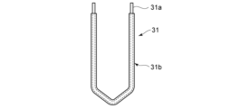
- FIG. 2 is a schematic diagram for illustrating a segment.
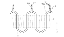
- 1A to 1C are schematic diagrams for illustrating the formation of a coil.
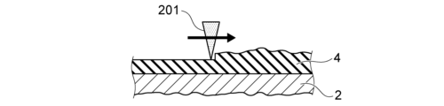
- 11A to 11C are schematic cross-sectional views illustrating removal of a film-like body according to a comparative example.
- 11A to 11C are schematic cross-sectional views illustrating the removal of a film-like body according to another comparative example.
- 1A to 1C are schematic cross-sectional views illustrating removal of a film-like body using a laser removal method according to an embodiment of the present invention.
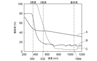
- 1 is a graph illustrating the action and effect of multiphoton absorption.
- 1 is a schematic diagram for illustrating a laser removal device.
- the laser removal method according to this embodiment can be used, for example, to remove unwanted resin-containing films (e.g., adhesives or insulating materials applied in unintended locations) formed on the surface of a metal-containing substrate.
- unwanted resin-containing films e.g., adhesives or insulating materials applied in unintended locations
- rotating electrical machines such as motors and generators are provided with a coil wound around a core.
- multiple segments are inserted into slots provided in the core, and the ends of adjacent segments are then laser welded together to form a coil.
- the coil is then fixed to the core by supplying varnish to the gap between the slot and the coil and allowing the varnish to harden.
- the varnish When the varnish is supplied, it may adhere to the ends, outer parts, and inner parts of the core. If the adhered varnish hardens and forms a film, it may become difficult to insert a rotor into the core or to attach components such as a cover to the ends of the core.
- the laser removal method according to this embodiment can also be used in the manufacture of rotors. In other words, the laser removal method according to this embodiment can be used in the manufacture of rotating electrical machines.
- FIG. 1 is a schematic perspective view illustrating a stator 1. As shown in FIG. 1, a stator 1 is provided with a core 2 and a coil 3 .
- the core 2 can be, for example, a plate-shaped magnetic member stacked in the axial direction of the stator 1 (Z direction in FIG. 1).
- the magnetic member is formed, for example, from an electromagnetic steel plate (silicon steel plate).
- the core 2 has a yoke 21 and a plurality of teeth 22.
- the yoke 21 is cylindrical and located on the outer periphery of the core 2.
- the plurality of teeth 22 are provided at equal intervals on the inner circumferential surface of the yoke 21.
- Each of the plurality of teeth 22 protrudes from the inner circumferential surface of the yoke 21 toward the center of the core 2 and has a shape that extends in the axial direction of the stator 1.
- grooves provided between the teeth 22 become slots 23.
- the shape, number, and size of the teeth 22 are not limited to those shown as examples, and can be changed as appropriate depending on the application, size, and specifications of the rotating electric machine in which the stator 1 is installed.
- the coil 3 includes a plurality of segments 31.
- the segments 31 have a conductor portion 31a and an insulating film 31b (see, for example, FIG. 2).
- the conductor portion 31a is generally U-shaped and is formed from a material with high conductivity.
- the conductor portion 31a is formed from, for example, so-called pure copper or a material containing copper as a main component.
- the conductor portion 31a is formed from, for example, a rectangular wire.
- the insulating film 31b covers the outer surface of the conductor portion 31a. However, the insulating film 31b is not provided near the ends on both sides of the conductor portion 31a, and the conductor portion 31a is exposed.
- the insulating film 31b includes, for example, enamel.
- a single coil 3 is formed by connecting a plurality of segments 31 via welds 31 c. Furthermore, an insulating portion 31d can be provided to cover the exposed portion of the conductor portion 31a and the welded portion 31c.
- the multiple coils 3 can be arranged side by side in the radial direction of the core 2 (a direction passing through the central axis of the core 2 and perpendicular to the Z direction).
- three coils 3 can be provided for U-phase, V-phase, and W-phase.
- the external shape, number, size, etc. of the coils 3 and the segments 31 are not limited to those illustrated, and can be changed as appropriate depending on the application, size, specifications, etc. of the rotating electric machine in which the stator 1 is provided.
- four coils 3 can be arranged side by side in the radial direction of the core 2.
- the core 2 is formed.
- a plurality of plate-shaped magnetic members each having a yoke 21 and portions that will become the teeth 22 are formed.
- the magnetic members are formed by punching an electromagnetic steel plate with a thickness of about 0.05 mm to 1.0 mm.
- the plurality of magnetic members are stacked, and the core 2 is formed by, for example, welding or crimping the plurality of magnetic members.
- the core 2 can also be formed by pressure molding a magnetic material powder and a resin binder.
- FIG. 2 is a schematic diagram illustrating the segment 31.
- a rectangular wire having a predetermined length is bent into an approximately U-shape to form the conductor portion 31a.
- a paint containing enamel or the like is applied to the outer surface of the conductor portion 31a to form the insulating film 31b.
- the surface of the rectangular wire may be coated with a paint containing enamel or the like, cut to a predetermined length, and bent into an approximately U-shape.
- a rectangular wire coated with enamel or the like may be purchased, cut to a predetermined length, and bent into an approximately U-shape.
- the insulating film 31b near both ends of the conductor portion 31a is peeled off to expose the conductor portion 31a. In this manner, a plurality of segments 31 are formed.
- FIG. 3 is a schematic diagram for illustrating the formation of the coil 3.
- each of the multiple segments 31 is mounted in a predetermined slot 23 of the core 2.
- each of the multiple segments 31 is inserted into a predetermined slot 23 from the axial direction of the core 2 (Z direction in Fig. 3).
- one segment 31 is inserted across multiple slots 23.
- a so-called distributed winding coil 3 can be formed.
- a so-called wave winding coil 3 can be formed.
- an insulating paper 32 covering the segments 31 can be provided for each of the slots 23 (see FIG. 6).
- the portion of the segment 31 protruding from the core 2 is bent in a direction approaching the adjacent segment 31.
- the vicinity of the portion of the conductor portion 31a exposed from the insulating film 31b is further bent in the axial direction of the core 2 (Z direction in FIG. 3 ) so that in the circumferential direction of the core 2, the portion of the conductor portion 31a exposed from the insulating film 31b overlaps with the portion of the adjacent conductor portion 31a exposed from the insulating film 31b.
- the above procedure is then repeated to provide a plurality of sets of the segments 31 arranged in the circumferential direction of the core 2 in the radial direction of the core 2 .
- multiple segments 31 are fitted into slots 23 and then bent, this is not limiting.
- multiple segments 31 can be bent, and each of the multiple bent segments 31 can be fitted into a specific slot 23.
- the bent segments 31 can be fitted from the inside to the outside of the core 2.
- a jig can be used to bring the ends of adjacent conductor portions 31a closer together. It is also possible to perform welding without using a jig. However, using a jig can improve the quality of the welded portion 31c and improve the workability of the welding work.
- the ends of adjacent conductor parts 31a can be welded together by irradiating the ends of the conductor parts 31a with laser light. In other words, the ends of adjacent conductor parts 31a can be laser welded together.
- a single coil 3 is formed by connecting multiple segments 31 (conductor portions 31a) in series.
- a single coil 3 is formed by forming multiple coils 3 arranged in the radial direction of core 2. For example, three coils 3 for U-phase, V-phase, and W-phase can be formed by shifting the slots 23 one by one.
- the multiple coils 3 are fixed to the core 2.
- varnish is supplied into the gaps between the slots 23 and the coils 3, and the varnish is hardened to fix the coils 3 to the core 2.
- an insulating material is applied to the exposed portion of the conductor portion 31a and the welded portion 31c of the coil 3 to form an insulating portion 31d.
- the insulating material may be, for example, varnish. If the same material is used to fix the coil 3 and to form the insulating portion 31d, the fixing of the coil 3 and the formation of the insulating portion 31d can be performed in the same process.
- the material used to fix the coil 3 and form the insulating portion 31d is not limited to varnish. For example, a material containing a resin may be used as appropriate.
- the varnish When varnish is supplied to the gap between the slot 23 and the coil 3, the varnish may adhere to the ends, outer portion, and inner portion of the core 2. Also, when varnish is applied to the exposed portion of the conductor portion 31a and the welded portion 31c, for example, the varnish may adhere to the ends, outer portion, and inner portion of the core 2. When the adhered varnish hardens, an unnecessary film-like body 4 is formed on the ends, outer portion, and inner portion of the core 2, as shown in FIG. 1.
- unnecessary film-like bodies 4 are formed on the inner part of the core 2, it becomes difficult to insert a rotor inside the core 2 or to attach a cylindrical insulating cover to the inner part of the core 2.
- unnecessary film-like bodies 4 are formed on the end or outer part of the core 2, it becomes difficult to attach members such as a cover to the end or outer part of the core 2.
- FIG. 4 is a schematic cross-sectional view illustrating the removal of the film body 4 according to the comparative example.
- the film 4 can be removed by irradiating the film 4 with a laser beam 201 to heat the film 4.
- the absorptivity of the laser beam 201 for a material is specific to the material and depends on the wavelength of the laser beam 201. Therefore, the laser beam 201 has a wavelength such that the absorptivity for the resin contained in the film 4 is higher than the absorptivity for the metal contained in the core 2.
- the laser beam 201 has a wavelength of about 355 nm to 532 nm, the film 4 can be removed and damage to the core 2 can be suppressed (see Fig. 7 described later).
- the thickness varies greatly as shown in Fig. 4.
- the thickness varies greatly, if the laser beam 201 is irradiated under predetermined conditions, some of the thicker parts of the film-like body 4 may be left behind. In this case, if the thickness of the film-like body 4 is measured and the irradiation conditions of the laser beam 201 are changed based on the measurement results, the removal operation may take longer or the configuration of the laser removal device may become complicated. Furthermore, since the entire film 4 is removed by heating, the removal process takes longer and consumes more energy.
- the film-like body 4 may be formed near the insulating film 31b or insulating portion 31d of the coil 3.
- the laser light 201 irradiated toward the film-like body 4 may be incident on the insulating film 31b or insulating portion 31d.
- the insulating film 31b and insulating portion 31d contain resin. Therefore, when the laser light 201 is incident on the insulating film 31b or insulating portion 31d, there is a risk of damage being caused to these.
- FIG. 5 is a schematic cross-sectional view illustrating the removal of the film-like body 4 according to another comparative example.
- the interface between the film-like body 4 and the core 2 can be irradiated with laser light 202 to peel off the film-like body 4 from the core 2.
- the laser light 202 has a wavelength such that the absorptivity for the metal contained in the core 2 is higher than the absorptivity for the resin contained in the film-like body 4 (see, for example, FIG. 7 described later).
- the irradiated laser light 202 passes through the film-like body 4 and reaches the interface between the film-like body 4 and the core 2. Then, the film-like body 4 is peeled off from the core 2 by the impact and heat generated by the laser light 202 entering the interface.
- the film-like body 4 can be removed without changing the irradiation conditions of the laser light 202.
- the insulating film 31b and the insulating portion 31d are provided on the surface of the conductor portion 31a, which contains metal. Therefore, when the laser light 201 irradiated toward the film body 4 is incident on the insulating film 31b or the insulating portion 31d, there is a risk that the insulating film 31b or the insulating portion 31d may peel off. Therefore, as in the case described above, a mask is required to cover the insulating film 31b and the insulating portion 31d, and the mask attachment work is required. This results in a decrease in productivity and an increase in manufacturing costs.
- FIG. 6 is a schematic cross-sectional view illustrating the removal of the film-like body 4 using the laser removal method according to an embodiment of the present invention.
- the core 2 is formed in a linear shape. 6, first, the film body 4 is irradiated with the laser light 200. Then, the irradiation position of the laser light 200 is moved. The irradiation position may be moved by scanning the laser light 200, or by moving at least one of the position of the irradiation head and the position of the core 2.
- the laser light 200 has a wavelength that is low in absorption by the resin contained in the film-like body 4.
- the laser light 200 has a wavelength that is difficult to absorb by the film-like body 4 with a single photon.
- the wavelength of the laser light 200 is about 1064 nm.
- the wavelength of the laser light 200 is about 1064 nm, as explained in FIG. 5, the laser light 200 passes through the film body 4 without being absorbed by the film body 4 and reaches the interface between the film body 4 and the core 2. In this case, as explained in FIG. 5, simply irradiating the core 2 with laser light 200 having a wavelength of about 1064 nm may result in the laser light 200 reaching the core 2 being absorbed by the core 2, which may cause damage to the core 2.
- the core 2 has a slot 23 in which a segment 31 is provided. Therefore, laser light 200 may be irradiated inside the slot 23 and reach the segment 31.
- the segment 31 has a conductor portion 31a containing copper and an insulating film 31b containing a resin such as enamel that is provided on the surface of the conductor portion 31a. Therefore, when the laser light 200 reaches the segment 31, the laser light 200 may pass through the insulating film 31b and reach the conductor portion 31a. If the laser light 200 that reaches the conductor portion 31a is absorbed by the conductor portion 31a, damage may occur to the conductor portion 31a.
- insulating paper 32 that covers the segments 31 may be provided for each of the slots 23. Even if insulating paper 32 is provided, the laser light 200 may pass through the insulating paper 32 and the insulating film 31b and reach the conductor portion 31a. In other words, even if insulating paper 32 is provided, there is a risk of damage to the conductor portion 31a.
- the film-like body 4 may be formed at the end or the outer part of the core 2.
- the laser light 200 irradiated to the film-like body 4 may be incident on the segment 31.
- the laser light 200 may pass through the insulating film 31b and reach the conductor part 31a.
- the laser light 200 when the laser light 200 is incident on the part of the segment 31 where the insulating part 31d is provided, the laser light 200 may pass through the insulating part 31d and reach the conductor part 31a. Therefore, even in such a case, the conductor part 31a may be damaged. Furthermore, when the laser light 200 is incident on the segment 31, the insulating film 31b and the insulating portion 31d may peel off.
- multiphoton absorption is caused to occur near the interface between the film 4 and the core 2, or near the interface inside the film 4.
- FIG. 7 is a graph illustrating the action and effect of multiphoton absorption.
- "A” is iron
- "B” is resin
- “C” is a resin different from “B.”
- irradiating with laser light having a wavelength of 532 nm or 355 nm can increase the absorptivity for "B" or "C".
- irradiating with laser light of different wavelengths depending on the type and components of the resin requires irradiating with laser light of different wavelengths depending on the type and components of the resin.
- some of the resin may be left behind in the thicker parts of the film-like body 4, and irradiation conditions may need to be changed depending on the thickness of the film-like body 4.
- multiphoton absorption is caused to occur at the interface between the film 4 and the core 2, or near the interface inside the film 4.
- Single-photon absorption is a state in which a molecule or atom absorbs one photon at a time.
- multiphoton absorption is a state in which a molecule or atom absorbs many photons simultaneously. Therefore, if multiphoton absorption can be caused, high transition energy can be generated with low-energy laser light (for example, laser light with a wavelength of 1064 nm). For example, as shown in FIG.
- the same effect as irradiating with laser light with a wavelength of 532 nm or 355 nm can be obtained in the region where multiphoton absorption has occurred.
- the absorptivity of the laser light 200 to the resin can be increased in the region where multiphoton absorption has occurred.
- the laser light 200 passes through the film-like body 4 where the absorption rate is low, as shown in FIG. 7.
- the absorption rate for the film-like body 4 near the interface can be increased, as shown in FIG. 7.
- the film 4 in the vicinity of the interface can be removed.
- the film 4 can be peeled off from the core 2.
- the film 4 can be removed using an air blower or by an operator. As shown in FIG. 6, a portion of the film 4 may remain inside the slot 23, but since the film 4 is insulating, it does not need to be removed. Since the bonding area of the film 4 remaining inside the slot 23 is small, it can be removed relatively easily.
- multiphoton absorption can be caused by concentrating the laser light 200 to increase the light intensity. Therefore, by focusing the laser light 200 at the interface between the film 4 and the core 2, or at a position near the interface inside the film 4, multiphoton absorption can be caused at these positions.
- multiphoton absorption occurs at the focal position of the laser light 200, single photon absorption with lower energy than multiphoton absorption will occur at a position different from the focal position. Therefore, even if the laser light 200 is irradiated at an unintended position, it is possible to suppress the occurrence of multiphoton absorption at the unintended position. For example, as described above, even if the laser light 200 is irradiated to the inside of the slot 23 or the segment 31 exposed from the core 2, it is possible to suppress the occurrence of multiphoton absorption at the irradiated position. Therefore, it is possible to suppress the occurrence of damage to the conductor portion 31a and the peeling of the insulating film 31b and the insulating portion 31d. Also, since a mask covering the insulating film 31b and the insulating portion 31d can be omitted, it is possible to improve productivity and reduce manufacturing costs.
- the probability of multiphoton absorption occurring is proportional to the square of the light intensity.
- the light intensity can be increased by shortening the pulse width of the laser light 200. Therefore, by controlling the pulse width of the laser light 200, the probability of multiphoton absorption occurring can be increased. If the probability of multiphoton absorption occurring increases, it becomes easier to remove the film-like body 4.
- the spot diameter of the laser light 200 at the focal position can be approximately 10 ⁇ m
- the pulse width can be approximately 10 psec
- the average output can be approximately 50 W.
- multiphoton absorption occurs at the interface between the film 4 and the core 2, so that the film 4 can be removed reliably even if the thickness of the film 4 varies or the core 2 has steps or gaps. Furthermore, by causing multiphoton absorption at the interface between the film 4 and the core 2, damage to the core 2 can be suppressed. Furthermore, even if the laser light 200 is incident on the insulating film 31b or insulating portion 31d near the film 4, multiphoton absorption does not occur, so the insulating film 31b or insulating portion 31d will not peel off.
- the wavelength of the laser light 200, the spot diameter at the focal position, the output of the laser light 200, the position where multiphoton absorption occurs, and the like may be appropriately changed as necessary.
- the wavelength of the laser light 200, the spot diameter at the focal position, the output of the laser light 200, the position at which multiphoton absorption occurs, and the like can be appropriately determined by, for example, performing experiments or simulations.
- the laser removal method is a laser removal method in which a film-like body 4 containing resin and formed on a substrate is irradiated with laser light 200 to remove the film-like body 4.
- the film-like body 4 is irradiated with laser light 200 having a wavelength that is difficult to absorb in the film-like body 4 with a single photon, causing multiphoton absorption at a predetermined position inside the film-like body 4.
- this laser removal method focuses the laser light 200 at a predetermined position inside the film body 4.
- this laser removal method shortens the pulse width of the laser light 200, thereby increasing the light intensity at the focal position of the laser light 200 and increasing the probability of multiphoton absorption occurring.
- the method for manufacturing the rotating electric machine can include the following steps.
- laser light 200 having a wavelength that is unlikely to be absorbed in film-like body 4 with a single photon is irradiated onto film-like body 4, causing multi-photon absorption at a predetermined position inside film-like body 4.
- the specified position inside the membrane body 4 can be the position of the interface between the membrane body 4 and the core 2, or a position near the interface inside the membrane body 4.
- the laser light 200 can also include light with a wavelength of at least 1064 nm.
- the laser removal device 100 irradiates a film-like body 4 formed on a base material (for example, a core 2) with laser light to remove the film-like body 4.
- a base material for example, a core 2
- laser light to remove the film-like body 4.
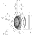
- FIG. 8 is a schematic diagram illustrating the laser removal device 100.
- the laser removal device 100 includes, for example, a laser irradiation unit 101, a detection unit 102, a placement unit 103, an illumination unit 104, and a controller 105.
- a plurality of laser irradiation units 101 can be provided depending on the position where the film-like body 4 is formed. For example, as shown in FIG. 8, a laser irradiation unit 101 for removing the film-like body 4 formed at the end of the core 2, a laser irradiation unit 101 for removing the film-like body 4 formed on the outer part of the core 2, and a laser irradiation unit 101 for removing the film-like body 4 formed on the inner part of the core 2 can be provided.
- the laser irradiation unit 101 irradiates the film-like body 4 with laser light 200 having a wavelength that is difficult to absorb in the film-like body 4 with a single photon, causing multi-photon absorption at a predetermined position inside the film-like body 4.
- the laser irradiation unit 101 also moves the irradiation position of the laser light 200.
- the laser irradiation unit 101 has, for example, a laser oscillator 101a and a laser head 101b. Note that when multiple laser irradiation units 101 are provided, the laser oscillator 101a can be used for both.
- the laser oscillator 101a oscillates laser light 200 having a wavelength that is difficult to absorb by a single photon in the film body 4.
- the laser oscillator 101a can be, for example, an ytterbium nanosecond pulse laser oscillator.
- the wavelength of the laser light 200 is about 1064 nm.
- the laser oscillator 101a may also include a scanning device such as a galvanometer mirror, and a pulse width control device.
- the laser oscillator 101a moves the irradiation position on the film body 4 using a scanning device such as a galvanometer mirror.
- the laser oscillator 101a increases the light intensity by shortening the pulse width using a pulse width control device. Note that the pulse width only needs to be short, so it may be a predetermined value.
- the laser head 101b irradiates the film-like body 4 with the laser light 200 transmitted from the laser oscillator 101a.
- the laser head 101b may be equipped with a reflecting mirror, a focusing lens, etc. Therefore, the laser head 101b can focus the laser light 200 at the position of the interface between the film-like body 4 and the core 2, or at a position near the interface inside the film-like body 4.
- a laser rangefinder or the like that measures the distance between the laser head 101b and the surface of the core 2 may be provided.
- the laser head 101b can control the focus of the laser light 200 to the aforementioned position based on the distance measured by the laser rangefinder or the like.
- the distance between the laser head 101b and the surface of the core 2 may be adjusted to a predetermined value. In such a case, the laser rangefinder or the like may be omitted.
- the detection unit 102 detects the position of the film-like body 4 formed on the core 2.
- a plurality of detection units 102 may be provided according to the positions at which the film-like body 4 is formed. For example, as shown in Fig. 8, a detection unit 102 for detecting the film-like body 4 formed on the end of the core 2, a detection unit 102 for detecting the film-like body 4 formed on the outer part of the core 2, and a detection unit 102 for detecting the film-like body 4 formed on the inner part of the core 2 may be provided.
- the detection unit 102 may be, for example, a CCD image sensor.
- the mounting unit 103 holds the stator 1 and changes the position of the stator 1. For example, the mounting unit 103 rotates the stator 1 around the central axis of the core 2.
- the mounting unit 103 can also arbitrarily set the rotational position of the stator 1.
- the mounting unit 103 can be equipped with a control motor such as a servo motor, for example.
- the illumination unit 104 irradiates light toward the stator 1.
- the illumination unit 104 irradiates light in the ultraviolet range toward the stator 1.
- the film-like body 4 is excited and emits light.
- the detection unit 102 detects the film-like body 4.
- the illumination unit 104 can be equipped with a light-emitting diode that irradiates ultraviolet light with a peak wavelength of about 405 nm, for example.
- the controller 105 controls the operation of each element provided in the laser removal device 100 to execute the laser removal method described above.
- the controller 105 has an arithmetic unit such as a CPU (Central Processing Unit) and a storage unit such as a semiconductor memory.
- the controller 105 is, for example, a computer.
- the storage unit can store a control program that controls the operation of each element provided in the laser removal device 100.
- the arithmetic unit controls the operation of each element provided in the laser removal device 100 using the control program stored in the storage unit and data input by the operator, etc.
- the controller 105 controls the illumination unit 104 to irradiate light onto the stator 1.
- the controller 105 also controls the mounting unit 103 to move the position of the stator 1.
- the controller 105 calculates the position, planar shape, size, etc. of the film-like body 4 based on the position information from the mounting unit 103 and information from the detection unit 102 (e.g., the shape and size of the film-like body 4, etc.).
- the controller 105 can calculate the planar shape, size, etc. of the film-like body 4 by performing image processing.
- the controller 105 controls the placement unit 103 to move the film-like body 4 to be removed to the irradiation area of the laser irradiation unit 101 .
- the controller 105 controls the laser irradiation unit 101 to execute the above-mentioned laser removal method, thereby removing the film-like body 4.
- the procedure for removing the film-like body 4 is similar to that of the above-mentioned laser removal method, and therefore a detailed description thereof will be omitted.
Landscapes
- Engineering & Computer Science (AREA)
- Physics & Mathematics (AREA)
- Thermal Sciences (AREA)
- Optics & Photonics (AREA)
- Plasma & Fusion (AREA)
- Mechanical Engineering (AREA)
- Manufacturing & Machinery (AREA)
- Power Engineering (AREA)
- Laser Beam Processing (AREA)
Abstract
実施形態に係るレーザ除去方法は、樹脂を含み、基材の上に形成された膜状体にレーザ光を照射して、前記膜状体を除去するレーザ除去方法である。前記レーザ除去方法は、一光子では前記膜状体において吸収が生じ難い波長を有するレーザ光を前記膜状体に照射し、前記膜状体の内部の所定の位置において、多光子吸収を生じさせる。
Description
本発明の実施形態は、レーザ除去方法、回転電機の製造方法、およびレーザ除去装置に関する。
基材の上に、樹脂を含む不要な膜状体が形成される場合がある。例えば、鉄などの金属を含む基材の表面に、樹脂を塗布する際に、意図しない領域に樹脂が付着する場合がある。例えば、絶縁処理を施す際に、ワニスなどの樹脂が基材に供給される場合がある。この際、ワニスなどの樹脂が基材の意図しない領域に付着する場合がある。基材の意図しない領域に付着した樹脂が硬化して膜状体が形成されると、基材に部材を取り付けるのが困難となったり、商品価値が低下したりするおそれがある。
そのため、基材の材料である金属よりも、膜状体の材料である樹脂に吸収されやすい波長を有するレーザ光を、膜状体に照射して膜状体を除去する技術が提案されている。この様にすれば、基材に損傷が発生するのを抑制しつつ、膜状体の除去を行うことができる。しかしながら、膜状体は、厚みが管理されたものではないため、厚みのばらつきが大きくなる。厚みのばらつきが大きくなると、厚みの厚い部分に取り残しが発生する場合がある。
またさらに、膜状体が、樹脂を含む部材の近傍に形成される場合がある。膜状体を除去するためのレーザ光が、膜状体の近傍にある樹脂を含む部材に入射すると、部材が損傷するおそれがある。この場合、レーザ光を照射する前に、膜状体の近傍にある部材をマスクで覆うようにすれば、部材が損傷するのを抑制することができる。しかしながら、この様にすると、部材を覆うマスクと、マスクの装着作業が必要となる。そのため、生産性の低下や製造コストの増大を招くことになる。
また、膜状体の材料である樹脂よりも、基材の材料である金属に吸収されやすい波長を有するレーザ光を、膜状体に照射して膜状体を除去する技術が提案されている。この様なレーザ光は、膜状体を透過して、膜状体と基材の界面に到達する。そして、レーザ光が界面に入射することで発生した衝撃や熱などで、膜状体が基材から剥離される。そのため、この様なレーザ光を用いれば、膜状体の厚みがばらついたとしても膜状体の除去を行うことができる。しかしながら、この様なレーザ光を用いると、基材に損傷が発生したり、基材の段差や隙間の部分において膜状体の除去ができなくなったりするおそれがある。
またさらに、膜状体が、樹脂で被覆された金属を含む部材の近傍に形成される場合がある。膜状体を除去するためのレーザ光が、膜状体の近傍にある樹脂で被覆された部材に入射すると、樹脂が剥離するおそれがある。そのため、この様な場合にも、部材を覆うマスクと、マスクの装着作業が必要となる。その結果、生産性の低下や製造コストの増大を招くことになる。
そこで、簡易な方法で、膜状体以外の部材に損傷が発生するのを抑制しつつ、膜状体の除去を行うことができる技術の開発が望まれていた。
そこで、簡易な方法で、膜状体以外の部材に損傷が発生するのを抑制しつつ、膜状体の除去を行うことができる技術の開発が望まれていた。
本発明が解決しようとする課題は、簡易な方法で、膜状体以外の部材に損傷が発生するのを抑制しつつ、膜状体の除去を行うことができるレーザ除去方法、回転電機の製造方法、およびレーザ除去装置を提供することである。
実施形態に係るレーザ除去方法は、樹脂を含み、基材の上に形成された膜状体にレーザ光を照射して、前記膜状体を除去するレーザ除去方法である。前記レーザ除去方法は、一光子では前記膜状体において吸収が生じ難い波長を有するレーザ光を前記膜状体に照射し、前記膜状体の内部の所定の位置において、多光子吸収を生じさせる。
本実施の形態に係るレーザ除去方法は、例えば、金属を含む基材の表面に形成された樹脂を含む不要な膜状体(例えば、意図しない位置に塗布された接着剤や、絶縁材料など)を除去する際に用いることができる。
例えば、モータや発電機などの回転電機には、コアに巻き付けられたコイルが設けられている。近年においては、複数のセグメントを、コアに設けられたスロットに挿入した後に、隣接するセグメントの端部同士をレーザ溶接してコイルを形成している。そして、スロットとコイルとの間の隙間に、ワニスを供給し、ワニスを硬化させることで、コイルをコアに固定している。
ここで、ワニスを供給した際に、コアの端部、外側部、内側部などにワニスが付着する場合がある。付着したワニスが硬化して膜状体が形成されると、コアの内部にロータを挿入するのが困難となったり、コアの端部などにカバーなどの部材を取り付けるのが困難となったりする場合がある。
そのため、以下においては、一例として、ステータの製造において、コアの内側部などに形成された不要なワニスの膜を除去する場合について説明する。なお、本実施の形態に係るレーザ除去方法は、ロータの製造においても用いることができる。すなわち、本実施の形態に係るレーザ除去方法は、回転電機の製造において用いることができる。
以下、図面を参照しつつ、実施の形態について例示をする。なお、各図面中、同様の構成要素には同一の符号を付して詳細な説明は適宜省略する。
まず、ステータ1について例示をする。
図1は、ステータ1を例示するための模式斜視図である。
図1に示すように、ステータ1には、コア2、およびコイル3が設けられている。
まず、ステータ1について例示をする。
図1は、ステータ1を例示するための模式斜視図である。
図1に示すように、ステータ1には、コア2、およびコイル3が設けられている。
コア2は、例えば、板状の磁性体部材が、ステータ1の軸方向(図1中のZ方向)に複数積層されたものとすることができる。磁性体部材は、例えば、電磁鋼板(珪素鋼板)から形成される。コア2は、ヨーク21と、複数のティース22を有する。ヨーク21は、筒状を呈し、コア2の外周側に位置している。複数のティース22は、ヨーク21の内周面に等間隔に設けられている。複数のティース22のそれぞれは、ヨーク21の内周面からコア2の中心に向けて突出するとともに、ステータ1の軸方向に延びる形態を有している。また、ティース22とティース22との間に設けられる溝がスロット23となる。なお、ティース22の形状、数、大きさは、例示をしたものに限定されるわけではなく、ステータ1が設けられる回転電機の用途、大きさ、仕様などに応じて適宜変更することができる。
コイル3は、複数のセグメント31を含んでいる。セグメント31は、導体部31a、および絶縁膜31bを有する(例えば、図2を参照)。導体部31aは、略U字状を呈し、導電率の高い材料から形成される。導体部31aは、例えば、いわゆる純銅や、銅を主成分とする材料から形成される。導体部31aは、例えば、平角線から形成される。絶縁膜31bは、導体部31aの外面を覆っている。ただし、導体部31aの両側の端部の近傍には、絶縁膜31bが設けられておらず、導体部31aが露出している。絶縁膜31bは、例えば、エナメルなどを含む。
隣接する導体部31aの端部同士は、レーザ溶接されている。複数のセグメント31が溶接部31cを介して接続されることで、1つのコイル3が形成されている。
また、導体部31aが露出する部分、および溶接部31cを覆う絶縁部31dを設けることができる。
また、導体部31aが露出する部分、および溶接部31cを覆う絶縁部31dを設けることができる。
コイル3は、複数設けられる。複数のコイル3は、コア2の径方向(コア2の中心軸を通りZ方向に直交する方向)に並べて設けることができる。例えば、図1に例示をしたように、U相、V相、およびW相の3つのコイル3を設けることができる。なお、コイル3とセグメント31の外観形状、数、大きさなどは、例示をしたものに限定されるわけではなく、ステータ1が設けられる回転電機の用途、大きさ、仕様などに応じて適宜変更することができる。例えば、コア2の径方向に4つのコイル3が並べて設けられていてもよい。
次に、ステータ1の製造方法とともに、本実施の形態に係るレーザ除去方法について説明する。
まず、コア2を形成する。例えば、ヨーク21と、複数のティース22となる部分とを有する板状の磁性体部材を複数形成する。例えば、磁性体部材は、厚みが0.05mm~1.0mm程度の電磁鋼板を打抜き加工により加工することで形成する。そして、複数の磁性体部材を積層し、例えば、複数の磁性体部材を溶接したり、カシメたりしてコア2を形成する。なお、コア2は、磁性材粉末と、樹脂バインダを加圧成形することで形成することもできる。
まず、コア2を形成する。例えば、ヨーク21と、複数のティース22となる部分とを有する板状の磁性体部材を複数形成する。例えば、磁性体部材は、厚みが0.05mm~1.0mm程度の電磁鋼板を打抜き加工により加工することで形成する。そして、複数の磁性体部材を積層し、例えば、複数の磁性体部材を溶接したり、カシメたりしてコア2を形成する。なお、コア2は、磁性材粉末と、樹脂バインダを加圧成形することで形成することもできる。
また、コイル3の構成要素となるセグメント31を複数形成する。
図2は、セグメント31を例示するための模式図である。
まず、所定の長さを有する平角線を略U字状に折り曲げることで導体部31aを形成する。続いて、導体部31aの外面にエナメルなどを含む塗料を塗布して絶縁膜31bを形成する。なお、平角線の表面にエナメルなどを含む塗料を塗布し、これを所定の長さに切断して略U字状に折り曲げるようにしてもよい。また、エナメル塗装などが施された平角線を購入などして、これを所定の長さに切断して略U字状に折り曲げるようにしてもよい。
図2は、セグメント31を例示するための模式図である。
まず、所定の長さを有する平角線を略U字状に折り曲げることで導体部31aを形成する。続いて、導体部31aの外面にエナメルなどを含む塗料を塗布して絶縁膜31bを形成する。なお、平角線の表面にエナメルなどを含む塗料を塗布し、これを所定の長さに切断して略U字状に折り曲げるようにしてもよい。また、エナメル塗装などが施された平角線を購入などして、これを所定の長さに切断して略U字状に折り曲げるようにしてもよい。
次に、図2に示すように、導体部31aの両側の端部の近傍にある絶縁膜31bを剥がして、導体部31aを露出させる。
以上の様にして、セグメント31を複数形成する。
以上の様にして、セグメント31を複数形成する。
次に、複数のセグメント31の端部同士を溶接してコイル3を形成する。
図3は、コイル3の形成を例示するための模式図である。
まず、図3に示すように、複数のセグメント31のそれぞれをコア2の所定のスロット23に装着する。例えば、複数のセグメント31のそれぞれをコア2の軸方向(図3中のZ方向)から所定のスロット23に挿入する。この際、1つのセグメント31は、複数のスロット23を跨いで挿入される。例えば、いわゆる分布巻きのコイル3が形成されるようにすることができる。また、いわゆる波巻きのコイル3が形成されるようにすることもできる。
また、複数のスロット23毎に、セグメント31を覆う絶縁紙32を設けることもできる(図6を参照)。
図3は、コイル3の形成を例示するための模式図である。
まず、図3に示すように、複数のセグメント31のそれぞれをコア2の所定のスロット23に装着する。例えば、複数のセグメント31のそれぞれをコア2の軸方向(図3中のZ方向)から所定のスロット23に挿入する。この際、1つのセグメント31は、複数のスロット23を跨いで挿入される。例えば、いわゆる分布巻きのコイル3が形成されるようにすることができる。また、いわゆる波巻きのコイル3が形成されるようにすることもできる。
また、複数のスロット23毎に、セグメント31を覆う絶縁紙32を設けることもできる(図6を参照)。
続いて、セグメント31の、コア2から突出している部分を、隣接するセグメント31に近づく方向に折り曲げる。そして、さらに、導体部31aの、絶縁膜31bから露出している部分の近傍を、コア2の軸方向(図3中のZ方向)に折り曲げる。コア2の周方向において、導体部31aの、絶縁膜31bから露出している部分は、隣接する導体部31aの、絶縁膜31bから露出している部分と重なるようにする。
そして、以上の手順を繰り返し行うことで、コア2の周方向に並ぶ複数のセグメント31を、コア2の径方向に複数組設ける。
そして、以上の手順を繰り返し行うことで、コア2の周方向に並ぶ複数のセグメント31を、コア2の径方向に複数組設ける。
なお、複数のセグメント31をスロット23に装着した後に折り曲げ加工を行う場合を例示したがこれに限定されるわけではない。例えば、複数のセグメント31に折り曲げ加工を施し、折り曲げ加工が施された複数のセグメント31のそれぞれを所定のスロット23に装着することもできる。この場合、折り曲げ加工が施されたセグメント31を、コア2の内側から外側に向けて装着することができる。
続いて、隣接するセグメント31(導体部31a)の端部同士を溶接して、スロット23に装着されたコイル3を形成する。溶接を行う際には、隣接する導体部31aの端部同士を近づける治具を用いることができる。なお、治具を用いずに溶接を行うこともできる。ただし、治具を用いれば、溶接部31cの品質を向上させたり、溶接作業の作業性を向上させたりすることができる。
隣接する導体部31aの端部同士の溶接は、導体部31aの端部にレーザ光を照射して行うことができる。すなわち、隣接する導体部31aの端部同士をレーザ溶接することができる。
隣接する導体部31aの端部同士を溶接することで、図1および図3に例示をした溶接部31cが形成される。また、複数のセグメント31(導体部31a)が直列接続されることで、1つのコイル3が形成される。また、コア2の径方向に並ぶ複数のコイル3が形成される。例えば、スロット23を1つずつずらせて、U相、V相、およびW相の3つのコイル3を形成することができる。
次に、複数のコイル3をコア2に固定する。例えば、スロット23とコイル3との間の隙間にワニスを供給し、ワニスを硬化させることでコイル3をコア2に固定する。
また、図3に示すように、コイル3の、導体部31aが露出する部分、および溶接部31cに絶縁材料を塗布して絶縁部31dを形成する。絶縁材料は、例えば、ワニスとすることができる。コイル3の固定と、絶縁部31dの形成に用いる材料が同じであれば、コイル3の固定と、絶縁部31dの形成を同じ工程で行うことができる。
なお、コイル3の固定と、絶縁部31dの形成に用いる材料はワニスに限定されるわけではない。例えば、樹脂を含む材料を適宜用いることができる。
なお、コイル3の固定と、絶縁部31dの形成に用いる材料はワニスに限定されるわけではない。例えば、樹脂を含む材料を適宜用いることができる。
ここで、スロット23とコイル3との間の隙間に、ワニスを供給した際に、ワニスがコア2の端部、外側部、および内側部などに付着する場合がある。また、導体部31aが露出する部分、および溶接部31cに、例えば、ワニスを塗布した際に、ワニスがコア2の端部、外側部、および内側部などに付着する場合がある。付着したワニスが硬化すると、図1に示すように、コア2の端部、外側部、および内側部などに、不要な膜状体4が形成される。
例えば、不要な膜状体4がコア2の内側部に形成されていると、コア2の内側にロータを挿入したり、コア2の内側部に筒状の絶縁カバーを取り付けたりするのが困難となる。例えば、不要な膜状体4がコア2の端部や外側部に形成されていると、コア2の端部や外側部にカバーなどの部材を取り付けるのが困難となる。
そこで、次に、膜状体4の除去を行う。膜状体4の除去は、膜状体4に向けてレーザ光を照射することで行う。
図4は、比較例に係る膜状体4の除去を例示するための模式断面図である。
図4に示すように、膜状体4にレーザ光201を照射して膜状体4を加熱することで、膜状体4を除去することができる。この場合、レーザ光201の、材料に対する吸収率は、材料固有のものであり、レーザ光201の波長に依存する。そのため、レーザ光201は、膜状体4に含まれる樹脂に対する吸収率が、コア2に含まれる金属に対する吸収率よりも高くなるような波長を有するものとする。例えば、355nm~532nm程度の波長を有するレーザ光201とすれば、膜状体4の除去を行うことができ、且つ、コア2に損傷が発生するのを抑制することができる(後述する図7を参照)。
図4は、比較例に係る膜状体4の除去を例示するための模式断面図である。
図4に示すように、膜状体4にレーザ光201を照射して膜状体4を加熱することで、膜状体4を除去することができる。この場合、レーザ光201の、材料に対する吸収率は、材料固有のものであり、レーザ光201の波長に依存する。そのため、レーザ光201は、膜状体4に含まれる樹脂に対する吸収率が、コア2に含まれる金属に対する吸収率よりも高くなるような波長を有するものとする。例えば、355nm~532nm程度の波長を有するレーザ光201とすれば、膜状体4の除去を行うことができ、且つ、コア2に損傷が発生するのを抑制することができる(後述する図7を参照)。
ところが、膜状体4は、厚みを管理するなどして意図して形成されたものではないため、図4に示すように、厚みのばらつきが大きくなる。厚みのばらつきが大きい場合に、予め定められた条件でレーザ光201を照射すると、膜状体4の厚みの厚い部分に取り残しが生ずる場合がある。この場合、膜状体4の厚みを測定し、測定結果に基づいてレーザ光201の照射条件を変えると、除去作業の時間が長くなったり、レーザ除去装置の構成が複雑となったりする。
また、膜状体4の全体を加熱により除去するので、除去作業の時間が長くなったり、消費エネルギーが多くなったりすることになる。
また、膜状体4の全体を加熱により除去するので、除去作業の時間が長くなったり、消費エネルギーが多くなったりすることになる。
また、膜状体4が、コイル3の絶縁膜31bや絶縁部31dの近傍に形成される場合がある。この様な場合には、膜状体4に向けて照射されたレーザ光201が、絶縁膜31bや絶縁部31dに入射する場合がある。前述した様に、絶縁膜31bや絶縁部31dは、樹脂を含んでいる。そのため、レーザ光201が、絶縁膜31bや絶縁部31dに入射すると、これらに損傷が発生するおそれがある。
この場合、レーザ光201を照射する前に、絶縁膜31bや絶縁部31dをマスクで覆うようにすれば、絶縁膜31bや絶縁部31dが損傷するのを抑制することができる。しかしながら、この様にすると、絶縁膜31bや絶縁部31dを覆うマスクと、マスクの装着作業が必要となる。そのため、生産性の低下や製造コストの増大を招くことになる。
図5は、他の比較例に係る膜状体4の除去を例示するための模式断面図である。 図5に示すように、膜状体4とコア2との界面にレーザ光202を照射して、膜状体4をコア2から剥離させることができる。この場合、レーザ光202は、コア2に含まれる金属に対する吸収率が、膜状体4に含まれる樹脂に対する吸収率よりも高くなるような波長を有するものとする(例えば、後述する図7を参照)。例えば、1064nm程度の波長を有するレーザ光202とすれば、照射されたレーザ光202は、膜状体4を透過して、膜状体4とコア2の界面に到達する。そして、レーザ光202が界面に入射することで発生した衝撃や熱などで、膜状体4がコア2から剥離される。
この様にすれば、膜状体4の厚みにばらつきがあっても、レーザ光202の照射条件を変えずに膜状体4の除去を行うことができる。
しかしながら、この様にすると、コア2に損傷が発生するおそれがある。また、絶縁膜31bや絶縁部31dは、金属を含む導体部31aの表面に設けられている。そのため、膜状体4に向けて照射されたレーザ光201が、絶縁膜31bや絶縁部31dに入射すると、絶縁膜31bや絶縁部31dが剥離するおそれがある。そのため、前述した場合と同様に、絶縁膜31bや絶縁部31dを覆うマスクと、マスクの装着作業が必要となる。その結果、生産性の低下や製造コストの増大を招くことになる。
図6は、本発明の実施形態に係るレーザ除去方法を用いた膜状体4の除去を例示するための模式断面図である。
なお、煩雑となるのを避けるために、コア2の形状を直線状としている。
図6に示すように、まず、レーザ光200を膜状体4に照射する。そして、レーザ光200の照射位置を移動させる。照射位置の移動は、レーザ光200を走査することで行ってもよいし、照射ヘッドの位置、およびコア2の位置の少なくともいずれかを移動させるようにしてもよい。
なお、煩雑となるのを避けるために、コア2の形状を直線状としている。
図6に示すように、まず、レーザ光200を膜状体4に照射する。そして、レーザ光200の照射位置を移動させる。照射位置の移動は、レーザ光200を走査することで行ってもよいし、照射ヘッドの位置、およびコア2の位置の少なくともいずれかを移動させるようにしてもよい。
レーザ光200は、膜状体4に含まれる樹脂に対する吸収率が低くなるような波長を有するものとする。例えば、レーザ光200は、膜状体4において、一光子では吸収が生じ難い波長を有する。例えば、レーザ光200の波長は、1064nm程度である。
レーザ光200の波長が1064nm程度であれば、図5において説明した様に、レーザ光200は、膜状体4に吸収されずに膜状体4を透過して、膜状体4とコア2の界面に到達する。この場合、図5において説明した様に、単に、波長が1064nm程度のレーザ光200を照射すると、コア2に到達したレーザ光200がコア2に吸収されて、コア2に損傷が発生するおそれがある。
また、図6に示すように、コア2は、セグメント31が設けられるスロット23を有する。そのため、レーザ光200がスロット23の内部に照射されて、セグメント31に到達する場合がある。セグメント31は、銅を含む導体部31aと、導体部31aの表面に設けられエナメルなどの樹脂を含む絶縁膜31bとを有する。そのため、レーザ光200がセグメント31に到達すると、レーザ光200が絶縁膜31bを透過して、導体部31aに到達する場合がある。導体部31aに到達したレーザ光200が導体部31aに吸収されると、導体部31aに損傷が発生するおそれがある。
なお、図6に示す様に、複数のスロット23毎に、セグメント31を覆う絶縁紙32が設けられる場合がある。絶縁紙32が設けられていても、レーザ光200は、絶縁紙32、および絶縁膜31bを透過して、導体部31aに到達する場合がある。すなわち、絶縁紙32が設けられていても、導体部31aに損傷が発生するおそれがある。
また、図1に示すように、膜状体4が、コア2の端部や外側部に形成される場合がある。この場合、コア2の端部に形成された膜状体4の位置がセグメント31の近傍であったり、コア2の外側部に形成された膜状体4の位置がコア2の端部の近傍であったりすると、膜状体4に照射されたレーザ光200がセグメント31に入射する場合がある。この場合、レーザ光200がセグメント31の絶縁膜31bが設けられた部分に入射すると、レーザ光200が絶縁膜31bを透過して、導体部31aに到達する場合がある。また、レーザ光200がセグメント31の絶縁部31dが設けられた部分に入射すると、レーザ光200が絶縁部31dを透過して、導体部31aに到達する場合がある。そのため、この様な場合にも導体部31aに損傷が発生するおそれがある。
また、レーザ光200がセグメント31に入射すると、絶縁膜31bや絶縁部31dが剥離する場合もある。
また、レーザ光200がセグメント31に入射すると、絶縁膜31bや絶縁部31dが剥離する場合もある。
この場合、前述した様に、絶縁膜31bや絶縁部31dを覆うマスクを設けると、生産性の低下や製造コストの増大を招くことになる。
そこで、本実施の形態に係るレーザ除去方法においては、膜状体4とコア2の界面の位置、あるいは、膜状体4の内部の界面の位置の近傍において、多光子吸収が生じる様にしている。
図7は、多光子吸収の作用、効果を例示するためのグラフである。
図中の「A」は鉄であり、「B」は樹脂であり、「C」は「B」とは異なる樹脂である。
図中の「A」は鉄であり、「B」は樹脂であり、「C」は「B」とは異なる樹脂である。
図7から分かるように、単に、波長が1064nmのレーザ光200を照射すると、レーザ光200は吸収率の低い「B」または「C」を透過する。また、レーザ光200は吸収率の高い「A」に吸収される。そのため、「A」の表面に「B」または「C」が設けられていると、前述した様な「A」の損傷や、意図しない「B」または「C」の剥離が生じるおそれがある。
この場合、図7から分かるように、波長が532nmや355nmのレーザ光を照射すると、「B」または「C」に対する吸収率を高くすることができる。しかしながら、この様にすると、樹脂の種類や成分に応じて、波長の異なるレーザ光を照射する必要がある。また、図4において説明した様に、膜状体4の厚みの厚い部分に取り残しが生じたり、膜状体4の厚みに応じて照射条件を変えたりする必要がある。
そこで、本実施の形態に係るレーザ除去方法においては、膜状体4とコア2の界面の位置、あるいは、膜状体4の内部の界面の位置の近傍において、多光子吸収が生じるようにしている。一光子吸収は、分子や原子が光子を一個ずつ吸収する状態である。一方、多光子吸収は、分子や原子が多数個の光子を同時に吸収する状態である。そのため、多光子吸収を生じさせることができれば、エネルギーの低いレーザ光(例えば、波長が1064nmのレーザ光)で高い遷移エネルギーを生じさせることができる。例えば、図7に示すように、波長が1064nmのレーザ光200を照射する場合であっても、多光子吸収を生じさせた領域においては、波長が532nmや355nmのレーザ光を照射したのと同様の効果を得ることができる。すなわち、多光子吸収を生じさせた領域においては、樹脂に対するレーザ光200の吸収率を高くすることができる。
例えば、波長が1064nmのレーザ光200を膜状体4に照射した場合、図7に示すように、吸収率が低い膜状体4においては、レーザ光200が膜状体4を透過する。一方、膜状体4とコア2の界面の位置、あるいは、膜状体4の内部の界面の位置の近傍において、多光子吸収を生じさせれば、図7に示すように、界面の近傍にある膜状体4に対する吸収率を高くすることができる。
そのため、図6に示すように、界面の近傍にある膜状体4のみを除去することができる。界面の近傍にある膜状体4が除去されれば、コア2から膜状体4を剥離することができる。なお、界面の近傍にある膜状体4が除去された後に、エアブローなどを用いて膜状体4を取り除いたり、作業者が膜状体4を取り除いたりすることができる。また、図6に示すように、スロット23の内部に膜状体4の一部が残留する場合があるが、膜状体4は絶縁性を有しているため取り除く必要はない。なお、スロット23の内部に残留する膜状体4は、接合面積が小さいので、比較的容易に取り除くこともできる。
ここで、多光子吸収は、レーザ光200を集光して光強度を高めることで生じさせることができる。そのため、レーザ光200の焦点を、膜状体4とコア2の界面の位置、あるいは、膜状体4の内部の界面の近傍の位置に合わせれば、これらの位置において多光子吸収を生じさせることができる。
また、レーザ光200の焦点の位置において、多光子吸収を生じさせる様にすれば、焦点の位置とは異なる位置においては、多光子吸収よりもエネルギーの低い一光子吸収が生じることになる。そのため、レーザ光200が意図しない位置に照射されたとしても、意図しない位置においては多光子吸収が生じるのを抑制することができる。例えば、前述した様に、レーザ光200がスロット23の内部や、コア2から露出するセグメント31に照射されたとしても、照射された位置において多光子吸収が生じるのを抑制することができる。そのため、導体部31aに損傷が発生したり、絶縁膜31bや絶縁部31dが剥離したりするのを抑制することができる。また、絶縁膜31bや絶縁部31dを覆うマスクを省くことができるので、生産性の向上や製造コストの低減を図ることができる。
また、多光子吸収が生じる確率は、光強度の自乗に比例する。例えば、レーザ光200のパルス幅を短くすれば光強度を高くすることができる。そのため、レーザ光200のパルス幅を制御すれば、多光子吸収が生じる確率を高めることができる。多光子吸収が生じる確率が高くなれば、膜状体4の除去が容易となる。
例えば、波長が1064nmのレーザ光200を照射する場合、焦点位置におけるレーザ光200のスポット径は10μm程度、パルス幅10psec程度、平均出力50W程度とすることができる。
本実施の形態に係るレーザ除去方法においては、膜状体4とコア2の界面の位置において、多光子吸収を生じさせるので、膜状体4の厚みがばらついたり、コア2に段差や隙間があったりしても膜状体4の除去を確実に行うことができる。また、膜状体4とコア2の界面の位置において、多光子吸収を生じさせれば、コア2に損傷が発生するのを抑制することができる。また、レーザ光200が、膜状体4の近傍にある絶縁膜31bや絶縁部31dに入射したとしても、多光子吸収が生じないので、絶縁膜31bや絶縁部31dが剥離することが無い。
なお、図7に示すように、樹脂の種類や成分が異なると、レーザ光の吸収率が異なるものとなる場合がある。そのため、必要に応じて、レーザ光200の波長、焦点位置におけるスポット径、レーザ光200の出力、多光子吸収を生じさせる位置などを適宜変更することもできる。
レーザ光200の波長、焦点位置におけるスポット径、レーザ光200の出力、多光子吸収を生じさせる位置などは、例えば、実験やシミュレーションを行うことで適宜決定することができる。
レーザ光200の波長、焦点位置におけるスポット径、レーザ光200の出力、多光子吸収を生じさせる位置などは、例えば、実験やシミュレーションを行うことで適宜決定することができる。
以上に説明した様に、本実施の形態に係るレーザ除去方法は、樹脂を含み、基材の上に形成された膜状体4にレーザ光200を照射して、膜状体4を除去するレーザ除去方法である。このレーザ除去方法は、一光子では膜状体4において吸収が生じ難い波長を有するレーザ光200を膜状体4に照射し、膜状体4の内部の所定の位置において、多光子吸収を生じさせる。
また、このレーザ除去方法は、膜状体4の内部の所定の位置に、レーザ光200の焦点を合わせる。
また、このレーザ除去方法は、レーザ光200のパルス幅を短くすることで、レーザ光200の焦点位置における光強度を高くして、多光子吸収が生じる確率を高める。
また、以上に説明した様に、本実施の形態に係る回転電機の製造方法は、以下の工程を備えることができる。
コア2の複数のスロット23に、コイル3を設ける工程。
複数のスロット23と、コイル3と、の間に、ワニスを供給する工程。
ワニスが硬化することで、コア2の上に形成された不要な膜状体4を除去する工程。
不要な膜状体4を除去する工程において、一光子では膜状体4において吸収が生じ難い波長を有するレーザ光200を膜状体4に照射し、膜状体4の内部の所定の位置において、多光子吸収を生じさせる。
コア2の複数のスロット23に、コイル3を設ける工程。
複数のスロット23と、コイル3と、の間に、ワニスを供給する工程。
ワニスが硬化することで、コア2の上に形成された不要な膜状体4を除去する工程。
不要な膜状体4を除去する工程において、一光子では膜状体4において吸収が生じ難い波長を有するレーザ光200を膜状体4に照射し、膜状体4の内部の所定の位置において、多光子吸収を生じさせる。
また、膜状体4の内部の所定の位置は、膜状体4とコア2の界面の位置、あるいは、膜状体4の内部の界面の近傍の位置とすることができる。
また、レーザ光200は、少なくとも波長が1064nmの光を含むことができる。
次に、レーザ除去装置100について例示する。レーザ除去装置100は、基材(例えば、コア2)の上に形成された膜状体4にレーザ光を照射して、膜状体4を除去する。
以下においては、一例として、ステータ1に形成された膜状体4を除去するレーザ除去装置100について説明する。
以下においては、一例として、ステータ1に形成された膜状体4を除去するレーザ除去装置100について説明する。
図8は、レーザ除去装置100を例示するための模式図である。
図8に示すように、レーザ除去装置100は、例えば、レーザ照射部101、検出部102、載置部103、照明部104、およびコントローラ105を備えている。
図8に示すように、レーザ除去装置100は、例えば、レーザ照射部101、検出部102、載置部103、照明部104、およびコントローラ105を備えている。
レーザ照射部101は、膜状体4が形成される位置に応じて複数設けることができる。例えば、図8に示すように、コア2の端部に形成された膜状体4を除去するためのレーザ照射部101、コア2の外側部に形成された膜状体4を除去するためのレーザ照射部101、およびコア2の内側部に形成された膜状体4を除去するためのレーザ照射部101を設けることができる。
レーザ照射部101は、一光子では膜状体4において吸収が生じ難い波長を有するレーザ光200を膜状体4に照射し、膜状体4の内部の所定の位置において、多光子吸収を生じさせる。また、レーザ照射部101は、レーザ光200の照射位置を移動させる。
レーザ照射部101は、例えば、レーザ発振器101a、およびレーザヘッド101bを有する。なお、複数のレーザ照射部101が設けられる場合には、レーザ発振器101aを兼用することもできる。
レーザ発振器101aは、膜状体4において、一光子では吸収が生じ難い波長を有するレーザ光200を発振させる。レーザ発振器101aは、例えば、イッテルビウムナノ秒パルスレーザ発振器とすることができる。レーザ発振器101aがイッテルビウムナノ秒パルスレーザ発振器の場合には、レーザ光200の波長は1064nm程度となる。
また、レーザ発振器101aは、例えば、ガルバノミラーなどの走査装置、およびパルス幅の制御装置を備えることができる。レーザ発振器101aは、ガルバノミラーなどの走査装置を用いて、膜状体4における照射位置を移動させる。レーザ発振器101aは、パルス幅の制御装置を用いてパルス幅を短くすることで、光強度を高くする。なお、パルス幅は短くすれば良いので、予め定められた値としてもよい。
レーザヘッド101bは、レーザ発振器101aから伝送されたレーザ光200を、膜状体4に照射する。レーザヘッド101bは、反射鏡や集光レンズなどを備えることができる。そのため、レーザヘッド101bは、レーザ光200の焦点を、膜状体4とコア2の界面の位置、あるいは、膜状体4の内部の界面の近傍の位置に合わせることができる。この場合、レーザヘッド101bと、コア2の表面との間の距離を測定するレーザ距離計などを設けることもできる。レーザヘッド101bは、レーザ距離計などにより測定された距離に基づいて、レーザ光200の焦点が前述した位置に合うように制御することができる。なお、レーザヘッド101bと、コア2の表面との間の距離が予め定められた値となるように調整してもよい。この様な場合には、レーザ距離計などを省くことができる。
検出部102は、コア2に形成された膜状体4の位置を検出する。検出部102は、膜状体4が形成される位置に応じて複数設けることができる。例えば、図8に示すように、コア2の端部に形成された膜状体4を検出するための検出部102、コア2の外側部に形成された膜状体4を検出するための検出部102、およびコア2の内側部に形成された膜状体4を検出するための検出部102を設けることができる。
検出部102は、例えば、CCDイメージセンサなどとすることができる。
検出部102は、例えば、CCDイメージセンサなどとすることができる。
載置部103は、ステータ1を保持するとともに、ステータ1の位置を変える。例えば、載置部103は、コア2の中心軸を回転中心として、ステータ1を回転させる。また、載置部103は、ステータ1の回転位置を任意に設定することができる。載置部103は、例えば、サーボモータなどの制御モータを備えたものとすることができる。
照明部104は、ステータ1に向けて光を照射する。例えば、照明部104は、ステータ1に向けて紫外線領域の光を照射する。紫外線領域の光がワニスを含む膜状体4に入射すると、膜状体4が励起して発光する。膜状体4が発光すれば、検出部102による膜状体4の検出が容易となる。照明部104は、例えば、ピーク波長が405nm程度の紫外線を照射する発光ダイオードを備えたものとすることができる。
コントローラ105は、レーザ除去装置100に設けられた各要素の動作を制御して、前述したレーザ除去方法を実行する。例えば、コントローラ105は、CPU(Central Processing Unit)などの演算部と、半導体メモリなどの記憶部を有する。コントローラ105は、例えば、コンピュータである。記憶部には、レーザ除去装置100に設けられた各要素の動作を制御する制御プログラムを格納することができる。演算部は、記憶部に格納されている制御プログラム、および、操作者により入力されたデータなどを用いて、レーザ除去装置100に設けられた各要素の動作を制御する。
例えば、コントローラ105は、照明部104を制御して、ステータ1に光を照射する。また、コントローラ105は、載置部103を制御して、ステータ1の位置を移動させる。検出部102により、膜状体4が検出された場合には、コントローラ105は、載置部103からの位置情報と、検出部102からの情報(例えば、膜状体4の形状や大きさなど)に基づいて、膜状体4の位置、平面形状、および大きさなどを演算する。例えば、コントローラ105は、画像処理を行うことで、膜状体4の平面形状や大きさなどを演算することができる。
次に、コントローラ105は、載置部103を制御して、除去の対象となる膜状体4を、レーザ照射部101の照射領域に移動させる。
次に、コントローラ105は、レーザ照射部101を制御して、前述したレーザ除去方法を実行することで、膜状体4を除去する。膜状体4の除去の手順などは、前述したレーザ除去方法と同様であるため詳細な説明は省略する。
次に、コントローラ105は、レーザ照射部101を制御して、前述したレーザ除去方法を実行することで、膜状体4を除去する。膜状体4の除去の手順などは、前述したレーザ除去方法と同様であるため詳細な説明は省略する。
以上、本発明のいくつかの実施形態を例示したが、これらの実施形態は、例として提示したものであり、発明の範囲を限定することは意図していない。これら新規な実施形態は、その他の様々な形態で実施されることが可能であり、発明の要旨を逸脱しない範囲で、種々の省略、置き換え、変更などを行うことができる。これら実施形態やその変形例は、発明の範囲や要旨に含まれるとともに、請求の範囲に記載された発明とその均等の範囲に含まれる。また、前述の各実施形態は、相互に組み合わせて実施することができる。
Claims (7)
- 樹脂を含み、基材の上に形成された膜状体にレーザ光を照射して、前記膜状体を除去するレーザ除去方法であって、
一光子では前記膜状体において吸収が生じ難い波長を有するレーザ光を前記膜状体に照射し、前記膜状体の内部の所定の位置において、多光子吸収を生じさせるレーザ除去方法。 - 前記膜状体の内部の所定の位置に、前記レーザ光の焦点を合わせる請求項1記載のレーザ除去方法。
- コアの複数のスロットに、コイルを設ける工程と、
前記複数のスロットと、前記コイルと、の間に、ワニスを供給する工程と、
前記ワニスが硬化することで、前記コアの上に形成された不要な膜状体を除去する工程と、
を備え、
前記不要な膜状体を除去する工程において、
一光子では前記膜状体において吸収が生じ難い波長を有するレーザ光を前記膜状体に照射し、前記膜状体の内部の所定の位置において、多光子吸収を生じさせる回転電機の製造方法。 - 前記膜状体の内部の所定の位置は、前記膜状体と前記コアの界面の位置、あるいは、前記膜状体の内部の前記界面の近傍の位置である請求項3記載の回転電機の製造方法。
- 前記レーザ光は、少なくとも波長が1064nmの光を含んでいる請求項3または4に記載の回転電機の製造方法。
- 樹脂を含み、基材の上に形成された膜状体にレーザ光を照射して、前記膜状体を除去するレーザ除去装置であって、
一光子では前記膜状体において吸収が生じ難い波長を有するレーザ光を前記膜状体に照射し、前記膜状体の内部の所定の位置において、多光子吸収を生じさせるレーザ照射部を備えたレーザ除去装置。 - 前記レーザ照射部は、前記膜状体の内部の所定の位置に、前記レーザ光の焦点を合わせ、前記レーザ光のパルス幅を短くすることで、前記レーザ光の焦点位置における光強度を高くして、前記多光子吸収が生じる確率を高める請求項6記載のレーザ除去装置。
Priority Applications (2)
| Application Number | Priority Date | Filing Date | Title |
|---|---|---|---|
| JP2025509321A JPWO2024201698A1 (ja) | 2023-03-28 | 2023-03-28 | |
| PCT/JP2023/012429 WO2024201698A1 (ja) | 2023-03-28 | 2023-03-28 | レーザ除去方法、回転電機の製造方法、およびレーザ除去装置 |
Applications Claiming Priority (1)
| Application Number | Priority Date | Filing Date | Title |
|---|---|---|---|
| PCT/JP2023/012429 WO2024201698A1 (ja) | 2023-03-28 | 2023-03-28 | レーザ除去方法、回転電機の製造方法、およびレーザ除去装置 |
Publications (1)
| Publication Number | Publication Date |
|---|---|
| WO2024201698A1 true WO2024201698A1 (ja) | 2024-10-03 |
Family
ID=92904289
Family Applications (1)
| Application Number | Title | Priority Date | Filing Date |
|---|---|---|---|
| PCT/JP2023/012429 Ceased WO2024201698A1 (ja) | 2023-03-28 | 2023-03-28 | レーザ除去方法、回転電機の製造方法、およびレーザ除去装置 |
Country Status (2)
| Country | Link |
|---|---|
| JP (1) | JPWO2024201698A1 (ja) |
| WO (1) | WO2024201698A1 (ja) |
Citations (3)
| Publication number | Priority date | Publication date | Assignee | Title |
|---|---|---|---|---|
| JP2008114458A (ja) * | 2006-11-02 | 2008-05-22 | Hamamatsu Photonics Kk | バリ取り装置及びバリ取り方法、並びに樹脂製品の製造方法 |
| JP2012013708A (ja) * | 2011-08-01 | 2012-01-19 | Toyota Motor Corp | 不要ワニスの検査装置及び検査方法 |
| JP2014106311A (ja) * | 2012-11-27 | 2014-06-09 | Dainippon Printing Co Ltd | 異物除去装置、異物除去方法 |
-
2023
- 2023-03-28 JP JP2025509321A patent/JPWO2024201698A1/ja active Pending
- 2023-03-28 WO PCT/JP2023/012429 patent/WO2024201698A1/ja not_active Ceased
Patent Citations (3)
| Publication number | Priority date | Publication date | Assignee | Title |
|---|---|---|---|---|
| JP2008114458A (ja) * | 2006-11-02 | 2008-05-22 | Hamamatsu Photonics Kk | バリ取り装置及びバリ取り方法、並びに樹脂製品の製造方法 |
| JP2012013708A (ja) * | 2011-08-01 | 2012-01-19 | Toyota Motor Corp | 不要ワニスの検査装置及び検査方法 |
| JP2014106311A (ja) * | 2012-11-27 | 2014-06-09 | Dainippon Printing Co Ltd | 異物除去装置、異物除去方法 |
Also Published As
| Publication number | Publication date |
|---|---|
| JPWO2024201698A1 (ja) | 2024-10-03 |
Similar Documents
| Publication | Publication Date | Title |
|---|---|---|
| US9450457B2 (en) | Spindle motor, disk drive apparatus, and method of manufacturing spindle motor | |
| JP6674588B1 (ja) | 銅を含む部材の溶接方法、および回転電機の製造方法 | |
| US20240416452A1 (en) | Laser welding method and method for manufacturing rotary electrical machine | |
| US20100231068A1 (en) | Disk drive device for rotating a disk | |
| US20220352796A1 (en) | Method of manufacturing stator | |
| WO2019220635A1 (ja) | 固定子、回転電機及び固定子の製造方法 | |
| JP7705001B2 (ja) | レーザ除去方法、回転電機の製造方法、およびレーザ除去装置 | |
| JP2019115188A (ja) | 導体接合方法 | |
| WO2024201698A1 (ja) | レーザ除去方法、回転電機の製造方法、およびレーザ除去装置 | |
| CN114731100A (zh) | 定子的制造方法 | |
| JP6871135B2 (ja) | 平角線のレーザ溶接方法 | |
| JP7377032B2 (ja) | 回転電機のステータの製造方法、回転電機に用いられるセグメントコイルの管理方法 | |
| WO2021144899A1 (ja) | 固定子の製造方法および固定子の製造装置 | |
| CN115136474A (zh) | 旋转电机用定子制造方法 | |
| US20260108986A1 (en) | Laser welding method and method for manufacturing rotary electrical machine | |
| JP6277761B2 (ja) | リアクトルの製造方法およびリアクトル | |
| JP2023069026A (ja) | ガルバノモータ、加工装置及び物品の製造方法 | |
| US20260112952A1 (en) | Method for producing rotary electrical machine, and rotary electrical machine | |
| JP7445914B2 (ja) | 巻枠部材及びそれを備えた固定子、モータ、巻枠部材の製造方法 | |
| EP1643628B1 (en) | Methods of manufacturing an electrostatic motor | |
| JP7560555B2 (ja) | 回転電気機械巻回部品用導電体 | |
| KR20120091487A (ko) | 레이저 가공 시스템 및 이를 이용한 레이저 가공 방법 | |
| WO2023119931A1 (ja) | ステータの製造方法およびステータの製造装置 | |
| JP3538068B2 (ja) | モータの製造方法 | |
| WO2017208387A1 (ja) | 回転電機 |
Legal Events
| Date | Code | Title | Description |
|---|---|---|---|
| 121 | Ep: the epo has been informed by wipo that ep was designated in this application |
Ref document number: 23930338 Country of ref document: EP Kind code of ref document: A1 |
|
| WWE | Wipo information: entry into national phase |
Ref document number: 2025509321 Country of ref document: JP |
|
| NENP | Non-entry into the national phase |
Ref country code: DE |
|
| 122 | Ep: pct application non-entry in european phase |
Ref document number: 23930338 Country of ref document: EP Kind code of ref document: A1 |