WO2024201614A1 - イオンミリング装置 - Google Patents
イオンミリング装置 Download PDFInfo
- Publication number
- WO2024201614A1 WO2024201614A1 PCT/JP2023/012017 JP2023012017W WO2024201614A1 WO 2024201614 A1 WO2024201614 A1 WO 2024201614A1 JP 2023012017 W JP2023012017 W JP 2023012017W WO 2024201614 A1 WO2024201614 A1 WO 2024201614A1
- Authority
- WO
- WIPO (PCT)
- Prior art keywords
- dewar
- tank
- liquid nitrogen
- valve
- ion milling
- Prior art date
- Legal status (The legal status is an assumption and is not a legal conclusion. Google has not performed a legal analysis and makes no representation as to the accuracy of the status listed.)
- Ceased
Links
Images




Classifications
-
- H—ELECTRICITY
- H01—ELECTRIC ELEMENTS
- H01J—ELECTRIC DISCHARGE TUBES OR DISCHARGE LAMPS
- H01J37/00—Discharge tubes with provision for introducing objects or material to be exposed to the discharge, e.g. for the purpose of examination or processing thereof
- H01J37/02—Details
- H01J37/20—Means for supporting or positioning the object or the material; Means for adjusting diaphragms or lenses associated with the support
-
- H—ELECTRICITY
- H01—ELECTRIC ELEMENTS
- H01J—ELECTRIC DISCHARGE TUBES OR DISCHARGE LAMPS
- H01J37/00—Discharge tubes with provision for introducing objects or material to be exposed to the discharge, e.g. for the purpose of examination or processing thereof
- H01J37/30—Electron-beam or ion-beam tubes for localised treatment of objects
-
- H—ELECTRICITY
- H01—ELECTRIC ELEMENTS
- H01J—ELECTRIC DISCHARGE TUBES OR DISCHARGE LAMPS
- H01J37/00—Discharge tubes with provision for introducing objects or material to be exposed to the discharge, e.g. for the purpose of examination or processing thereof
- H01J37/30—Electron-beam or ion-beam tubes for localised treatment of objects
- H01J37/305—Electron-beam or ion-beam tubes for localised treatment of objects for casting, melting, evaporating, or etching
Definitions
- the present invention relates to an ion milling apparatus, and in particular to an ion milling apparatus equipped with a dewar for storing liquid nitrogen.
- an unfocused ion beam is irradiated onto a sample to be observed with an electron microscope, thereby processing the sample.
- This type of processing is called ion milling.
- the sputtering phenomenon causes atoms on the surface of the sample to be ejected, polishing the surface of the sample without stress and exposing the internal structure of the sample.
- the polished surface of the sample or the exposed internal structure of the sample becomes the observation surface for scanning electron microscopes and transmission electron microscopes.
- Irradiation with an ion beam can sometimes cause a rise in the temperature of the sample.
- the temperature rise of the sample can be reduced by performing ion milling while indirectly cooling the sample with a cooling solution such as liquid nitrogen. This type of processing is called cooled ion milling.
- Patent Document 1 discloses a means for supplying liquid helium from an insulated container to an insulated tank. However, Patent Document 1 does not disclose a means for returning the supplied liquid helium to the insulated container after the device has been used.
- Cold ion milling is performed in an ion milling device equipped with an insulated container called a Dewar.
- the sample is returned to room temperature after cold ion milling to prevent condensation, and then the sample is removed.
- the heat capacity of the heated area it is preferable for the heat capacity of the heated area to be small, so the capacity of the Dewar is made as small as possible, for example, 200 ml to 800 ml. If a large-capacity Dewar is used and the inside of the Dewar is pressurized, there is a risk of excessive liquid nitrogen being supplied, so it is desirable to consider a separate supply means other than pressurization.
- the Dewar connected to the outer wall of the sample chamber has a double structure, so when the inside of the sample chamber is evacuated, a high vacuum is created between the inner and outer walls of the Dewar, allowing liquid nitrogen to be held for a long time.
- a metal support that extends into the inside of the sample chamber is connected to the inner wall of the Dewar, and when liquid nitrogen is injected into the Dewar, the support is cooled. If a copper wire is connected from this support to the sample, the sample can be indirectly cooled.
- the cooling time of the sample depends on the amount of liquid nitrogen remaining inside the Dewar. Therefore, while the sample is being cooled, the Dewar must always be filled with liquid nitrogen. However, when the sample is irradiated with an ion beam, the temperature of the entire holder, including the sample, rises, and the amount of liquid nitrogen consumed increases. This makes it necessary to ensure a sufficient amount of liquid nitrogen, for example by using a Dewar with a large capacity. However, if the capacity of the Dewar is increased, the center of gravity of the entire ion milling device will tilt, raising concerns that it may tip over. Therefore, a means of supplying liquid nitrogen from outside the Dewar must be considered.
- An ion milling apparatus includes a dewar for storing liquid nitrogen, a first sensor provided inside the dewar and capable of detecting the liquid nitrogen inside the dewar, a tank for storing the liquid nitrogen to be supplied to the inside of the dewar, a first pipe connecting the inside of the dewar and the inside of the tank, a first valve provided in the first pipe, and a control unit for controlling the first sensor and the first valve.
- the first sensor does not detect the liquid nitrogen
- the first valve is opened, and the liquid nitrogen is supplied from the inside of the tank to the inside of the dewar via the first pipe.
- an ion milling device can be provided that can automatically supply liquid nitrogen to a dewar from a tank provided outside the dewar when the remaining amount of liquid nitrogen stored in the dewar becomes low. Also, an ion milling device can be provided that can automatically discharge liquid nitrogen from inside the dewar to the tank when processing of a sample is completed.
- FIG. 1 is a schematic diagram showing an ion milling apparatus according to a first embodiment.
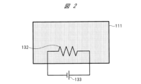
- FIG. 2 is a schematic diagram showing a sensor according to the first embodiment.
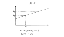
- FIG. 2 is an explanatory diagram for explaining the principle of the sensor in the first embodiment.
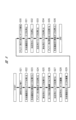
- 1 is a schematic diagram showing a system of an ion milling apparatus in a first embodiment.
- 4 is a flowchart showing a method for supplying liquid nitrogen in the first embodiment.
- FIG. 2 is a schematic diagram showing the ion milling apparatus during the supply of liquid nitrogen in the first embodiment.
- FIG. 2 is a schematic diagram showing the ion milling apparatus during the supply of liquid nitrogen in the first embodiment.
- 4 is a flowchart showing a method for discharging liquid nitrogen in the first embodiment.
- 1 is a schematic diagram showing an ion milling apparatus according to embodiment 1 during discharge of liquid nitrogen;
- the ion milling device 100 mainly comprises a sample chamber 101, a dewar 102, a tank 103, piping 104, a valve 105, a release valve 106, a safety valve 107, piping 108, a valve 109, a heater 110, an upper stage sensor 111, a middle stage sensor 112, a lower stage sensor 113, a pressure gauge 114, a release valve 115, a safety valve 116, piping 117, a valve 118, a heater 119, an upper stage sensor 120, a lower stage sensor 121, a pressure gauge 122, a movable mechanism 123, piping 124, a valve 125, piping 126, a valve 127, a heater 128, a release valve 129, a fixing part 130, and a cooling cable fixing part 131.
- the dewar 102 is provided to store liquid nitrogen 10.
- the tank 103 is provided to store liquid nitrogen 10 to be supplied to the inside of the dewar 102.
- the inside of the dewar 102 and the inside of the tank 103 are connected by a pipe 104.
- a valve 105 is provided on the pipe 104. When the valve 105 is open, the liquid nitrogen 10 is supplied from the inside of the tank 103 to the inside of the dewar 102 through the pipe 104.
- the capacity of the dewar 102 is, for example, 100 ml or more and 200 ml or less.
- the capacity of the tank 103 is sufficiently larger than the capacity of the dewar 102, for example, 4000 ml or more and 8000 ml or less.
- the inside of the dewar 102 and the inside of the tank 103 are connected by a pipe 124.
- the pipe 124 is provided on the bottom surface of the dewar 102 and on the lower part of the tank 103.
- a valve 125 is provided on the pipe 124. When the valve 125 is open, the liquid nitrogen 10 is discharged from the inside of the dewar 102 to the inside of the tank 103 through the pipe 124.
- the dewar 102 is provided with a release valve 106, a safety valve 107, and a pressure gauge 114.
- a release valve 106 By closing the release valve 106 or the safety valve 107, the inside of the dewar 102 is made airtight.
- a pressure gauge 114 By opening the release valve 106 or the safety valve 107, the inside of the dewar 102 is opened to the atmosphere.
- the pressure gauge 114 can measure the air pressure inside the dewar 102.
- a heater 110 is provided outside the dewar 102.
- the inside of the dewar 102 and the heater 110 are connected by piping 108.
- a valve 109 is provided on the piping 108. By driving the heater 110 with the valve 109 open, the heat from the heater 110 can be transferred to the inside of the dewar 102 via the piping 108.
- An upper level sensor 111, a middle level sensor 112, and a lower level sensor 113 are provided inside the dewar 102. Inside the dewar 102, the upper level sensor 111 is provided above the middle level sensor 112, and the lower level sensor 113 is provided below the middle level sensor 112.
- the upper level sensor 111, the middle level sensor, and the lower level sensor 113 are each liquid level sensors that can detect the liquid nitrogen 10 inside the dewar 102.
- Tank 103 is provided with release valve 115, safety valve 116, and pressure gauge 122.
- release valve 115 or safety valve 116 By closing release valve 115 or safety valve 116, the inside of tank 103 is made airtight.
- release valve 115 or safety valve 116 By opening release valve 115 or safety valve 116, the inside of tank 103 is opened to the atmosphere.
- Pressure gauge 122 can measure the air pressure inside tank 103.
- a heater 119 is provided on the outside of the tank 103.
- the inside of the tank 103 and the heater 119 are connected by a pipe 117.
- a valve 118 is provided on the pipe 117. By driving the heater 119 with the valve 118 open, the heat from the heater 119 can be transferred to the inside of the tank 103 via the pipe 117.
- An upper level sensor 120 and a lower level sensor 121 are provided inside the tank 103. Inside the tank 103, the upper level sensor 120 is provided above the lower level sensor 121.
- the upper level sensor 120 and the lower level sensor 121 are each liquid level sensors and can detect the liquid nitrogen 10 inside the tank 103.
- a movable mechanism 123 is provided below the tank 103.
- the movable mechanism 123 is provided to move the tank 103 in the vertical direction. The vertical position of the tank 103 is adjusted by the movable mechanism 123.
- the inside of the sample chamber 101 and the inside of the dewar 102 are connected by piping 126 for the cooling passage.
- the piping 126 is fixed by a fixing part 130 provided on the outer wall of the sample chamber 101, and is connected to a cooling cable fixing part 131 provided inside the sample chamber 101.
- the pipe 126 and the Dewar 102 have a double structure with an inner wall and an outer wall.
- a high vacuum is created between the inner wall and the outer wall, and the liquid nitrogen 10 can be held for a long time.
- a valve 127 is provided on the piping 126.
- the valve 127 is opened to supply liquid nitrogen 10 from inside the Dewar 102 to inside the sample chamber 101 via the piping 126.
- the heater 128 is provided adjacent to the pipe 126 and between the valve 127 and the sample chamber 101. By driving the heater 128, the heat from the heater 128 can be transferred to the inside of the pipe 126.
- a release valve 129 is provided in the pipe 126 located between the valve 127 and the sample chamber 101. By closing the release valve 129, the inside of the pipe 126 is made airtight. By opening the release valve 129, the inside of the pipe 126 is opened to the atmosphere.
- processing of a sample is carried out, which is to be observed with an electron microscope such as a scanning electron microscope or a transmission electron microscope.
- an ion gun capable of emitting an unfocused ion beam is provided inside the sample chamber 101. Processing of the sample is carried out while the sample is held in a holder.
- the sample may be, for example, a metal, a semiconductor, a glass, a ceramic, or a thermoplastic resin.
- the sample when the sample is a thermoplastic resin or a metallic material such as solder that undergoes a phase transformation at low temperatures, it is desirable to perform cooled ion milling.
- cooled ion milling liquid nitrogen 10 is supplied from inside the Dewar 102 to the inside of the sample chamber 101 during ion milling, and the cooling cable fixing part 131 is sufficiently cooled.
- the holder holding the sample is fixed to a copper wire extended from the cooling cable fixing part 131. Therefore, the sample is indirectly cooled by the liquid nitrogen 10 supplied from the Dewar 102.
- the upper sensor 111, the middle sensor 112, the lower sensor 113, the upper sensor 120, and the lower sensor 121 will be explained using Figures 2 and 3. Note that the upper sensor 111, the middle sensor 112, the lower sensor 113, the upper sensor 120, and the lower sensor 121 are sensors of the same structure, so the upper sensor 111 will be explained below as a representative.
- the upper sensor 111 includes a resistive element 132. Both ends of the resistive element 132 are electrically connected to a power source 133. The operating principle of the upper sensor 111 will be explained using FIG. 3.
- the temperature is T 0
- the resistance value of the resistive element 132 is R T0
- the resistance temperature coefficient is ⁇ T0
- the resistance value of the resistive element 132 is R T.
- This resistance value R T is expressed by the formula shown in Fig. 3. However, it is essential that the relationships ⁇ T0 > 0 and T - T 0 > 0 are satisfied.
- the upper sensor 111 determines whether or not liquid nitrogen 10 is present based on the amount of current flowing through the resistive element 132. Note that the amount of current described here is measured in units of "A.”
- the upper sensor 111 determines that it is in contact with the liquid nitrogen 10 and can detect the liquid nitrogen 10. Therefore, it can be determined that the liquid nitrogen level is located above the upper sensor 111 and that there is a sufficient amount of liquid nitrogen 10 remaining.
- the upper sensor 111 determines that it is far away from the liquid nitrogen 10 and cannot detect the liquid nitrogen 10. Therefore, it can be determined that the liquid level of the liquid nitrogen 10 is located below the upper sensor 111 and that the remaining amount of liquid nitrogen 10 is insufficient.
- the ion milling apparatus 100 includes a control unit 140.
- the control unit 140 is a processing device including a semiconductor device such as a CPU.
- the control unit 140 is electrically connected to and controls each valve, each release valve, each safety valve, each pressure gauge, each heater drive, movable mechanism, each sensor, and the ion gun.
- valves 105, 109, 118, 125, 127, the opening and closing operations of release valves 106, 115, 129, the opening and closing operations of safety valves 107, 116, the measurement operations of pressure gauges 114, 122, the driving of heaters 110, 119, 128, the adjustment operation of movable mechanism 123, the detection operations of sensors 111, 112, 113, 120, 121, and the ion beam irradiation of the ion gun in sample chamber 101 are controlled by control unit 140.
- the inside of the dewar 102 is filled with liquid nitrogen 10 so that the liquid level of the liquid nitrogen 10 is located at least above the middle stage sensor 112, and preferably above the upper stage sensor 111.
- the valves 105, 109, 118, and 125, the safety valves 107 and 116, and the release valve 129 are closed so as not to promote the movement of the liquid nitrogen 10.
- the release valves 106 and 115 are open.
- liquid nitrogen 10 is supplied from inside the dewar 102 to inside the sample chamber 101 via the pipe 126 by opening the valve 127.
- the liquid nitrogen 10 is supplied from inside the tank 103 to inside the dewar 102 by using the siphon effect. Therefore, the inside of the pipe 104 is filled with liquid nitrogen 10.
- the amount of liquid nitrogen 10 remaining inside the dewar 102 decreases depending on the time required for cooling ion milling. Therefore, it is necessary to replenish the liquid nitrogen 10 from inside the tank 103 to the inside of the dewar 102.
- step S1 the liquid nitrogen 10 is detected by the middle stage sensor 112 in the dewar 102.
- Step S1 is the starting point for the supply of liquid nitrogen 10 to the dewar 102.
- steps S2 and S3 are performed.
- step S2 the release valve 115 for the tank 103 is closed. This makes the inside of the tank 103 airtight.
- step S3 the supply valve 105 is opened. This allows the liquid nitrogen 10 to pass through the inside of the pipe 104.
- step S4 after steps S2 and S3, the supply of liquid nitrogen 10 begins. Due to the siphon effect, liquid nitrogen 10 is supplied from inside the tank 103 to inside the dewar 102 via the piping 104.
- step S5 the vertical position of the tank 103 is adjusted by the movable mechanism 123 so that the tank 103 rises as the supply of liquid nitrogen 10 begins. Since the potential energy of the liquid nitrogen 10 inside the tank 103 increases, supply by the siphon effect is promoted. Preferably, the vertical position of the tank 103 is adjusted so that the liquid level of the liquid nitrogen 10 inside the tank 103 is higher than the liquid level of the liquid nitrogen 10 inside the dewar 102.
- step S6 the upper sensor 120 of the tank 103 detects liquid nitrogen 10. If the upper sensor 120 does not detect liquid nitrogen 10 (NO), steps S7 and S8 are performed. If the upper sensor 120 detects liquid nitrogen 10 (YES), step S9 is performed.
- FIG. 7 shows steps S7 and S8.
- step S7 after it is confirmed that the release valve 115 for the tank 103 is closed, the pressurizing valve 118 is opened.
- step S8 the pressurizing heater 119 is driven. This causes the liquid nitrogen 10 inside the tank 103 to vaporize due to the heat from the heater 119, increasing the air pressure inside the tank 103 and creating an air pressure difference between the inside of the tank 103 and the inside of the dewar 102. This air pressure difference promotes the supply of liquid nitrogen 10 from the inside of the tank 103 to the inside of the dewar 102.
- the safety valve 116 opens the tank to the atmosphere. That is, when the pressure gauge 122 measures that the air pressure inside the tank 103 has reached a predetermined value or higher, the valve 118 is closed, the heater 119 is stopped, and the safety valve 116 is opened.
- step S9 the upper sensor 111 of the dewar 102 detects the liquid nitrogen 10.
- the upper sensor 111 detects the liquid nitrogen 10
- Steps from S10 onwards are steps for stopping the supply of liquid nitrogen 10.
- step S10 the upper sensor 120 of the tank 103 detects liquid nitrogen 10. If the upper sensor 120 does not detect liquid nitrogen 10 (NO), steps S11 and S12 are performed. If the upper sensor 120 detects liquid nitrogen 10 (YES), step S13 is performed.
- step S11 the heater 119 is stopped, and in step S12, the valve 118 is closed.
- step S13 the valve 105 is closed.
- step S14 the release valve 115 for the tank 103 is opened.
- step S15 the supply of liquid nitrogen 10 from the inside of the tank 103 to the inside of the dewar 102 is terminated.
- liquid nitrogen 10 when the remaining amount of liquid nitrogen 10 stored in the dewar 102 becomes low, liquid nitrogen 10 can be automatically supplied from the tank 103 to the dewar 102. Therefore, there is no need to manually resupply liquid nitrogen 10 to the inside of the dewar 102, and the processing time of the cooled ion milling can be extended. In addition, the remaining amount of liquid nitrogen 10 during the cooled ion milling can be secured without increasing the capacity of the dewar 102.
- the control unit 140 performs feedback control, and an instruction to replenish the liquid nitrogen 10 is displayed on the monitor of the ion milling device 100. The user can then replenish the liquid nitrogen 10 inside the tank 103.
- step S21 processing of the sample is completed inside the sample chamber 101.
- the valve 105 is closed and the supply of liquid nitrogen 10 from inside the tank 103 to inside the dewar 102 is stopped.
- step S22 a discharge operation is performed to discharge the liquid nitrogen 10 from inside the dewar 102 to inside the tank 103 via the pipe 124.
- step S22 the valve 127 for the cooling passage is closed. This stops the supply of liquid nitrogen 10 from inside the Dewar 102 to inside the sample chamber 101.
- step S23 the release valve 129 for the cooling passage is opened. This allows the liquid nitrogen 10 remaining in the pipe 124 to be discharged.
- step S24 the release valve 106 of the dewar 102 is closed. This makes the inside of the dewar 102 airtight.
- step S25 the discharge valve 125 is opened. This starts the discharge of liquid nitrogen 10 from inside the dewar 102 to inside the tank 103 via the pipe 124.
- step S26 the vertical position of the tank 103 is adjusted by the movable mechanism 123 so that the tank 103 descends. This allows gravity to act, making it easier for the liquid nitrogen 10 to move from inside the dewar 102 to inside the tank 103.
- step S27 the pressurizing valve 109 for the dewar 102 is opened.
- step S28 the heater 110 for pressurizing the dewar 102 is driven.
- the liquid nitrogen 10 inside the dewar 102 is vaporized by the heat from the heater 110, the air pressure inside the dewar 102 increases, and a pressure difference occurs between the inside of the dewar 102 and the inside of the tank 103. This pressure difference promotes the discharge of the liquid nitrogen 10 from the inside of the dewar 102 to the inside of the tank 103.
- the safety valve 107 opens to the atmosphere. That is, when the pressure gauge 114 measures that the air pressure inside the dewar 102 has reached a predetermined value or higher, the valve 109 is closed, the heater 110 is stopped, and the safety valve 107 is opened.
- step S29 the heater 128 for the cooling passage is driven.
- the liquid nitrogen 10 remaining in the pipe 126 located between the sample chamber 101 and the valve 127 is vaporized by the heat from the heater 128 and discharged from the release valve 129.
- the temperatures of the cooling passage fixing part 130 and the cooling cable fixing part 131 rise due to heat conduction through the piping 126.
- the temperature of the copper wire extended from the cooling cable fixing part 131 also rises, and the temperature of the holder fixed to the copper wire also rises.
- the temperature of the sample held in the holder also rises, and the sample can be removed after it has been brought to a state where it will not condense.
- step S30 the lower sensor 113 of the dewar 102 detects the liquid nitrogen 10.
- the lower sensor 113 does not detect the liquid nitrogen 10, it means that the liquid nitrogen 10 has been sufficiently discharged from inside the dewar 102.
- Steps S31 and onwards are steps for stopping the discharge operation of the liquid nitrogen 10.
- step S31 the heater 128 for the cooling passage is stopped.
- step S32 the heater 110 for pressurization is stopped.
- step S33 the valve 109 for pressurization is closed.
- step S34 the valve 125 for exhaust is closed.
- step S35 the release valve 106 of the dewar 102 is opened.
- step S36 the release valve 129 for the cooling passage is closed.
- the liquid nitrogen 10 inside the dewar 102 can be automatically discharged into the tank 103.
- liquid nitrogen 10 can be supplied from inside the tank 103 to inside the dewar 102 by the siphon effect.
- the supply valve 105 is opened, the release valve 115 of the tank 103 is closed, the pressurizing valve 118 is opened, and the pressurizing heater 119 is driven.
- This increases the air pressure inside the tank 103, creating an air pressure difference between the inside of the tank 103 and the inside of the dewar 102.
- This air pressure difference causes liquid nitrogen 10 to move from inside the tank 103 to inside the pipe 104, filling the inside of the pipe 104 with liquid nitrogen 10, and enabling the siphon effect to be achieved.
- the heater 119 of the tank 103 and the heater 110 of the dewar 102 may not be provided.
- the pressurization pipe 108 of the dewar 102 and the pressurization pipe 117 of the tank 103 are not formed into a double vacuum structure, and the pressurization valve 109 of the dewar 102 and the pressurization valve 118 of the tank 103 are opened while the liquid nitrogen in the pipes is constantly being encouraged to vaporize. This allows the vaporized liquid nitrogen to flow into the container, increasing the pressure in the dewar 102 and the tank 103.
Landscapes
- Chemical & Material Sciences (AREA)
- Analytical Chemistry (AREA)
- Physics & Mathematics (AREA)
- Engineering & Computer Science (AREA)
- Plasma & Fusion (AREA)
- Sampling And Sample Adjustment (AREA)
Abstract
Description
<イオンミリング装置の構造>
以下に図1~図4を用いて、実施の形態1におけるイオンミリング装置100について説明する。
図1に示されるように、通常の冷却イオンミリング時には、液体窒素10の液面が、少なくとも中段センサ112よりも上方に位置し、好ましくは上段センサ111よりも上方に位置するように、デュワー102の内部に液体窒素10が満たされている。また、液体窒素10の移動を促さないように、バルブ105、109、118、125と、安全弁107、116と、開放弁129とは、閉じてる。また、開放弁106、115は、開いている。
以下に図5~図7を用いて、デュワー102の内部に貯蔵された液体窒素10の残量が少なくなった際に、タンク103の内部からデュワー102の内部へ液体窒素10を供給するための供給方法について説明する。また、以下では基本的に、図5のフローチャートおよび図6の模式図を用いて説明するが、必要に応じて図7の模式図も用いる。
以下に図8および図9を用いて、デュワー102の内部からタンク103の内部へ液体窒素10を排出するための排出方法について説明する。
100 イオンミリング装置
101 試料室
102 デュワー
103 タンク
104 供給用の配管
105 供給用のバルブ
106 デュワー用の開放弁
107 デュワー用の安全弁
108 加圧用の配管
109 加圧用のバルブ
110 加圧用のヒータ
111 デュワー用の上段センサ
112 デュワー用の中段センサ
113 デュワー用の下段センサ
114 デュワー用の圧力計
115 タンク用の開放弁
116 タンク用の安全弁
117 加圧用の配管
118 加圧用のバルブ
119 加圧用のヒータ
120 タンク用の上段センサ
121 タンク用の下段センサ
122 タンク用の圧力計
123 タンク用の可動機構
124 排出用の配管
125 排出用のバルブ
126 冷却通路用の配管
127 冷却通路用のバルブ
128 冷却通路用のヒータ
129 冷却通路用の開放弁
130 冷却通路用の固定部
131 冷却ケーブル固定部
132 抵抗素子
133 電源
140 制御ユニット
Claims (14)
- 液体窒素を貯蔵するためのデュワーと、
前記デュワーの内部に設けられ、且つ、前記デュワーの内部における前記液体窒素を検知できる第1センサと、
前記デュワーの内部へ供給される前記液体窒素を貯蔵するためのタンクと、
前記デュワーの内部および前記タンクの内部を繋ぐ第1配管と、
前記第1配管に設けられた第1バルブと、
前記第1センサおよび前記第1バルブを制御する制御ユニットと、
を備え、
前記第1センサが前記液体窒素を検知しなかった際に、前記第1バルブを開けることで、前記液体窒素が、前記第1配管を介して前記タンクの内部から前記デュワーの内部へ供給される、イオンミリング装置。 - 請求項1に記載のイオンミリング装置において、
前記第1センサは、抵抗素子を含み、
前記抵抗素子に流れる電流の量は、温度の変化に応じて変化し、
前記電流の量によって、前記第1センサは、前記液体窒素の存在の有無を判定する、イオンミリング装置。 - 請求項1に記載のイオンミリング装置において、
前記デュワーの内部において前記第1センサよりも上方に設けられ、且つ、前記デュワーの内部における前記液体窒素を検知できる第2センサを更に備え、
前記第2センサは、前記制御ユニットによって制御され、
前記第2センサが前記液体窒素を検知した際に、前記第1バルブを閉じることで、前記タンクの内部から前記デュワーの内部への前記液体窒素の供給が停止する、イオンミリング装置。 - 請求項1に記載のイオンミリング装置において、
前記タンクを上下方向へ移動させるための可動機構を更に備え、
前記可動機構は、前記制御ユニットによって制御され、
前記第1センサが前記液体窒素を検知しなかった際に、前記タンクの内部の前記液体窒素の液面の位置が前記デュワーの内部の前記液体窒素の液面の位置よりも高くなるように、前記可動機構によって前記タンクの上下位置を調整する、イオンミリング装置。 - 請求項1に記載のイオンミリング装置において、
前記タンクの内部に設けられ、且つ、前記タンクの内部における前記液体窒素を検知できる第3センサと、
前記タンクの外部に設けられた第1ヒータと、
前記タンクの内部および前記第1ヒータを繋ぐ第2配管と、
前記第2配管に設けられた第2バルブと、
前記タンクに設けられた第1開放弁と、
前記タンクに設けられ、且つ、前記タンクの内部の気圧を計測するための第1圧力計と、
を更に備え、
前記第3センサ、前記第1ヒータ、前記第2バルブ、前記第1開放弁および前記第1圧力計は、前記制御ユニットによって制御され、
前記第3センサが前記液体窒素を検知しなかった際に、前記第1開放弁を閉じ、前記第2バルブを開き、且つ、前記第1ヒータを駆動することで、前記第1ヒータからの熱量によって前記タンクの内部の前記液体窒素が気化し、前記タンクの内部の気圧が上昇し、前記タンクの内部および前記デュワーの内部の気圧差によって、前記タンクの内部から前記デュワーの内部への前記液体窒素の供給が促進される、イオンミリング装置。 - 請求項5に記載のイオンミリング装置において、
前記デュワーの内部において前記第1センサよりも上方に設けられ、且つ、前記デュワーの内部における前記液体窒素を検知できる第2センサを更に備え、
前記第2センサは、前記制御ユニットによって制御され、
前記第2センサが前記液体窒素を検知した際に、前記第1ヒータの駆動を停止させ、前記第2バルブを閉じ、且つ、前記第1バルブを閉じることで、前記タンクの内部から前記デュワーの内部への前記液体窒素の供給が停止する、イオンミリング装置。 - 請求項5に記載のイオンミリング装置において、
前記タンクに設けられた第1安全弁を更に備え、
前記第1安全弁は、前記制御ユニットによって制御され、
前記タンクの内部の気圧が所定値以上になったことを、前記第1圧力計が計測した際に、前記第1バルブを閉じ、前記第1ヒータを停止させ、且つ、前記第1安全弁を開ける、イオンミリング装置。 - 請求項1に記載のイオンミリング装置において、
前記デュワーの内部および前記タンクの内部を繋ぐ第3配管と、
前記第3配管に設けられた第3バルブと、
を更に備え、
前記第3バルブは、前記制御ユニットによって制御され、
前記第3配管を介して前記デュワーの内部から前記タンクの内部へ前記液体窒素を排出する際に、前記第1バルブを閉じ、且つ、前記第3バルブを開ける、イオンミリング装置。 - 請求項8に記載のイオンミリング装置において、
前記デュワーの内部において前記第1センサよりも下方に設けられ、且つ、前記デュワーの内部における前記液体窒素を検知できる第4センサを更に備え、
前記第4センサは、前記制御ユニットによって制御され、
前記第4センサが前記液体窒素を検知しなかった際に、前記第3バルブを閉じることで、前記デュワーの内部から前記タンクの内部への前記液体窒素の排出が停止する、イオンミリング装置。 - 請求項8に記載のイオンミリング装置において、
前記タンクを上下方向へ移動させるための可動機構を更に備え、
前記可動機構は、前記制御ユニットによって制御され、
前記第3配管を介して前記デュワーの内部から前記タンクの内部へ前記液体窒素を排出する際に、前記タンクが下降するように、前記可動機構によって前記タンクの上下位置を調整する、イオンミリング装置。 - 請求項8に記載のイオンミリング装置において、
前記デュワーの外部に設けられた第2ヒータと、
前記デュワーの内部および前記第2ヒータを繋ぐ第4配管と、
前記第4配管に設けられた第4バルブと、
前記デュワーに設けられた第2開放弁と、
前記デュワーに設けられ、且つ、前記デュワーの内部の気圧を計測するための第2圧力計と、
を更に備え、
前記第2ヒータ、前記第4バルブ、前記第2開放弁および前記第2圧力計は、前記制御ユニットによって制御され、
前記第3配管を介して前記デュワーの内部から前記タンクの内部へ前記液体窒素を排出する際に、前記第2開放弁を閉じ、前記第4バルブを開き、且つ、前記第2ヒータを駆動することで、前記第2ヒータからの熱量によって前記デュワーの内部の前記液体窒素が気化し、前記デュワーの内部の気圧が上昇し、前記デュワーの内部および前記タンクの内部の気圧差によって、前記デュワーの内部から前記タンクの内部への前記液体窒素の排出が促進される、イオンミリング装置。 - 請求項11に記載のイオンミリング装置において、
前記デュワーに設けられた第2安全弁を更に備え、
前記第2安全弁は、前記制御ユニットによって制御され、
前記デュワーの内部の気圧が所定値以上になったことを、前記第2圧力計が計測した際に、前記第4バルブを閉じ、前記第2ヒータを停止させ、且つ、前記第2安全弁を開ける、イオンミリング装置。 - 請求項8に記載のイオンミリング装置において、
試料の加工を行うための試料室と、
前記デュワーの内部および前記試料室の内部を繋ぐ第5配管と、
前記第5配管に設けられた第5バルブと、
を更に備え、
前記第5バルブは、前記制御ユニットによって制御され、
前記試料室の内部において前記試料の加工が行われている際に、前記第5バルブを開けることで、前記液体窒素が、前記第5配管を介して前記デュワーの内部から前記試料室の内部へ供給される、イオンミリング装置。 - 請求項13に記載のイオンミリング装置において、
前記第5配管に隣接して設けられ、且つ、前記第5バルブと前記試料室との間に設けられた第3ヒータと、
前記第5バルブと前記試料室との間に位置する前記第5配管に設けられた第3開放弁と、
を更に備え、
前記第3ヒータおよび前記第3開放弁は、前記制御ユニットによって制御され、
前記試料の加工が終了した後、前記第3配管を介して前記デュワーの内部から前記タンクの内部へ前記液体窒素を排出する際に、前記第5バルブを閉じ、前記第3開放弁を開き、且つ、前記第3ヒータを駆動させることで、前記第5配管に残留していた前記液体窒素は、前記第3ヒータからの熱量によって気化され、前記第3開放弁から排出される、イオンミリング装置。
Priority Applications (2)
| Application Number | Priority Date | Filing Date | Title |
|---|---|---|---|
| PCT/JP2023/012017 WO2024201614A1 (ja) | 2023-03-24 | 2023-03-24 | イオンミリング装置 |
| JP2025509250A JPWO2024201614A1 (ja) | 2023-03-24 | 2023-03-24 |
Applications Claiming Priority (1)
| Application Number | Priority Date | Filing Date | Title |
|---|---|---|---|
| PCT/JP2023/012017 WO2024201614A1 (ja) | 2023-03-24 | 2023-03-24 | イオンミリング装置 |
Publications (1)
| Publication Number | Publication Date |
|---|---|
| WO2024201614A1 true WO2024201614A1 (ja) | 2024-10-03 |
Family
ID=92903562
Family Applications (1)
| Application Number | Title | Priority Date | Filing Date |
|---|---|---|---|
| PCT/JP2023/012017 Ceased WO2024201614A1 (ja) | 2023-03-24 | 2023-03-24 | イオンミリング装置 |
Country Status (2)
| Country | Link |
|---|---|
| JP (1) | JPWO2024201614A1 (ja) |
| WO (1) | WO2024201614A1 (ja) |
Citations (6)
| Publication number | Priority date | Publication date | Assignee | Title |
|---|---|---|---|---|
| JPS5862080U (ja) * | 1981-10-21 | 1983-04-26 | 昭和電線電纜株式会社 | 冷媒自動供給装置 |
| JPH04114429U (ja) * | 1991-03-15 | 1992-10-08 | 岩谷産業株式会社 | 機器冷却用液化ガス貯蔵容器への液化ガス自動供給装置 |
| JPH04301552A (ja) * | 1991-03-28 | 1992-10-26 | Shimadzu Corp | 熱分析装置用加熱炉及び温度制御方法 |
| WO2014199737A1 (ja) * | 2013-06-10 | 2014-12-18 | 株式会社 日立ハイテクノロジーズ | イオンミリング装置 |
| CN208367555U (zh) * | 2018-06-20 | 2019-01-11 | 福建省银丰干细胞工程有限公司 | 程序降温仪 |
| JP2020092053A (ja) * | 2018-12-07 | 2020-06-11 | 日本電子株式会社 | 真空冷却装置及びイオンミリング装置 |
Family Cites Families (3)
| Publication number | Priority date | Publication date | Assignee | Title |
|---|---|---|---|---|
| EP2610888B1 (en) * | 2009-06-18 | 2016-11-02 | Carl Zeiss Microscopy, LLC | Cooled charged particle systems and methods |
| JP3205076U (ja) * | 2016-02-08 | 2016-07-07 | 東京エレクトロン株式会社 | 処理液供給装置 |
| JP2019147069A (ja) * | 2016-07-05 | 2019-09-05 | 速緒 伊藤 | 減溶化装置 |
-
2023
- 2023-03-24 WO PCT/JP2023/012017 patent/WO2024201614A1/ja not_active Ceased
- 2023-03-24 JP JP2025509250A patent/JPWO2024201614A1/ja active Pending
Patent Citations (6)
| Publication number | Priority date | Publication date | Assignee | Title |
|---|---|---|---|---|
| JPS5862080U (ja) * | 1981-10-21 | 1983-04-26 | 昭和電線電纜株式会社 | 冷媒自動供給装置 |
| JPH04114429U (ja) * | 1991-03-15 | 1992-10-08 | 岩谷産業株式会社 | 機器冷却用液化ガス貯蔵容器への液化ガス自動供給装置 |
| JPH04301552A (ja) * | 1991-03-28 | 1992-10-26 | Shimadzu Corp | 熱分析装置用加熱炉及び温度制御方法 |
| WO2014199737A1 (ja) * | 2013-06-10 | 2014-12-18 | 株式会社 日立ハイテクノロジーズ | イオンミリング装置 |
| CN208367555U (zh) * | 2018-06-20 | 2019-01-11 | 福建省银丰干细胞工程有限公司 | 程序降温仪 |
| JP2020092053A (ja) * | 2018-12-07 | 2020-06-11 | 日本電子株式会社 | 真空冷却装置及びイオンミリング装置 |
Also Published As
| Publication number | Publication date |
|---|---|
| JPWO2024201614A1 (ja) | 2024-10-03 |
Similar Documents
| Publication | Publication Date | Title |
|---|---|---|
| JP4877434B2 (ja) | ガス充填装置及びガス充填方法 | |
| JP6338755B2 (ja) | 真空引き可能なキャビティを伴う、真空容器と冷却対象物とを有するクライオスタット装置 | |
| KR20220091594A (ko) | 고온 초전도 케이블들의 금속을 채우기 위한 공정들, 시스템들 및 장치들 | |
| KR101754356B1 (ko) | 증발원, 증착물질 공급장치, 및 이를 포함하는 증착장치 | |
| KR20110034420A (ko) | 용융금속 공급장치 | |
| US4283935A (en) | Device for measuring thermal conductivity of liquid | |
| KR101713112B1 (ko) | 연속 충진이 가능한 증착물질 공급장치 | |
| TWI473950B (zh) | 液化氣體供應裝置及方法 | |
| KR102558443B1 (ko) | 성막 장치 | |
| JP4462989B2 (ja) | 蒸着装置 | |
| JP6124367B2 (ja) | 低温用比較校正装置 | |
| US10481222B2 (en) | Fluid path insert for a cryogenic cooling system | |
| KR101936308B1 (ko) | 박막증착장치 | |
| JP6122231B1 (ja) | 液化ガス供給方法 | |
| US20130118184A1 (en) | Cooled charged particle systems and methods | |
| KR102964289B1 (ko) | 온도 제어 장치, 기판 처리 장치 및 액량 제어 방법 | |
| WO2010134472A1 (ja) | 水素ガス供給装置 | |
| JP6217324B2 (ja) | 低圧鋳造用溶湯保持炉の注湯槽の湯面高さ制御方法 | |
| KR20220165193A (ko) | 제어 방법 및 제어 장치 | |
| JP6570567B2 (ja) | 蒸着装置及び蒸着方法 | |
| US20250164102A1 (en) | Liquid material vaporization apparatus and operation setting method thereof | |
| JPH07221091A (ja) | 薄膜形成装置の原料供給量制御方法 | |
| JPH0792008A (ja) | 液体金属用液面計校正装置 | |
| US20250327726A1 (en) | Superfluid helium based liquid thermal switch for a dynamic nuclear polarization system | |
| KR102738703B1 (ko) | 액체 수위측정장치 및 방법 |
Legal Events
| Date | Code | Title | Description |
|---|---|---|---|
| 121 | Ep: the epo has been informed by wipo that ep was designated in this application |
Ref document number: 23930255 Country of ref document: EP Kind code of ref document: A1 |
|
| DPE1 | Request for preliminary examination filed after expiration of 19th month from priority date (pct application filed from 20040101) | ||
| ENP | Entry into the national phase |
Ref document number: 2025509250 Country of ref document: JP Kind code of ref document: A |
|
| WWE | Wipo information: entry into national phase |
Ref document number: 2025509250 Country of ref document: JP |
|
| NENP | Non-entry into the national phase |
Ref country code: DE |
|
| 122 | Ep: pct application non-entry in european phase |
Ref document number: 23930255 Country of ref document: EP Kind code of ref document: A1 |