WO2024201599A1 - 空気調和機 - Google Patents
空気調和機 Download PDFInfo
- Publication number
- WO2024201599A1 WO2024201599A1 PCT/JP2023/011930 JP2023011930W WO2024201599A1 WO 2024201599 A1 WO2024201599 A1 WO 2024201599A1 JP 2023011930 W JP2023011930 W JP 2023011930W WO 2024201599 A1 WO2024201599 A1 WO 2024201599A1
- Authority
- WO
- WIPO (PCT)
- Prior art keywords
- unit
- indoor
- refrigerant
- power supply
- outdoor
- Prior art date
- Legal status (The legal status is an assumption and is not a legal conclusion. Google has not performed a legal analysis and makes no representation as to the accuracy of the status listed.)
- Ceased
Links
Images






Classifications
-
- F—MECHANICAL ENGINEERING; LIGHTING; HEATING; WEAPONS; BLASTING
- F24—HEATING; RANGES; VENTILATING
- F24F—AIR-CONDITIONING; AIR-HUMIDIFICATION; VENTILATION; USE OF AIR CURRENTS FOR SCREENING
- F24F11/00—Control or safety arrangements
- F24F11/30—Control or safety arrangements for purposes related to the operation of the system, e.g. for safety or monitoring
- F24F11/32—Responding to malfunctions or emergencies
- F24F11/36—Responding to malfunctions or emergencies to leakage of heat-exchange fluid
-
- F—MECHANICAL ENGINEERING; LIGHTING; HEATING; WEAPONS; BLASTING
- F24—HEATING; RANGES; VENTILATING
- F24F—AIR-CONDITIONING; AIR-HUMIDIFICATION; VENTILATION; USE OF AIR CURRENTS FOR SCREENING
- F24F11/00—Control or safety arrangements
- F24F11/30—Control or safety arrangements for purposes related to the operation of the system, e.g. for safety or monitoring
- F24F11/32—Responding to malfunctions or emergencies
-
- F—MECHANICAL ENGINEERING; LIGHTING; HEATING; WEAPONS; BLASTING
- F25—REFRIGERATION OR COOLING; COMBINED HEATING AND REFRIGERATION SYSTEMS; HEAT PUMP SYSTEMS; MANUFACTURE OR STORAGE OF ICE; LIQUEFACTION SOLIDIFICATION OF GASES
- F25B—REFRIGERATION MACHINES, PLANTS OR SYSTEMS; COMBINED HEATING AND REFRIGERATION SYSTEMS; HEAT PUMP SYSTEMS
- F25B13/00—Compression machines, plants or systems, with reversible cycle
-
- F—MECHANICAL ENGINEERING; LIGHTING; HEATING; WEAPONS; BLASTING
- F25—REFRIGERATION OR COOLING; COMBINED HEATING AND REFRIGERATION SYSTEMS; HEAT PUMP SYSTEMS; MANUFACTURE OR STORAGE OF ICE; LIQUEFACTION SOLIDIFICATION OF GASES
- F25B—REFRIGERATION MACHINES, PLANTS OR SYSTEMS; COMBINED HEATING AND REFRIGERATION SYSTEMS; HEAT PUMP SYSTEMS
- F25B41/00—Fluid-circulation arrangements
- F25B41/20—Disposition of valves, e.g. of on-off valves or flow control valves
- F25B41/24—Arrangement of shut-off valves for disconnecting a part of the refrigerant cycle, e.g. an outdoor part
-
- F—MECHANICAL ENGINEERING; LIGHTING; HEATING; WEAPONS; BLASTING
- F25—REFRIGERATION OR COOLING; COMBINED HEATING AND REFRIGERATION SYSTEMS; HEAT PUMP SYSTEMS; MANUFACTURE OR STORAGE OF ICE; LIQUEFACTION SOLIDIFICATION OF GASES
- F25B—REFRIGERATION MACHINES, PLANTS OR SYSTEMS; COMBINED HEATING AND REFRIGERATION SYSTEMS; HEAT PUMP SYSTEMS
- F25B49/00—Arrangement or mounting of control or safety devices
- F25B49/02—Arrangement or mounting of control or safety devices for compression type machines, plants or systems
-
- F—MECHANICAL ENGINEERING; LIGHTING; HEATING; WEAPONS; BLASTING
- F25—REFRIGERATION OR COOLING; COMBINED HEATING AND REFRIGERATION SYSTEMS; HEAT PUMP SYSTEMS; MANUFACTURE OR STORAGE OF ICE; LIQUEFACTION SOLIDIFICATION OF GASES
- F25B—REFRIGERATION MACHINES, PLANTS OR SYSTEMS; COMBINED HEATING AND REFRIGERATION SYSTEMS; HEAT PUMP SYSTEMS
- F25B2313/00—Compression machines, plants or systems with reversible cycle not otherwise provided for
- F25B2313/007—Compression machines, plants or systems with reversible cycle not otherwise provided for three pipes connecting the outdoor side to the indoor side with multiple indoor units
-
- F—MECHANICAL ENGINEERING; LIGHTING; HEATING; WEAPONS; BLASTING
- F25—REFRIGERATION OR COOLING; COMBINED HEATING AND REFRIGERATION SYSTEMS; HEAT PUMP SYSTEMS; MANUFACTURE OR STORAGE OF ICE; LIQUEFACTION SOLIDIFICATION OF GASES
- F25B—REFRIGERATION MACHINES, PLANTS OR SYSTEMS; COMBINED HEATING AND REFRIGERATION SYSTEMS; HEAT PUMP SYSTEMS
- F25B2313/00—Compression machines, plants or systems with reversible cycle not otherwise provided for
- F25B2313/023—Compression machines, plants or systems with reversible cycle not otherwise provided for using multiple indoor units
- F25B2313/0231—Compression machines, plants or systems with reversible cycle not otherwise provided for using multiple indoor units with simultaneous cooling and heating
-
- F—MECHANICAL ENGINEERING; LIGHTING; HEATING; WEAPONS; BLASTING
- F25—REFRIGERATION OR COOLING; COMBINED HEATING AND REFRIGERATION SYSTEMS; HEAT PUMP SYSTEMS; MANUFACTURE OR STORAGE OF ICE; LIQUEFACTION SOLIDIFICATION OF GASES
- F25B—REFRIGERATION MACHINES, PLANTS OR SYSTEMS; COMBINED HEATING AND REFRIGERATION SYSTEMS; HEAT PUMP SYSTEMS
- F25B2313/00—Compression machines, plants or systems with reversible cycle not otherwise provided for
- F25B2313/027—Compression machines, plants or systems with reversible cycle not otherwise provided for characterised by the reversing means
- F25B2313/02732—Compression machines, plants or systems with reversible cycle not otherwise provided for characterised by the reversing means using two three-way valves
-
- F—MECHANICAL ENGINEERING; LIGHTING; HEATING; WEAPONS; BLASTING
- F25—REFRIGERATION OR COOLING; COMBINED HEATING AND REFRIGERATION SYSTEMS; HEAT PUMP SYSTEMS; MANUFACTURE OR STORAGE OF ICE; LIQUEFACTION SOLIDIFICATION OF GASES
- F25B—REFRIGERATION MACHINES, PLANTS OR SYSTEMS; COMBINED HEATING AND REFRIGERATION SYSTEMS; HEAT PUMP SYSTEMS
- F25B2500/00—Problems to be solved
- F25B2500/22—Preventing, detecting or repairing leaks of refrigeration fluids
- F25B2500/221—Preventing leaks from developing
-
- F—MECHANICAL ENGINEERING; LIGHTING; HEATING; WEAPONS; BLASTING
- F25—REFRIGERATION OR COOLING; COMBINED HEATING AND REFRIGERATION SYSTEMS; HEAT PUMP SYSTEMS; MANUFACTURE OR STORAGE OF ICE; LIQUEFACTION SOLIDIFICATION OF GASES
- F25B—REFRIGERATION MACHINES, PLANTS OR SYSTEMS; COMBINED HEATING AND REFRIGERATION SYSTEMS; HEAT PUMP SYSTEMS
- F25B2600/00—Control issues
- F25B2600/25—Control of valves
- F25B2600/2519—On-off valves
-
- F—MECHANICAL ENGINEERING; LIGHTING; HEATING; WEAPONS; BLASTING
- F25—REFRIGERATION OR COOLING; COMBINED HEATING AND REFRIGERATION SYSTEMS; HEAT PUMP SYSTEMS; MANUFACTURE OR STORAGE OF ICE; LIQUEFACTION SOLIDIFICATION OF GASES
- F25B—REFRIGERATION MACHINES, PLANTS OR SYSTEMS; COMBINED HEATING AND REFRIGERATION SYSTEMS; HEAT PUMP SYSTEMS
- F25B49/00—Arrangement or mounting of control or safety devices
- F25B49/005—Arrangement or mounting of control or safety devices of safety devices
Definitions
- An embodiment of the present invention relates to an air conditioner equipped with an emergency power supply device that shuts off the refrigerant piping using a shutoff valve unit in the event of a power outage.
- an air conditioner When an air conditioner detects a refrigerant leak, it has the shutoff valve unit shut off the refrigerant piping to prevent the leak from spreading.
- the unit For safety in the event of a power outage, the unit is equipped with an emergency power supply unit that supplies power to the shutoff valve unit.
- the emergency power supply unit functions as a backup power source in emergencies by storing electricity in storage components such as capacitors and secondary batteries mounted on the board.
- an air conditioner is provided that can prevent the spread of damage when a power storage component provided in an emergency power supply device fails.
- the air conditioner of the embodiment comprises an outdoor unit equipped with an outdoor expansion valve, an outdoor heat exchanger, a four-way valve, and a compressor, a plurality of indoor units equipped with an indoor heat exchanger and an indoor expansion valve that adjusts the amount of refrigerant flowing through the indoor heat exchanger, refrigerant piping connecting the outdoor unit and the plurality of indoor units, a shutoff valve unit disposed on the refrigerant piping and incorporating one or more shutoff mechanisms capable of shutting off the flow of refrigerant circulating between the outdoor unit and the indoor units, and an emergency power supply device disposed in an electrical component box made of sheet metal and causing the shutoff mechanism to shut off the power in the event of a power outage, the electrical component box being disposed in the shutoff valve unit.
- FIG. 1 is a diagram showing a first embodiment, with a portion of an air conditioner omitted, illustrating a state in which an outdoor unit and an indoor unit are connected via a cooling/heating switching unit of a shutoff valve device.
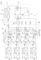
- FIG. 2 shows the overall configuration of the air conditioner.
- FIG. 3 is a functional block diagram showing the operation of the shutoff valve unit under normal conditions.
- FIG. 4 is a functional block diagram showing the operation of the shutoff valve cooling unit during a power outage.
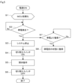
- FIG. 5 is a flowchart showing the system operation of the air conditioner when a power outage occurs.
- FIG. 6 is a perspective view showing the external appearance of the control valve housing and the cooling/heating switching unit.
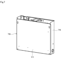
- FIG. 7 is a perspective view showing the appearance of the shutoff valve unit.
- FIG. 1 is a diagram showing a first embodiment, with a portion of an air conditioner omitted, illustrating a state in which an outdoor unit and an indoor unit are connected via a cooling/heating switching unit of a
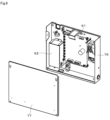
- FIG. 8 is an exploded perspective view showing the appearance of the shutoff valve unit.
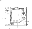
- FIG. 9 is a front view showing the inside of the shutoff valve unit with the lid removed.
- Fig. 10 is an exploded perspective view showing the external appearance of the emergency power supply device.
- FIG. 11 is a perspective view showing the appearance of the emergency power supply device.
- FIG. 12 shows the second embodiment, with a portion of the air conditioner omitted to show a state in which the outdoor unit and the indoor unit are connected via a shutoff valve unit.
- FIG. 13 is a perspective view showing the appearance of the control valve housing and the shutoff valve unit.
- the air conditioner 1 shown in Fig. 2 is a multi-type air conditioner that has multiple indoor units for one outdoor unit and is capable of full heating operation, full cooling operation, and simultaneous heating and cooling operation.
- Full heating operation is an operation mode in which all indoor units perform heating operation.
- Full cooling operation is an operation mode in which all indoor units perform cooling operation.
- Simultaneous heating and cooling operation is an operation mode in which some indoor units perform cooling operation and some indoor units perform heating operation.
- full heating operation, full cooling operation, and simultaneous heating and cooling operation may be collectively referred to as air conditioning operation.
- the air conditioner 1 is configured so that multiple indoor units 201, 202, 203, 204 can be operated by one outdoor unit 10.
- the air conditioner 1 is equipped with, for example, one outdoor unit 10, multiple indoor units 201-204, and a multi-port shutoff valve unit 40, which constitute one refrigeration cycle capable of circulating refrigerant.
- the outdoor unit 10 and the multi-port shutoff valve unit 40 are connected by a liquid side refrigerant pipe L, a gas side refrigerant pipe GD, and a gas side refrigerant pipe GS.
- the multi-port shutoff valve unit 40 and each of the indoor units 201-204 are connected by multiple liquid side refrigerant pipes L1-L4 and multiple gas side refrigerant pipes G1-G4.
- the gas side refrigerant pipe GD corresponds to the discharge gas pipe through which mainly high-pressure gas refrigerant flows
- the gas side refrigerant pipe GS corresponds to the suction gas pipe through which low-pressure gas refrigerant flows.
- high-pressure gas refrigerant and low-pressure gas refrigerant will be referred to simply as “high-pressure gas” and “low-pressure gas”, respectively.
- multi-port means that the shutoff valve unit has multiple port pairs for connecting indoor units.
- the multi-port shutoff valve unit 40 may be simply referred to as the shutoff valve unit 40.
- the shutoff valve unit 40 will be described as an example having four port pairs to connect four indoor units.
- the outdoor unit 10 is installed outdoors.
- the outdoor unit 10 has an outdoor heat exchanger 11, an outdoor blower 12, an outdoor expansion valve 13, a compressor 14, a first switching valve 15, and a second switching valve 16.
- the outdoor heat exchanger 11 has a function of exchanging heat between the refrigerant passing through the outdoor heat exchanger 11 and the outside air.
- the outdoor blower 12 has a function of promoting heat exchange in the outdoor heat exchanger 11 by blowing air to the outdoor heat exchanger 11.
- a slightly flammable or flammable refrigerant is used as the refrigerant in the refrigeration cycle. In this embodiment, for example, a slightly flammable R32 is used as the refrigerant.
- the outdoor expansion valve 13 is connected to the liquid side refrigerant pipe L that runs from the outdoor unit 10 to the indoor units 201-204.
- the outdoor expansion valve 13 has the function of reducing the pressure of the refrigerant by adjusting the flow path width of the refrigerant passing through the outdoor expansion valve 13, and adjusting the flow rate and pressure of the refrigerant flowing out of the outdoor heat exchanger 11 or flowing into the outdoor heat exchanger 11.
- the outdoor expansion valve 13 can be configured, for example, as an electronic expansion valve that is driven by an electrical signal from a micro control unit (MCU) (not shown) provided in the control unit of the outdoor unit 10.
- MCU micro control unit
- the first and second switching valves 15 and 16 have the function of switching the flow direction of the refrigerant in the refrigeration cycle, i.e., the direction in which the refrigerant discharged from the compressor 14 flows.
- the first and second switching valves 15 and 16 are, for example, four-way valves that are driven by receiving an electrical signal, but multiple valves other than four-way valves may be combined as long as the same refrigerant flow can be formed.
- the compressor 14 compresses and discharges the refrigerant flowing through the refrigeration cycle. Depending on the switching state of the first switching valve 15 and the second switching valve 16, the compressor 14 either sucks in the refrigerant on the outdoor heat exchanger 11 side and discharges the sucked in refrigerant to the shutoff valve unit 40 side, or sucks in the refrigerant on the shutoff valve unit 40 side and discharges the sucked in refrigerant to the outdoor heat exchanger 11 side.
- Each of the indoor units 201-204 is installed in a room that is the subject of air conditioning operation.
- Each of the indoor units 201-204 has an indoor heat exchanger 21, an indoor blower 22, an indoor expansion valve 23, and a leak detection sensor 24.
- each of the indoor units 201-204 can basically have the same configuration, the performance of the indoor heat exchanger 21, the indoor expansion valve 23, the indoor blower 22, and the leak detection sensor 24 can be changed as appropriate depending on the volume of the space in which they are installed.
- the indoor heat exchanger 21 exchanges heat between the refrigerant passing through the interior of the indoor heat exchanger 21 and the air in the room in which the indoor units 201-204 are installed.
- the indoor heat exchanger 21 is connected to the outdoor heat exchanger 11 and the compressor 14, and is configured so that the refrigerant can circulate between the outdoor heat exchanger 11, the indoor heat exchanger 21, and the compressor 14.
- the indoor blower 22 has the function of promoting heat exchange in the indoor heat exchanger 21 by blowing air to the indoor heat exchanger 21, and supplying air whose temperature has been adjusted by the indoor heat exchanger 21 into the room.
- the indoor expansion valve 23 has the function of adjusting the flow path width of the refrigerant passing through the indoor expansion valve 23 and controlling the amount of refrigerant flowing through it.
- the indoor expansion valve 23 can be configured as an electronic expansion valve that is driven by receiving an electrical signal from the MCU provided in the indoor control unit of each of the indoor units 201 to 204, for example.
- Each of the indoor units 201-204 has an indoor control unit (not shown).
- the shutoff valve units 40 also have a control unit (not shown in detail) that includes an MCU.
- the outdoor control unit of the outdoor unit 10, the indoor control units of the indoor units 201-204, and the control unit (not shown) of the shutoff valve unit 40 are connected to each other by communication lines and exchange various types of information.
- the leak detection sensor 24 has the function of detecting refrigerant leakage in each of the indoor units 201-204.
- the leak detection sensor 24 may be incorporated in each of the indoor units 201-204, or may be installed independently as a leak detection sensor unit in the indoor space of each room in which the indoor units 201-204 are installed. In the case of this embodiment, the leak detection sensor 24 is provided in each of the indoor units 201-204.
- the leak detection sensor 24 can be configured, for example, as a semiconductor gas sensor.
- the leak detection sensor 24 has the ability to detect the refrigerant sealed in the refrigeration cycle, in this case R32.
- the leak detection sensor 24 outputs an electrical signal that changes linearly depending on the concentration of the refrigerant, for example, for a refrigerant of about 300 to 30,000 ppm in the air, and when this detected concentration exceeds a predetermined value, it notifies the corresponding indoor unit 201-204 and outdoor unit 10 that a refrigerant leak has occurred.
- the shutoff valve unit 40 is provided between the outdoor unit 10 and each of the indoor units 201-204. That is, the outdoor unit 10 and each of the indoor units 201-204 are connected via the shutoff valve unit 40.
- the shutoff valve unit 40 has four cooling/heating switching sections 41-44 corresponding to the multiple indoor units 201-204, and a multi-port liquid-side control valve 45.
- the multi-port liquid-side control valve 45 may be simply referred to as the control valve 45.
- the cooling/heating switching units 41 to 44 each have a multi-port gas control valve 411 and 412, 421 and 422, 431 and 432, and 441 and 442.
- the multi-port gas control valves are also simply referred to as "control valves.”
- the control valves 411 and 412, 421 and 422, 431 and 432, and 441 and 442 are provided on the gas side refrigerant pipes 531 and 532, 541 and 542, 551 and 552, and 561 and 562, respectively, and have the function of controlling the flow of gaseous refrigerant.
- Gas side refrigerant piping 531 and 532, 541 and 542, 551 and 552, 561 and 562 are part of the refrigerant flow passage connecting each indoor heat exchanger 21 of each indoor unit 201 to 204 and the compressor 14, and pass gaseous refrigerant.
- gas side refrigerant piping 531 and 532, 541 and 542, 551 and 552, 561 and 562 are connected to each indoor heat exchanger 21 of each indoor unit 201 to 204 via gas side refrigerant piping G1, G2, G3 and G4.
- liquid side refrigerant piping 571 to 574 and gas side refrigerant piping G1 to G4 connected to each indoor unit 201 to 204 respectively constitute the refrigerant flow passage to which each indoor unit 201 to 204 is connected.
- the control valves 411 and 412, 421 and 422, 431 and 432, 441 and 442 can be configured as so-called electronically controlled valves that are driven by receiving an electrical signal, and their opening, i.e., the flow rate of the refrigerant flowing through the corresponding gas side refrigerant pipes 531 and 532, 541 and 542, 551 and 552, 561 and 562, can be adjusted according to the electrical signal input from the control unit of the shutoff valve unit 40.
- one of the two control valves 411 and 412, 421 and 422, 431 and 432, and 441 and 442 is compatible with both high-pressure gas and low-pressure gas, and the other is compatible with only low-pressure gas.
- the control valves 411, 421, 431, and 441 are compatible with both high-pressure gas and low-pressure gas
- the control valves 412, 422, 432, and 442 are compatible with only low-pressure gas.
- the air conditioner 1 can block the refrigerant flowing between the indoor heat exchanger 21 and the compressor 14 of each indoor unit 201 to 204, that is, the refrigerant flowing through the gas side refrigerant pipes 531 and 532, 541 and 542, 551 and 552, and 561 and 562.
- the control valve 45 is provided midway through the liquid-side refrigerant piping 57 that connects the outdoor heat exchanger 11 and the indoor heat exchanger 21 of each of the indoor units 201-204, and has the function of controlling the flow of liquid refrigerant.
- the liquid-side refrigerant piping 57 is a refrigerant flow passage that connects the outdoor heat exchanger 11 and the indoor heat exchanger 21 of each of the indoor units 201-204, and passes liquid refrigerant through it.
- the liquid-side refrigerant piping 57 branches into liquid-side refrigerant piping 571-574 on the indoor units 201-204 side relative to the control valve 45, and each of these piping is connected to one end of the indoor heat exchanger 21 of each of the indoor units 201-204 via liquid-side refrigerant piping L1, L2, L3, and L4.
- the control valve 45 can be configured as an electronically controlled valve that is driven by receiving an electrical signal, for example, and can adjust its opening, i.e., the flow rate of the refrigerant flowing through the liquid-side refrigerant pipe 51, based on electrical control from the control unit of the shutoff valve unit 40, and has the function of completely shutting off the flow of refrigerant through the liquid-side refrigerant pipe 57.
- One of the multiple cooling/heating switching units 41-44 has a pressure relief valve 413.
- the cooling/heating switching unit 41 has the pressure relief valve 413.
- the pressure relief valve 413 connects the liquid side refrigerant piping 571 and the gas side refrigerant piping 530.
- the pressure relief valve 413 has the function of releasing part of the pressure to the gas side refrigerant piping 530 when the liquid side refrigerant piping 571 becomes liquid sealed and becomes excessively high pressure.
- FIG. 1 for the sake of simplicity, a part of the air conditioner 1 is omitted, and the outdoor unit 10 and the indoor unit 21 are shown connected via the shutoff valve unit 40. Also, in FIG. 1, a single-port shutoff valve unit having only one pair of ports for connecting the indoor unit is shown connected, not a multi-port shutoff valve unit.
- the shutoff valve unit 40 equipped with the cooling/heating switching section 41 in FIG. 1 will be described.
- the shutoff valve unit 40 has a shutoff valve control board 61, indicated by "PCB" in the figure, for driving and controlling the control valves 45, 411, and 412.
- an emergency power supply unit 62 is provided to supply drive power to the control board 61 for shutting off the control valves 45, 411, and 412 when the commercial AC power supply is interrupted.
- the control valves 45, 411, and 412 correspond to the shutoff mechanism.
- the shutoff valve control board 61 is equipped with an AC/DC switching power supply 63 and a valve drive circuit 64.
- the AC/DC switching power supply 63 generates DC power of 12V from a commercial AC power supply 65 and supplies it to the valve drive circuit 64.
- the emergency power supply device 62 includes a secondary battery 66, such as a lithium ion battery, and a power supply device board 67 that corresponds to a power supply control board.
- the power supply device board 67 is equipped with a charging circuit 68 and a changeover switch circuit 69.
- the charging circuit 68 is supplied with DC power of 12V from the AC/DC switching power supply 63 of the shutoff valve control board 61.
- the charging circuit 68 charges the secondary battery 66 during normal times when the commercial AC power supply 65 is healthy.
- the secondary battery 66 is charged with a voltage stepped down by the charging circuit 68 so that its terminal voltage is, for example, 7.2V.
- the changeover switch circuit 69 transitions from the OFF state to the ON state, boosts the voltage of the DC power supplied from the secondary battery 66 to 12 V, and supplies it to the valve drive circuit 64 of the shutoff valve control board 61.
- step S7 when a power outage occurs in the commercial AC power supply 65, standby processing is performed until the commercial AC power supply 65 is restored (S7), and when it is restored (Yes), the state before the power outage is restored. In other words, the process proceeds to step S1.
- the configuration of the shutoff valve unit 40 which is a feature of this embodiment, will be described below.
- the shutoff valve unit 40 described here is not the multi-port shutoff valve unit shown in FIG. 2, but the single-port shutoff valve unit shown in FIG. 1.
- the secondary battery 66 and power supply board 67 of the emergency power supply 62 are fixed by screws to a roughly rectangular base 70 made of sheet metal, for example, zinc-plated steel.
- the secondary battery 66 is fixed to the base 70 via a battery fixing member 60.
- One end of a power supply line 71 for transferring power from the secondary battery 66 to the shutoff valve control board 61 is connected to the power supply board 67, and a connector 72 is connected to the other end.
- a box-shaped case 73 made of the same sheet metal and open on the bottom side in the figure is attached from above to the base 70.
- the electrical component box 78 shown in FIG. 7 is open at the top, but as shown in FIG. 6, the electrical component box 78 is similarly open at the top and is attached to the side of a control valve housing 79 that houses the control valves 45, 411, and 412 inside. Then, as shown in FIG. 6, a cover 80 made of a similar metal plate is attached to the top, closing the upper openings of the electrical component box 78 and the control valve housing 79.
- Pipe connections 82-84 that are connected to the connection pipes L, G1, and G2 extending from the outdoor unit 10 are led out from the control valve housing 79 to the outside.
- the pipe connection 82 is connected to the gas side refrigerant pipe GD (discharge gas pipe).
- the outdoor unit 10 can perform cooling and heating operations in parallel for each of the indoor units 201-204, and the shutoff valve unit 40 can control the flow of refrigerant through the discharge gas pipe GD and the suction gas pipe GS for each of the indoor units 201-204.
- the shutoff valve unit 40 can control the flow of refrigerant through the discharge gas pipe GD and the suction gas pipe GS for each of the indoor units 201-204.
- an outdoor unit 10 is connected to a single indoor unit 201 via a shutoff valve unit 91.
- the shutoff valve unit 91 has a control valve 45 and a control valve 93 arranged in a refrigerant pipe 92 connected to the outdoor unit 10.
- FIG. 13 is a perspective view equivalent to FIG. 6 showing the mechanical appearance of the shutoff valve unit 91.
- 1 is an air conditioner
- 10 is an outdoor unit
- 11 is an outdoor heat exchanger
- 13 is an outdoor expansion valve
- 14 is a compressor
- 15 is a first switching valve
- 16 is a second switching valve
- 21 is an indoor heat exchanger
- 23 is an indoor expansion valve
- 201-204 are indoor units
- 40 is a shutoff valve unit
- 41-44 are cooling/heating switching parts
- 45, 411 and 412 are control valves
- G, GD, GS, G1-G4, L, L1-L4, 530-532, 540-542, 550-552, 560-565, 57 and 571-574 are refrigerant piping
- 61 is a shutoff valve control board
- 62 is an emergency power supply
- 66 is a secondary battery
- 67 is a power supply board
- 75 and 78 are electrical component boxes
- 91 is a shutoff valve unit
- 95 is an electrical component box.
Landscapes
- Engineering & Computer Science (AREA)
- Mechanical Engineering (AREA)
- General Engineering & Computer Science (AREA)
- Physics & Mathematics (AREA)
- Thermal Sciences (AREA)
- Chemical & Material Sciences (AREA)
- Combustion & Propulsion (AREA)
- Air Conditioning Control Device (AREA)
Priority Applications (4)
| Application Number | Priority Date | Filing Date | Title |
|---|---|---|---|
| CN202380096330.2A CN120936841A (zh) | 2023-03-24 | 2023-03-24 | 空调机 |
| EP23930240.9A EP4692687A1 (en) | 2023-03-24 | 2023-03-24 | Air conditioner |
| PCT/JP2023/011930 WO2024201599A1 (ja) | 2023-03-24 | 2023-03-24 | 空気調和機 |
| JP2025509236A JPWO2024201599A1 (https=) | 2023-03-24 | 2023-03-24 |
Applications Claiming Priority (1)
| Application Number | Priority Date | Filing Date | Title |
|---|---|---|---|
| PCT/JP2023/011930 WO2024201599A1 (ja) | 2023-03-24 | 2023-03-24 | 空気調和機 |
Publications (1)
| Publication Number | Publication Date |
|---|---|
| WO2024201599A1 true WO2024201599A1 (ja) | 2024-10-03 |
Family
ID=92904113
Family Applications (1)
| Application Number | Title | Priority Date | Filing Date |
|---|---|---|---|
| PCT/JP2023/011930 Ceased WO2024201599A1 (ja) | 2023-03-24 | 2023-03-24 | 空気調和機 |
Country Status (4)
| Country | Link |
|---|---|
| EP (1) | EP4692687A1 (https=) |
| JP (1) | JPWO2024201599A1 (https=) |
| CN (1) | CN120936841A (https=) |
| WO (1) | WO2024201599A1 (https=) |
Cited By (1)
| Publication number | Priority date | Publication date | Assignee | Title |
|---|---|---|---|---|
| JP2026061342A (ja) * | 2024-09-30 | 2026-04-09 | ボッシュホームコンフォートジャパン株式会社 | 電気箱、遮断弁ユニットおよび空気調和機 |
Citations (7)
| Publication number | Priority date | Publication date | Assignee | Title |
|---|---|---|---|---|
| JP2003301409A (ja) * | 2002-04-12 | 2003-10-24 | Misawa Kankyo Gijutsu Kk | 地中熱利用融雪装置 |
| WO2020110425A1 (ja) * | 2018-11-26 | 2020-06-04 | 日立ジョンソンコントロールズ空調株式会社 | 空気調和システム及び冷媒漏洩防止システム |
| JP2020134005A (ja) * | 2019-02-19 | 2020-08-31 | パナソニックIpマネジメント株式会社 | 空気調和装置 |
| JP2021046981A (ja) | 2019-09-19 | 2021-03-25 | ダイキン工業株式会社 | ヒートポンプ装置及び弁キット |
| WO2021054199A1 (ja) | 2019-09-19 | 2021-03-25 | ダイキン工業株式会社 | ヒートポンプ装置 |
| JP2021076368A (ja) | 2021-01-27 | 2021-05-20 | ダイキン工業株式会社 | ヒートポンプ装置及び弁キット |
| WO2022264368A1 (ja) * | 2021-06-17 | 2022-12-22 | 東芝キヤリア株式会社 | 冷凍サイクルの遮断弁制御装置及び空気調和装置 |
-
2023
- 2023-03-24 EP EP23930240.9A patent/EP4692687A1/en active Pending
- 2023-03-24 CN CN202380096330.2A patent/CN120936841A/zh active Pending
- 2023-03-24 WO PCT/JP2023/011930 patent/WO2024201599A1/ja not_active Ceased
- 2023-03-24 JP JP2025509236A patent/JPWO2024201599A1/ja active Pending
Patent Citations (7)
| Publication number | Priority date | Publication date | Assignee | Title |
|---|---|---|---|---|
| JP2003301409A (ja) * | 2002-04-12 | 2003-10-24 | Misawa Kankyo Gijutsu Kk | 地中熱利用融雪装置 |
| WO2020110425A1 (ja) * | 2018-11-26 | 2020-06-04 | 日立ジョンソンコントロールズ空調株式会社 | 空気調和システム及び冷媒漏洩防止システム |
| JP2020134005A (ja) * | 2019-02-19 | 2020-08-31 | パナソニックIpマネジメント株式会社 | 空気調和装置 |
| JP2021046981A (ja) | 2019-09-19 | 2021-03-25 | ダイキン工業株式会社 | ヒートポンプ装置及び弁キット |
| WO2021054199A1 (ja) | 2019-09-19 | 2021-03-25 | ダイキン工業株式会社 | ヒートポンプ装置 |
| JP2021076368A (ja) | 2021-01-27 | 2021-05-20 | ダイキン工業株式会社 | ヒートポンプ装置及び弁キット |
| WO2022264368A1 (ja) * | 2021-06-17 | 2022-12-22 | 東芝キヤリア株式会社 | 冷凍サイクルの遮断弁制御装置及び空気調和装置 |
Non-Patent Citations (1)
| Title |
|---|
| See also references of EP4692687A1 |
Cited By (1)
| Publication number | Priority date | Publication date | Assignee | Title |
|---|---|---|---|---|
| JP2026061342A (ja) * | 2024-09-30 | 2026-04-09 | ボッシュホームコンフォートジャパン株式会社 | 電気箱、遮断弁ユニットおよび空気調和機 |
Also Published As
| Publication number | Publication date |
|---|---|
| CN120936841A (zh) | 2025-11-11 |
| JPWO2024201599A1 (https=) | 2024-10-03 |
| EP4692687A1 (en) | 2026-02-11 |
Similar Documents
| Publication | Publication Date | Title |
|---|---|---|
| JP7407374B2 (ja) | 空気調和装置 | |
| WO2021054199A1 (ja) | ヒートポンプ装置 | |
| US12313310B2 (en) | Refrigerant flow path switching device and air conditioning system | |
| JP5211894B2 (ja) | 空気調和機 | |
| CN205718039U (zh) | 制冷循环系统 | |
| US7918104B2 (en) | Water cooling type air conditioner | |
| JPWO2020110425A1 (ja) | 空気調和システム及び冷媒漏洩防止システム | |
| JP2015094574A (ja) | 空気調和機 | |
| WO2024201599A1 (ja) | 空気調和機 | |
| JP7769127B2 (ja) | 冷凍サイクル装置 | |
| CN101842640A (zh) | 调湿装置 | |
| JP5109590B2 (ja) | 調湿装置 | |
| JP2023007129A (ja) | 空気調和システム | |
| JP6068121B2 (ja) | 空気調和機 | |
| US5878596A (en) | Power controllable type air conditioner | |
| US12553630B2 (en) | Air conditioner | |
| JP2021191980A (ja) | ヒートポンプ装置 | |
| US12298045B2 (en) | Refrigerant pump and data center cooling system | |
| CN115413314B (zh) | 开阀回路以及热泵装置 | |
| US7673465B2 (en) | Air-conditioning system and apparatus for protecting the same | |
| KR100575696B1 (ko) | 비상전원공급부를 구비한 멀티형 공기조화기 | |
| JP4353838B2 (ja) | 空調冷凍装置 | |
| WO2024185032A1 (ja) | 空気調和装置 | |
| EP4428456A1 (en) | Outdoor unit of air conditioner | |
| JP2023037822A (ja) | 空気調和装置 |
Legal Events
| Date | Code | Title | Description |
|---|---|---|---|
| 121 | Ep: the epo has been informed by wipo that ep was designated in this application |
Ref document number: 23930240 Country of ref document: EP Kind code of ref document: A1 |
|
| ENP | Entry into the national phase |
Ref document number: 2025509236 Country of ref document: JP Kind code of ref document: A |
|
| WWE | Wipo information: entry into national phase |
Ref document number: 2025509236 Country of ref document: JP |
|
| WWE | Wipo information: entry into national phase |
Ref document number: 2023930240 Country of ref document: EP |
|
| NENP | Non-entry into the national phase |
Ref country code: DE |
|
| ENP | Entry into the national phase |
Ref document number: 2023930240 Country of ref document: EP Effective date: 20251024 |
|
| ENP | Entry into the national phase |
Ref document number: 2023930240 Country of ref document: EP Effective date: 20251024 |
|
| ENP | Entry into the national phase |
Ref document number: 2023930240 Country of ref document: EP Effective date: 20251024 |
|
| ENP | Entry into the national phase |
Ref document number: 2023930240 Country of ref document: EP Effective date: 20251024 |
|
| ENP | Entry into the national phase |
Ref document number: 2023930240 Country of ref document: EP Effective date: 20251024 |
|
| ENP | Entry into the national phase |
Ref document number: 2023930240 Country of ref document: EP Effective date: 20251024 |
|
| ENP | Entry into the national phase |
Ref document number: 2023930240 Country of ref document: EP Effective date: 20251024 |
|
| ENP | Entry into the national phase |
Ref document number: 2023930240 Country of ref document: EP Effective date: 20251024 |
|
| WWP | Wipo information: published in national office |
Ref document number: 2023930240 Country of ref document: EP |