WO2024201580A1 - 車両荷台のクロスメンバ構造 - Google Patents
車両荷台のクロスメンバ構造 Download PDFInfo
- Publication number
- WO2024201580A1 WO2024201580A1 PCT/JP2023/011880 JP2023011880W WO2024201580A1 WO 2024201580 A1 WO2024201580 A1 WO 2024201580A1 JP 2023011880 W JP2023011880 W JP 2023011880W WO 2024201580 A1 WO2024201580 A1 WO 2024201580A1
- Authority
- WO
- WIPO (PCT)
- Prior art keywords
- cross member
- member structure
- vehicle
- width direction
- loading platform
- Prior art date
- Legal status (The legal status is an assumption and is not a legal conclusion. Google has not performed a legal analysis and makes no representation as to the accuracy of the status listed.)
- Ceased
Links
Images

Classifications
-
- B—PERFORMING OPERATIONS; TRANSPORTING
- B62—LAND VEHICLES FOR TRAVELLING OTHERWISE THAN ON RAILS
- B62D—MOTOR VEHICLES; TRAILERS
- B62D33/00—Superstructures for load-carrying vehicles
- B62D33/02—Platforms; Open load compartments
Definitions
- the present invention relates to a cross member structure for a vehicle loading platform, and in particular to a cross member structure for a vehicle loading platform that can improve the impact resistance of the cross member.
- Patent Document 1 Description of the Related Art Vehicles having a bed for carrying luggage, such as pickup trucks, are known in the art.
- An example of such a vehicle is disclosed in, for example, Patent Document 1.
- This conventional vehicle solves the problem that when the vehicle is suddenly braked while traveling forward, a forward inertial force acts on the floor of the loading platform, and bending deformation may occur in the cross member extending along the lower surface of the bottom of the loading platform in the vehicle width direction, especially at both ends.
- a rearmost cross member is installed between the rear ends of a pair of side members forming the framework of the loading platform floor. This rearmost cross member is made to have higher rigidity than the other cross members.
- a reinforcing member is provided between this rearmost cross member and the cross member immediately preceding it, and this reinforcing member connects both cross members in the front-rear direction of the vehicle at a position in the center of the floor in the vehicle width direction where the immediately preceding cross member is fixed to the chassis frame.
- the middle part of the rearmost cross member does not bend and move forward due to inertial forces, even when the vehicle is suddenly braked.
- the rearmost cross member is made highly rigid, the overall rigidity of the other cross members connected to it in the fore-and-aft direction of the vehicle by the side members is increased, which prevents bending deformation due to inertial forces, especially at both ends.
- the upward thrust caused by driving on such road surfaces is transmitted to the cross member via the part fixed to the chassis frame.
- the transmitted impact force can cause deformation of the cross member in the cargo bed, particularly at both ends, and can also cause cracks or peeling around the spot welds at both ends.
- the present invention aims to solve the above problems by improving the impact resistance of cross members that extend in the vehicle width direction along the underside of the bottom of the vehicle's loading platform.
- the cross member structure of the vehicle loading platform of the present invention is a cross member structure that extends in the vehicle width direction and is joined along the underside of the bottom of the loading platform of the vehicle, the cross member being divided into a first portion that constitutes the center of the cross member in the vehicle width direction and a second portion that constitutes both sides of the cross member in the vehicle width direction, the second portion being attached to the chassis frame of the vehicle located below the loading platform and being thicker than the first portion.
- the cross member structure for the vehicle loading platform of the present invention makes it possible to improve the impact resistance of the cross member that extends in the vehicle width direction along the underside of the bottom of the vehicle loading platform.
- FIG. 1 is a diagram showing an example of an embodiment in which a cross member according to the present invention is provided in a cargo bed of a conventional vehicle.
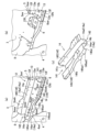
- FIG. 2 is a diagram showing a cross member according to an embodiment of the present invention.
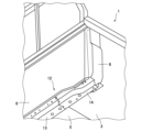
- FIG. 13 is a diagram showing reinforcements provided on the loading platform.
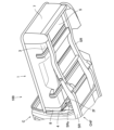
- FIG. 1 is a diagram showing a configuration of a loading platform in a conventional vehicle.
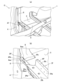
- FIG. 1 is an enlarged view of an end portion (left side in the vehicle width direction) of a cross member of a conventional vehicle loading platform.
- FIG. 1 shows a pickup truck type vehicle 1 having a ladder frame chassis.
- the bed 1 is placed on the upper surface of the portion of both side rails SR that extends rearward from the cabin C.
- multiple cross members made of a single member are installed in the vehicle width direction along the underside of the bed bottom.
- the foremost cross member 2f which is installed on the bed 1 closer to the cabin C, is placed on the side rail SR of the chassis frame CHF via a mountain-shaped support member SRs connected to the rail SR, and is fixed to this support member SRs by a bolt.
- This foremost cross member 2f of the bed and the cross member (not shown) at the rearmost part of the bed are most susceptible to the impact force transmitted from the side rail SR when the vehicle is traveling.
- the impact force generated by the unevenness of the road surface pushing up the vehicle is transmitted through the side rail SR, which can cause deformation of the cross members, particularly at both ends, and peeling around the welded areas.
- the cross member 2f at the front of the loading platform is a long steel material with a substantially hat-shaped cross section, and includes left and right wall portions 2fw and a bottom portion 2fb that form an opening on the upper side, i.e., an opening with a U-shaped cross section.
- the wall portion that faces the cabin C side when the cross member is extended in the vehicle width direction along the lower surface of the bottom of the loading platform is referred to as the right wall portion (in the case of the conventional cross member 2f, the right wall portion 2fwr).
- the cross member 2f includes left and right flanges 2ff that extend horizontally outward from the upper ends of the walls, and a folded portion 2ffe that is formed by folding the end of the flange 2ff, in this case, on the cabin C side, downward.
- the cross member may be deformed by twisting or the like around the L-shaped folded portion 2fo that connects the upper end of the wall portion 2fw and the flange 2ff, for example, at the left end of the cross member.
- the cargo bed 1 is provided with a side panel inner 3 and a side panel outer (not shown) that form the side walls of the cargo bed, and the side panel outer is provided as an exterior panel on the outer wall surface side of the side panel inner 3 that faces the outside of the cargo bed.
- the side panel outer is not shown.
- the cargo bed 1 is provided with a strut outer 4 that extends in the vertical direction, and the side panel inner 3 and the side panel outer are connected by this strut outer.
- this strut outer 4 facing the opposite side of the cabin C, a portion that is slightly lower than the center in the vertical direction is joined by spot welding to the surface of the folded portion 2ffe provided on the above-mentioned cross member 2f that faces the cabin C.
- the tip portions of the left and right ends of the cross member 2f are cut down diagonally toward the opposite side of the cabin C, i.e., toward the rear side of the cargo bed 1, in order to ensure an access path for the welding gun during welding.
- the total length of the left and right wall sections 2fw of the cross member 2f that is farther from the cabin C is shorter than the total length of the wall section that is closer to the cabin C.
- the side panel inners 3 are provided on the left and right sides of the loading platform 1 to form the side walls of the loading platform, and the lower portions of these side panel inners also form the ends of the loading platform floor in the vehicle width direction.
- the portions of the loading platform floor below the left and right side panel inners 3 are provided with floor panels 5 that are connected to these side panel inners and form the central portion of the bottom of the loading platform in the vehicle width direction.
- the left and right side panel inners 3 and the floor panel 5 connected to them form a storage area for loading luggage.
- the storage area is formed by the left and right side panel inners 3, the floor panel 5, a header board 6 (with cabin guard) erected at the front of the loading platform 1 facing the cabin C, and a tailgate 7 provided at the rear of the loading platform 1 in a foldable manner.
- the upper surface of the flange 2ff of the cross member 2f on the cabin C side is joined, for example at the left end of the cross member, to the underside of the lower part of the side panel inner 3 that constitutes the cargo bed floor by spot welding via a reinforcing material, reinforcement 8.
- Fig. 1 is a diagram showing an example of an embodiment in which a cross member according to the present invention is provided in a conventional vehicle bed.
- the cross member 12 of this embodiment is provided as the frontmost cross member of the bed 1 near the cabin C, and extends in the vehicle width direction along the underside of the bed bottom, as in the conventional case.
- the cross member 12 is divided into a first portion 13 that constitutes the center of the cross member and a second portion 14 that constitutes both sides of the cross member. In the figure, only the left side of the second portion 14 is shown.
- the second portion 14 of the cross member 12 has a thicker steel plate to increase its rigidity than the first portion 13.
- the cross member 12 of this embodiment is also placed on the side rail SR of the chassis frame CHF via a mountain-shaped support member SRs connected to the rail SR, as in the conventional vehicle, and is fixed to the support member SRs with a bolt. This bolt fixation is performed through a connection hole provided in the second portion 14 of the cross member 12.
- the cross member 12 of this embodiment is divided into the first portion 13 and the second portion 14, and the thickness of the steel plate of the second portion 14 attached to the chassis frame CHF is made thicker than that of the first portion 13. Therefore, in the cross member 12 of this embodiment, the weight of the cross member is not increased, and as described above, the rigidity of the second portion 14, where the impact force transmitted from the side rail SR is concentrated when driving on rough roads, is increased to prevent deformation, etc.
- the first and second parts 13 and 14 of the cross member 12 have a substantially hat-shaped cross section.
- the first and second parts 13 and 14 have left and right wall parts (13w of the first part, 14w of the second part) and bottom parts (13b of the first part, 14b of the second part) that form the opening on the upper surface side, i.e., the U-shaped cross section of the hat-shaped cross section.
- the second part 14 of the cross member 12 is fixed to the support member SRs provided on the chassis frame CHF by a bolt through a connection hole 14a provided in the bottom part 14b of the second part 14.
- the first and second parts 13 and 14 have left and right flanges (13f of the first part, 14f of the second part) that extend horizontally outward from the upper ends of the walls. Furthermore, the first part 13 and the second part 14 have a folded portion (13fe of the first part, 14fe of the second part) formed by folding the end of the flange, in this case on the cabin C side, downward.
- the side disposed closer to the cabin C is referred to as the "right” side or the “front” side of the loading platform/vehicle, and the other side disposed farther from the cabin C is referred to as the "left" side or the “rear” side of the loading platform/vehicle.
- the right wall portion or front wall portion the left flange or rear flange, the end portion of the right flange or the front end of the front flange, the left and right walls or the front and rear walls, the left and right flanges or the front and rear flanges, etc. of the second portion 14.
- the center of the bottom of the cargo bed in the vehicle width direction is formed by the floor panel 5.
- both ends of the bottom of the cargo bed in the vehicle width direction are formed by the left and right side panel inners 3 connected to this floor panel 5.
- these side panel inners 3 also form the side walls of the cargo bed 1.
- the length of the first part 13 in the longitudinal direction, i.e., in the vehicle width direction, is slightly longer than that of the floor panel 5.
- both ends of the first part 13 in the longitudinal direction extend toward the side walls of the cargo bed beyond the floor panel 5 that forms the center of the bottom of the cargo bed in the vehicle width direction, and are positioned near the joints between the floor panel 5 and the side panel inners 3 connected to it.
- the upper surfaces of the left and right flanges 13f of both ends of the first portion 13 arranged in the vicinity of the joint between the side panel inner 3 and the floor panel 5 are joined by spot welding to the lower surface of the portion of the side panel inner 3 near the joint.
- the flanges 13ft of both ends of the first portion 13 are joined to the portion of the side panel inner 3 near the joint, for example, at a welding point 3sw at the left end of the first portion 13.
- the upper surfaces of the left and right flanges 13f of the first portion 13 of the cross member 12, excluding both ends, are joined to the lower surface of the floor panel 5 by spot welding.
- the flanges 13f of the first portion 13, excluding both ends, are joined to the floor panel 5, for example, at a welding point 5sw at the left end of the first portion 13.
- the loading platform 1 includes the header board 6 that constitutes the front wall of the loading platform.
- the first portion 13 of the cross member 12 has its folded portion 13fe on a surface facing the cabin C (i.e., the front (toward) the vehicle) joined by spot welding to the opposite side of the cabin C of the lower end of the header board 6, i.e., the surface facing the rear side of the loading platform 1.
- the folded portion 13fe of the first portion 13 and the lower end of the header board 6 are joined, for example, at a welding point 6sw at the left end of the first portion 13.
- the second portions 14 constituting both sides of the cross member 12 are significantly modified in shape, etc., compared to the end of a conventional cross member shown in Figure 5 (particularly Figure 5(b)).
- the second portions 14 constituting both sides of the cross member 12 of this embodiment will be described below.
- the second part 14 of the cross member 12 has an inner end 141 connected to the first part 13, and an outer end 142 arranged on the side wall of the loading platform so as to face outward in the vehicle width direction with the cross member 12 extended on the underside of the bottom of the loading platform.
- the flange 14f provided on the upper part of the second part 14 has a larger width on the plane side of the outer end 142 than in the past.
- the width between the left and right walls 14w (including the opening on the upper surface) of the second part 14 and the width of the bottom 14b are constant from the inner end 141 to the approximately center in the vehicle width direction toward the outer end 142, and are narrower from there to the outer end 142.
- the width in the short direction of the second portion 14 between the approximate center in the vehicle width direction and the outer end 142 is thus reduced to about half of that of the conventional one.
- the width of the second portion 14 in the vehicle front-rear direction i.e., the front-rear direction of the loading platform 1 is reduced in the portion located outside the attachment portion (connection hole 14a) to the chassis frame CHF in the vehicle width direction compared to the portion located inside the attachment portion in the vehicle width direction.
- the width between the left and right wall portions 14w is gradually reduced so that the right wall portion 14wr on the cabin C side of the outer end portion 142 facing outward in the vehicle width direction moves toward the opposing left wall portion 14wl near the aforementioned approximate center portion. Then, when the width between the left and right wall portions 14w is reduced to a predetermined size, the width between the left and right wall portions 14w from there to the outer end portion 142 is maintained at that size.
- the second portion 14 has an opening on its upper surface that is straight on the left wall 14wl side and bottleneck-shaped on the right wall 14wr side, and the bottom 14b has a flat surface of the same shape.
- the flange 14fr provided on the upper part of the right wall portion 14wr is also shaped accordingly.
- the distance from the lower end of the header board 6 to the outer end 142 side of the wall surface of the right wall portion 14wr facing the cabin C is increased.
- the lower end of the header board 6 on the front wall of the loading platform and the opposing wall surface of the right wall portion 14wr on the outer end 142 side of the cross member 12 are separated, forming a space between them. In this embodiment, this space ensures an access path for the welding gun that welds the cross member.
- the second portion 14 of the cross member 12 has a folded portion 14fe formed by bending the end of the flange 14fr provided on the upper part of the right wall portion 14wr, which is approximately parallel to the right wall portion, downward in the vertical direction.
- the second portion 14 has two extensions on the outer end 142 side of the folded portion 14fe that are further extended vertically downward.
- the first extension 14fe1 is formed near the lower end of the folded portion 14fe that faces the portion where the bottleneck-shaped narrowing of the right wall portion 14wr ends and the width between the left and right wall portions becomes narrower. This first extension is also called an auxiliary flange portion.
- the second extension 14fee2 is formed near the lower end of the folded portion 14fe where the outer end 142 of the second part 14 contacts the inner end of the strut outer 4 in the vehicle width direction when the cross member 12 is extended onto the underside of the bed bottom.
- the folded portion 14fe of the second portion 14 is bent from the vicinity of the second extension portion 14fe2 on the outer end 142 side to the tip 14fet of the end facing outward in the vehicle width direction, so that it is widened toward the outer surface of the folded portion 14fe.
- the bent portion is processed so that the surface of the folded portion side of the approximately L-shaped cross section formed by the flange 14fr at the top of the right wall and the folded portion 14fe bent downward in the vertical direction connected thereto has an arc shape that bulges outward.
- the radius of curvature R of the arc-shaped surface of the folded portion 14fe is gradually increased from the vicinity of the second extension portion 14fe2 to the vicinity of the tip 14fet of the end facing outward in the vehicle width direction, so that the arc-shaped surface of the folded portion is gradually widened outward.
- the radius of curvature R of the arc-shaped surface of the folded portion 14fe provided in the second portion 14 is gradually increased from the vicinity of the second expansion portion 14fe2 toward the tip side of the outer end 142.
- the radius of curvature R of the corner between the flange 14fr at the upper part of the right wall portion of the second portion 14 and the folded portion 14fe connected thereto is increased toward the outside in the vehicle width direction.
- the upper and lower parts of the strut outer 4 extending from the welded portion to the vehicle width end of the cross member may be significantly deflected in the front-rear direction of the vehicle due to the vibrations and shocks transmitted to the cross member when the vehicle is traveling on rough roads.
- the vehicle width end of the cross member may be deformed around the welded portion due to the load caused by the deflection applied to the welded portion to the strut outer 4.
- the radius of curvature R of the arc-shaped surface in contact with the strut outer 4 at the second portion 14 gradually increases from near the second expansion portion 14fee2 toward the tip side of the outer end 142.
- the second part 14 having the above structure is disposed near the bottom end of the header board 6 that constitutes the front wall of the loading platform 1, and the connection part 141c on the inner end 141 side of the second part 14 is connected to the tip of the first part 13 of the cross member 12 attached to the underside of the loading platform 1 in such a way that it covers the tip of the first part 13.
- the connection between the second part 14 and the first part 13 is made in the vicinity of the joint between the side panel inner 3 and the floor panel 5 as described above, and the connection part 141c provided on the inner end 141 side of the second part 14 is made so as not to protrude from there to the floor panel 5 side.
- connection part 141c of the second part 14 and the flanges 13ft at both ends of the first part 13 and the joints of the side panel inner 3 described above is made, for example, at the left end of the cross member 12 at the welded point 3sw'.
- connection portion 141c of the second portion 14 facing the first portion 13 does not extend beyond the joint between the side panel inner 3 and the floor panel 5.
- the connection portion 141c provided on the inner end 141 of the second portion 14 is joined to the side panel inner 3 together with the end of the first portion 13 that is connected to it, so as to avoid the joint (joint) between the side panel inner and the floor panel. That is, in the cross member 12 of this embodiment, the first portion 13 is joined to the underside of the cargo bed of the side panel inner 3 and the floor panel 5.
- the second portion 14 is joined to the underside of the cargo bed of the side panel inner 3, but is not joined to the floor panel 5.
- the cross member 12 of this embodiment when vibrations or impacts are transmitted from the side rail SR when the vehicle is traveling on rough roads, etc., much of the load caused by the impact force, etc. is applied mainly to the second portion 14 of the cross member. In this case, the load is transmitted to the side panel inner 3 joined to the second portion 14 and dispersed by the side panel inner, so the first portion 13 of the cross member and the floor panel 5 joined thereto are unlikely to be directly affected by the load. Therefore, in the cross member 12 of this embodiment, it is possible to suppress the load generated by vibrations or impacts when traveling on rough roads, etc. from directly affecting the first portion 13 and the floor panel 5 joined thereto.
- the upper surface of the flange 14f provided on the upper part of the second portion 14 is joined to the underside of the lower part constituting the cargo floor of the side panel inner 3.
- the expanded upper surface of the flange 14fr provided on the upper part of the outer end 142 side of the right wall portion 14wr is joined in three layers to the underside of the lower part of the side panel inner 3 via a reinforcement 8.
- the upper surface portion of the upper surface of the flange 14fl provided on the upper part of the outer end 142 side of the left wall portion 14wl, close to the left wall portion, is also joined in three layers to the underside of the lower part of the side panel inner 3 via a reinforcement 8.
- the reinforcement 8 extends in the vertical direction of the cargo bed 1 and is a reinforcing material attached along the wall surface of the outer wall surface of the side panel inner 3 that constitutes the side wall of the cargo bed, facing the outside of the cargo bed, at the end closer to the cabin C.
- the lower end of the reinforcement 8 also extends in the vehicle width direction on the underside of the bottom of the cargo bed, which is also constituted by the side panel inner 3.
- the reinforcement 8 attached to the side panel inner 3 can suppress deformation due to shear force that may occur at the four corners of the cargo bed 1, particularly at the two front corners, due to vibrations and shocks caused when the vehicle is traveling on rough roads.
- the three-ply joining by spot welding via the reinforcement 8 is performed, for example, at the left end of the cross member 12, at the welding point 3swa.
- the other welding points, such as 3swb are joined in two layers by spot welding.
- the flange 14f on the outer end 142 side of the second portion 14 is joined to the underside of the lower portion of the side panel inner 3 via the reinforcement 8. Therefore, the impact force transmitted from the side rail SR to the second portion 14 of the cross member 12 when driving on rough roads, etc., is dispersed by the reinforcement 8, so that the transmitted impact force can be mitigated, particularly at the corners of the cargo bed where it is provided.
- the width of the plane of the flange 14f (particularly the right wall portion 14wr side) provided on the outer end portion 142 side of the second portion 14 is expanded more than in the past. Therefore, in the cross member 12 of this embodiment, when the impact force transmitted to the second portion 14 is transmitted to the reinforcement 8, the load can be distributed more effectively than in the conventional cross member with a narrow flange plane width.
- the width between the left and right wall portions 14w and the bottom portion 14b of the second portion 14 is gradually reduced and narrowed as it moves toward the outer end 142.
- the U-shaped cross section of the second portion 14 is tapered toward the outer end 142, thereby weakening the rigidity of the outer end 142 side of the second portion 14.
- the flange on the outer end 142 side of the second portion 14 is joined to the underside of the lower portion constituting the cargo floor of the side panel inner 3.
- the outer end side 142 of the second portion 14, which has reduced rigidity, can follow the deformation of the floor portion of the side panel inner 3, so that it is possible to prevent cracks and peeling from occurring around the joint between the flange and the side panel inner.
- the second portion 14 has a folded portion 14fe provided on the right wall portion 14wr side, and the surface of the folded portion 14fe facing the cabin C is joined at the connection portion 141c to a surface of the lower end of the header board 6 near the connection portion between the second portion 14 and the first portion 13, facing the rear side of the bed 1.
- This joining of the two sheets by spot welding is performed, for example, at the welding point 6swb.
- the second portion 14 has a surface of the folded portion 14fe facing the cabin C, the surface located near the first extension portion 14fe1 on the outer end 142 side, joined to a surface of the header board 6 lower end facing the rear side of the loading platform 1, closer to the strut outer 4.
- This two-sheet overlap joint by spot welding is performed, for example, at positions (joints) 6swc, 6swd, etc., overlapping in the vehicle width direction.
- the first extension portion (auxiliary flange portion) 14fe1 of the second portion 14 is formed by bending the lower end of the folded portion 14fe, which is located at a position where the joint between the folded portion 14fe and the header board 6 overlaps in the vehicle width direction, toward the front side of the vehicle (cabin C side).
- the cross member 12 of this embodiment can improve the rigidity of the folded portion 14fe, particularly in the portion where the joints overlap in the vehicle width direction.
- the impact force transmitted to the cross member 12 when the vehicle is traveling on rough roads, etc. is dispersed over an area enlarged by the auxiliary flange portion 14fe1 of the folded-back portion 14fe, thereby making it possible to reduce the load due to the impact force applied to those joints.
- the first extension portion 14fee1 has an inclined surface that slopes from the base of the portion extending from the folded portion 14fee toward the cabin C (the front of the vehicle) toward the lower tip. This is a device to facilitate the installation of the wire harness around the first extension portion 14fee1 and to prevent unnecessary contact of the wire harness with the first extension portion while the vehicle is traveling. Taking into consideration the state of the installation of the wire harness in advance, this inclined surface may be inclined in the opposite direction, away from the cabin C, that is, toward the rear of the loading platform (the rear of the vehicle).
- the second part 14 has a surface facing the cabin C of the connection part 141c provided on the inner end 141 side of the folded part 14fe joined to the surface of the lower end of the header board 6 facing the first part 13 via the connection part with the connection part.
- This three-ply joining by spot welding is performed, for example, at welding point 6sw'.
- the second part 14 has a surface facing the cabin C near the second extension part 14fe2 provided on the outer end 142 side of the folded part 14fe joined to the opposing surface near the inner end of the strut outer 4 in the vehicle width direction and the surface of the lower end of the header board 6.
- This three-ply joining by spot welding is performed, for example, at welding point 4sw'.
- the above-mentioned portion of the folded portion 14fe provided in the second portion 14 is joined to the surface of the lower end of the header board 6, thereby improving the rigidity of the cross member 12, particularly around the second portion 14 that constitutes both side portions.
- the cross member of this embodiment makes it possible to suppress deformation of the cross member caused by vibrations and impacts transmitted from the side rails when the vehicle is traveling on rough roads, as well as cracks and peeling at the joints. Therefore, according to the cross member of this embodiment, it is possible to improve the impact resistance of the cross member that extends in the vehicle width direction along the underside of the bottom of the vehicle bed.
- the cross member 12 has been described as a cross member located at the front end of the cargo bed 1, but the cross member 12 in this embodiment may be a cross member located at the rear end of the cargo bed 1.
- the cross member 12 By arranging the cross member 12 as the front and/or rear cross member of the cargo bed 1, it becomes possible to suppress deformation of the cargo bed caused by loads applied to the cargo bed due to vibrations and shocks when the vehicle is traveling on rough roads, in particular loads that are applied in a rolling manner near the four corners of the cargo bed.
Landscapes
- Engineering & Computer Science (AREA)
- Chemical & Material Sciences (AREA)
- Combustion & Propulsion (AREA)
- Transportation (AREA)
- Mechanical Engineering (AREA)
- Body Structure For Vehicles (AREA)
Abstract
Description
このような車両の一例が、例えば、特許文献1に開示されている。この従来の車両では、前進走行中、車両に急制動がかかった場合に、前方への慣性力が荷台のフロアに作用し、車幅方向に荷台底部の下面に沿って延設されたクロスメンバの特に両端部に屈曲変形が生じる可能性がある、という課題を解決している。具体的には、この車両では、荷台フロアの骨組みを成す一対のサイドメンバの後端間に、最後部クロスメンバが架設される。この最後部クロスメンバは、他のクロスメンバよりも高剛性なものとされる。そして、この最後部クロスメンバと、その直前にあるクロスメンバとの間には、補強部材が設けられ、この補強部材により、両クロスメンバが、その直前のクロスメンバをシャシーフレームに固定する車幅方向のフロア中央の位置で車両の前後方向に結合される。
荷台最前部のクロスメンバ2fは、断面ほぼハット形の長尺の鋼材であり、その上面側の開口、即ちコ字形断面の開口を形成する左右の壁部2fw、および底部2fbを備えている。以降の説明では、クロスメンバの左右の壁部のうち、同クロスメンバが荷台底部の下面に沿って車幅方向に延設された状態でキャビンC側を向く壁部を右壁部(この従来のクロスメンバ2fの場合は、右壁部2fwr)と称する。さらに、同クロスメンバ2fは、それら壁部の上端からそれぞれ外側に向かって水平に延出した左右のフランジ2ffおよび、フランジ2ffの、この場合キャビンC側の端部を、下方側に折り曲げて形成された折返部2ffeを備えている。このクロスメンバ2fは、その下方のサイドレールSRから衝撃力が伝達されると、同クロスメンバの、例えば左側端部において、壁部2fw上端とフランジ2ffとを繋ぐL字形折曲部2foを中心とするその周辺にねじれ等による変形が生じる場合がある。
以下、本発明の実施形態として、この考案の構造を採用した本発明に係るクロスメンバを、上記従来の車両100の有する荷台1に適用した例を説明する。
図1は、従来の車両の荷台において本発明に係るクロスメンバを備えた実施形態の一例を示す図である。図1に示すように、本実施形態のクロスメンバ12は、荷台1での最前部のクロスメンバとしてキャビンC寄りに設けられており、従来と同様に、荷台底部の下面に沿って車幅方向に延設されている。
図2(a)、(b)に示すように、クロスメンバ12の第1部分13および第2部分14は、ほぼハット形の断面を有している。これら第1部分13および第2部分14は、その上面側の開口、即ちハット形断面のコ字形断面部分を形成する左右の壁部(第1部分の13w、第2部分の14w)、および底部(第1部分の13b、第2部分の14b)を備えている。なお、上記のクロスメンバ12の第2部分14とシャシーフレームCHFに設けられた支持部材SRsとのボルトによる固定は、第2部分14の底部14bに設けられた接続孔14aを通じて行われている。そして、これら第1部分13および第2部分14は、それらの壁部上端からそれぞれ外側に向かって水平に延出した左右のフランジ(第1部分の13f、第2部分の14f)を備えている。さらに、第1部分13および第2部分14は、同フランジの、この場合キャビンC側の端部を、下方側に折り曲げて形成された折返部(第1部分の13fe、第2部分の14fe)を備えている。
なお、本明細書では、第1部分13および第2部分14の左右の壁部のうち、キャビンCの近くに配される側を「右」側あるいは荷台/車両の「前(方)」側、もう一方のキャビンCから遠くに配される側を「左」側あるいは荷台/車両の「後(方)」側と称する。これは、第1部分13および第2部分14の左右のフランジについても同様とする。具体的にいうと、例えば、第2部分14の右壁部あるいは前壁部、左フランジあるいは後フランジ、右フランジの端部あるいは前フランジの前端、左右の壁部あるいは前後の壁部、左右のフランジあるいは前後のフランジ、などと称する。
また、荷台1は、既述のとおり、荷台の前壁を構成するヘッダーボード6を備えている。そして、クロスメンバ12の第1部分13は、その折返部13feのキャビンC側(つまり車両前(方)側)を向いた面が、スポット溶接によりヘッダーボード6下端部のキャビンCの反対側、即ち荷台1の後方側を向いた面に接合されている。この第1部分13の折返部13feと、ヘッダーボード6の下端部との接合は、例えば第1部分13の左側端部では、溶接個所6sw等で行われている。
図2(a)、(c)に示すように、クロスメンバ12の第2部分14は、第1部分13と接続される側の内端部141および、クロスメンバ12が荷台底部の下面に延設された状態で車幅方向の外側を向くように荷台の側壁側に配される外端部142を有している。また、第2部分14の上部に設けられたフランジ14fは、特に、その外端部142側の平面の幅が従来よりも大きく拡張されている。また、それと反対に、第2部分14の左右の壁部14w間(上面側の開口を含む)、および底部14bの幅は、内端部141から外端部142に向かってその車幅方向の略中央部までが一定の大きさとされ、そこから外端部142までがそれよりも狭くされている。
さらに、第2部分14は、その折返部14feのキャビンC側を向いた面のうち、外端部142側の第1拡張部14fee1付近に位置する面が、ヘッダーボード6下端部の荷台1の後方側を向いたストラットアウタ4寄りの面に接合されている。このスポット溶接による2枚重ね接合は、例えば溶接個所(接合部)6swc、6swd等の位置で車幅方向に重複して行われている。この場合、第2部分14の有する第1拡張部(補助フランジ部)14fee1は、その折返部14feとヘッダーボード6との接合部が車幅方向に重複して存在する位置にある折返部14feの下端部を車両前側(キャビンC側)に折り曲げることにより形成されている。このような補助フランジ部14fee1を設けることで、本実施形態のクロスメンバ12では、特に、車幅方向において接合部が重複して存在する部分の折返部14feの剛性を向上させることができる。そのため、車両の悪路走行時等にクロスメンバ12に伝達される衝撃力は、折返部14feの補助フランジ部14fee1によって拡大された領域に分散されるようになるので、それら接合部に加わる衝撃力による荷重を低減することができるようになる。
従って、本実施形態のクロスメンバによれば、車両の荷台底部の下面に沿って車幅方向に延設されるクロスメンバの耐衝撃性を向上させることが可能となる。
3 サイドパネルインナ
4 ストラットアウタ
5 フロアパネル
6 ヘッダーボード
8 リインフォース
12 クロスメンバ
13 第1部分
14 第2部分
14wr 右壁部/前壁部
14wl 左壁部/後壁部
14fr フランジ (右フランジ/前フランジ)
14fl フランジ (左フランジ/後フランジ)
141 内端部
141c 接続部
142 外端部
14fe 折返部
14fee1 第1拡張部 (補助フランジ部)
14fee2 第2拡張部
100 車両
3sw′ 溶接個所 (3枚重ね接合、第1部分と第2部分との接続部)
4sw′ 溶接個所 (3枚重ね接合、ストラットアウタ)
6sw′ 溶接個所 (3枚重ね接合、ヘッダーボード下端部)
SR サイドレール
CHF シャシーフレーム
C キャビン
Claims (10)
- 車両の荷台底部の下面に沿って車幅方向に延在して接合されるクロスメンバの構造であって、
前記クロスメンバは、該クロスメンバの車幅方向の中央部を構成する第1部分と、該クロスメンバの車幅方向の両側部を構成する第2部分とに分割して構成され、
前記第2部分は、前記荷台の下方に配された前記車両のシャシーフレームに取り付けられ、かつ前記第1部分よりもその厚みが厚くされている、
ことを特徴とする、クロスメンバの構造。 - 請求項1に記載のクロスメンバの構造であって、
前記第2部分は、前記シャシーフレームとの取付部よりも車幅方向外側に位置する部分が、前記取付部より車幅方向内側に位置する部分と比べて、車両前後方向の幅が小さい、
ことを特徴とする、クロスメンバの構造。 - 請求項1に記載のクロスメンバの構造であって、
前記荷台底部は、車幅方向の中央部を構成するフロアパネルと、このフロアパネルと接続されて車幅方向の両端部を構成するサイドパネルインナとから成り、
前記第1部分は、前記フロアパネルと前記サイドパネルインナとの接続部より車幅方向外側に延在して前記フロアパネルおよび前記サイドパネルインナに接合され、
前記第2部分は、前記サイドパネルインナに接合される、
ことを特徴とする、クロスメンバの構造。 - 請求項3に記載のクロスメンバの構造であって、
前記第2部分は、
前記荷台の車幅方向および上下方向に延在し、かつ前記サイドパネルインナによって構成される前記荷台の底部および側壁に沿って取り付けられたリインフォース、に接合される、
ことを特徴とする、クロスメンバの構造。 - 請求項1~4の何れか一項に記載のクロスメンバの構造であって、
前記第1部分および前記第2部分は、前記荷台における最前部もしくは最後部に配置される、
ことを特徴とする、クロスメンバの構造。 - 請求項5に記載のクロスメンバの構造であって、
前記第1部分および前記第2部分は、前記荷台における最前部に配置され、前記荷台の前壁を構成するヘッダーボードの前記荷台の後方側を向いた面に接合される、
ことを特徴とするクロスメンバの構造。 - 請求項6に記載のクロスメンバの構造であって、
前記第1部分および前記第2部分は、ハット形断面を有するとともに、前記ハット形断面のコ字形断面部分を形成する前壁部および後壁部の上端からそれぞれ車両前後方向に向かって水平に延出した前フランジ部および後フランジ部、並びに、前記前フランジ部の前端を下方側に折り曲げて形成された折返部を有し、
前記前フランジ部および前記後フランジ部は、前記フロアパネルの下面と、前記サイドパネルインナの前記荷台底部の下面との双方に接合され、
前記折返部は、前記ヘッダーボードの前記荷台の後方側を向いた面に接合される、
ことを特徴とする、クロスメンバの構造。 - 請求項7に記載のクロスメンバの構造であって、
前記第2部分は、前記折返部と前記ヘッダーボードとの接合部が車幅方向に重複して存在する位置にある前記折返部の下端部を車両前側または車両後側に折り曲げて形成された補助フランジ部をさらに有する、
ことを特徴とする、クロスメンバの構造。 - 請求項7に記載のクロスメンバの構造であって、
前記サイドパネルインナとともに前記荷台の側壁を構成するサイドパネルアウタと、
前記サイドパネルインナと前記サイドパネルアウタとを接続して前記荷台の上下方向に延在するストラットアウタと、
をさらに備え、
前記折返部は、前記ストラットアウタに接合される、
ことを特徴とする、クロスメンバの構造。 - 請求項9に記載のクロスメンバの構造であって、
前記第2部分は、前記折返部の車幅方向外端部側に位置する部分の車両前方側を向いた面が、前記ストラットアウタの前記荷台の後方側を向いた面に接合され、
前記前フランジ部と前記折返部との角部の曲率半径は、車幅方向外側に向かうほど大きい、
ことを特徴とする、クロスメンバの構造。
Priority Applications (2)
| Application Number | Priority Date | Filing Date | Title |
|---|---|---|---|
| PCT/JP2023/011880 WO2024201580A1 (ja) | 2023-03-24 | 2023-03-24 | 車両荷台のクロスメンバ構造 |
| JP2025509220A JPWO2024201580A1 (ja) | 2023-03-24 | 2023-03-24 |
Applications Claiming Priority (1)
| Application Number | Priority Date | Filing Date | Title |
|---|---|---|---|
| PCT/JP2023/011880 WO2024201580A1 (ja) | 2023-03-24 | 2023-03-24 | 車両荷台のクロスメンバ構造 |
Publications (1)
| Publication Number | Publication Date |
|---|---|
| WO2024201580A1 true WO2024201580A1 (ja) | 2024-10-03 |
Family
ID=92904049
Family Applications (1)
| Application Number | Title | Priority Date | Filing Date |
|---|---|---|---|
| PCT/JP2023/011880 Ceased WO2024201580A1 (ja) | 2023-03-24 | 2023-03-24 | 車両荷台のクロスメンバ構造 |
Country Status (2)
| Country | Link |
|---|---|
| JP (1) | JPWO2024201580A1 (ja) |
| WO (1) | WO2024201580A1 (ja) |
Citations (3)
| Publication number | Priority date | Publication date | Assignee | Title |
|---|---|---|---|---|
| JPH06144287A (ja) * | 1992-11-06 | 1994-05-24 | Mitsubishi Motors Corp | トラツクの車台フレーム |
| JPH11115823A (ja) * | 1997-10-09 | 1999-04-27 | Hino Motors Ltd | 荷台構造 |
| JP2013244777A (ja) * | 2012-05-24 | 2013-12-09 | Toyota Auto Body Co Ltd | 貨物車両のデッキ構造 |
-
2023
- 2023-03-24 JP JP2025509220A patent/JPWO2024201580A1/ja active Pending
- 2023-03-24 WO PCT/JP2023/011880 patent/WO2024201580A1/ja not_active Ceased
Patent Citations (3)
| Publication number | Priority date | Publication date | Assignee | Title |
|---|---|---|---|---|
| JPH06144287A (ja) * | 1992-11-06 | 1994-05-24 | Mitsubishi Motors Corp | トラツクの車台フレーム |
| JPH11115823A (ja) * | 1997-10-09 | 1999-04-27 | Hino Motors Ltd | 荷台構造 |
| JP2013244777A (ja) * | 2012-05-24 | 2013-12-09 | Toyota Auto Body Co Ltd | 貨物車両のデッキ構造 |
Also Published As
| Publication number | Publication date |
|---|---|
| JPWO2024201580A1 (ja) | 2024-10-03 |
Similar Documents
| Publication | Publication Date | Title |
|---|---|---|
| US6688676B1 (en) | Vehicle structure with load transmission elements | |
| EP0937631B1 (en) | Automobile body frame | |
| US7237829B2 (en) | Unitized vehicle rear body structure | |
| CN104648492B (zh) | 车身下部结构 | |
| KR101108451B1 (ko) | 차량 전방 구조 | |
| JP6252617B2 (ja) | 車両の側部車体構造 | |
| CN107031722A (zh) | 车身前部构造 | |
| JP6256518B2 (ja) | 車両の側部車体構造 | |
| US20120119544A1 (en) | Car body with reinforcing structure | |
| EP2412612B1 (en) | Side sill structure for automobile | |
| JP6964642B2 (ja) | 自動車のサイドシル構造 | |
| EP0908372B1 (en) | Construction of root portion of front side member | |
| JP3692845B2 (ja) | 自動車の車体前部構造 | |
| KR102854823B1 (ko) | 차체구조 | |
| WO2024201580A1 (ja) | 車両荷台のクロスメンバ構造 | |
| JP3321065B2 (ja) | 自動車の車体フレーム補強構造 | |
| JP2014040209A (ja) | 車両の車体下部構造 | |
| US20230311722A1 (en) | Vehicle structure with anchor unit | |
| JP3537669B2 (ja) | 自動車の車体下側部補強構造 | |
| US20230312020A1 (en) | Side sill structure | |
| CN114056433B (zh) | 车辆的下部车身结构 | |
| CN104627250B (zh) | 车辆的地板构造 | |
| JP4083078B2 (ja) | 自動車の車体前部構造 | |
| JPH11115821A (ja) | 車両の下部車体構造 | |
| JP2003011845A (ja) | 車体構造 |
Legal Events
| Date | Code | Title | Description |
|---|---|---|---|
| 121 | Ep: the epo has been informed by wipo that ep was designated in this application |
Ref document number: 23930221 Country of ref document: EP Kind code of ref document: A1 |
|
| WWE | Wipo information: entry into national phase |
Ref document number: 2025509220 Country of ref document: JP |
|
| WWE | Wipo information: entry into national phase |
Ref document number: 2501006232 Country of ref document: TH |
|
| NENP | Non-entry into the national phase |
Ref country code: DE |
|
| 122 | Ep: pct application non-entry in european phase |
Ref document number: 23930221 Country of ref document: EP Kind code of ref document: A1 |