WO2024201547A1 - 蒸着装置、表示装置の製造方法 - Google Patents
蒸着装置、表示装置の製造方法 Download PDFInfo
- Publication number
- WO2024201547A1 WO2024201547A1 PCT/JP2023/011687 JP2023011687W WO2024201547A1 WO 2024201547 A1 WO2024201547 A1 WO 2024201547A1 JP 2023011687 W JP2023011687 W JP 2023011687W WO 2024201547 A1 WO2024201547 A1 WO 2024201547A1
- Authority
- WO
- WIPO (PCT)
- Prior art keywords
- deposition
- lid
- top plate
- lid portion
- deposition material
- Prior art date
- Legal status (The legal status is an assumption and is not a legal conclusion. Google has not performed a legal analysis and makes no representation as to the accuracy of the status listed.)
- Ceased
Links
Images





Classifications
-
- C—CHEMISTRY; METALLURGY
- C23—COATING METALLIC MATERIAL; COATING MATERIAL WITH METALLIC MATERIAL; CHEMICAL SURFACE TREATMENT; DIFFUSION TREATMENT OF METALLIC MATERIAL; COATING BY VACUUM EVAPORATION, BY SPUTTERING, BY ION IMPLANTATION OR BY CHEMICAL VAPOUR DEPOSITION, IN GENERAL; INHIBITING CORROSION OF METALLIC MATERIAL OR INCRUSTATION IN GENERAL
- C23C—COATING METALLIC MATERIAL; COATING MATERIAL WITH METALLIC MATERIAL; SURFACE TREATMENT OF METALLIC MATERIAL BY DIFFUSION INTO THE SURFACE, BY CHEMICAL CONVERSION OR SUBSTITUTION; COATING BY VACUUM EVAPORATION, BY SPUTTERING, BY ION IMPLANTATION OR BY CHEMICAL VAPOUR DEPOSITION, IN GENERAL
- C23C14/00—Coating by vacuum evaporation, by sputtering or by ion implantation of the coating forming material
- C23C14/22—Coating by vacuum evaporation, by sputtering or by ion implantation of the coating forming material characterised by the process of coating
- C23C14/24—Vacuum evaporation
Definitions
- This disclosure relates to a deposition apparatus for forming a deposition film and a method for manufacturing a display device using the deposition apparatus.
- a known method for forming thin films is the vapor deposition method, in which a material in a crucible is melted and evaporated using a heater, and then brought into contact with the surface of an object positioned above the crucible and solidified to form a thin film containing the material on the surface of the object.
- a vapor deposition method using a vapor deposition device may be used to form each layer of the light-emitting element in order to reduce deterioration of the layers.
- Patent Document 1 discloses a maintenance method in which the lid is moved to a recovery mechanism and then heated to re-evaporate the deposition material and remove it from the lid.
- the deposition device includes a crucible having an opening for releasing deposition material toward a deposition target, and a lid that moves between a blocking position that prevents the deposition material from reaching the deposition target and an open position where the deposition material reaches the deposition target, and the lid includes a top plate that overlaps with the opening when the lid is in the blocking position as viewed from the position where the deposition target is placed, at least one hole that communicates with the top plate, and a cap that closes each of the holes in an openable and closable manner.
- the vapor deposition material adhering to the lid can be removed more easily, improving the maintainability of the lid.
- FIG. 1 is a schematic cross-sectional side view of a vapor deposition apparatus according to a first embodiment.
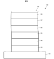
- 1 is a schematic side cross-sectional view of a display device according to each embodiment.
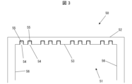
- FIG. 2 is a schematic cross-sectional side view of a lid according to the first embodiment.
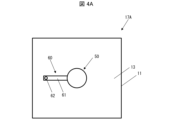
- 4 is a schematic plan view of the second space when the lid portion according to the first embodiment is in a blocking position.
- FIG. 4 is a schematic plan view of the second space when the lid portion according to the first embodiment is in an open position.
- FIG. 4 is a schematic cross-sectional side view of the crucible and the lid, illustrating how the lid according to the first embodiment is in a blocking position blocking the deposition material discharged from the crucible.
- FIG. 4 is a schematic cross-sectional side view of the lid portion showing how the inner lid of the lid portion according to the first embodiment is removed from the outer lid.
- FIG. 5 is a schematic cross-sectional side view of the inner lid of the lid portion according to the first embodiment, illustrating how the inner lid is cleaned.
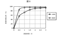
- FIG. 11 is a graph showing the relationship between the cleaning time of the lid portion and the removal rate of the deposition material in the cleaning steps according to each of an example and a comparative example.
- FIG. 11 is a schematic cross-sectional side view of a lid according to a second embodiment. 11 is a schematic cross-sectional side view of the crucible and the lid, illustrating how the lid according to the second embodiment is in a blocking position blocking the deposition material discharged from the crucible.
- FIG. 11 is a schematic cross-sectional side view of the inner lid of the lid portion according to the second embodiment, showing how the inner lid is cleaned.
- FIG. FIG. 11 is a schematic cross-sectional side view of a
- FIG. 2 is a schematic side cross-sectional view of a display device 100 according to this embodiment.
- the display device 100 is a device that can be used, for example, as a display for a television or a smartphone.
- the display device 100 includes a substrate 101, for example a TFT substrate, and a plurality of light-emitting elements 102 formed on the substrate 101.
- the light-emitting element 102 has, for example, from the substrate 101 side, anode 103 as a first electrode, hole injection layer 104, hole transport layer 105, light-emitting layer 106, electron transport layer 107, and cathode 108 as a second electrode.
- the structure of the light-emitting element 102 is not limited to the above configuration, and may have, from the substrate 101 side, cathode 108, electron transport layer 107, light-emitting layer 106, hole transport layer 105, hole injection layer 104, and anode 103.
- the light-emitting element 102 has at least the light-emitting layer 106 between the anode 103 and the cathode 108, it is not necessary to have at least one of the hole injection layer 104, hole transport layer 105, and electron transport layer 107.
- the light-emitting element 102 has a functional layer including at least the light-emitting layer 106 between the anode 103 and the cathode 108.
- the light-emitting element 102 may also have further functional layers, including, for example, an electron injection layer between the electron transport layer 107 and the cathode 108.
- the display device 100 applies a voltage between the anode 103 and the cathode 108 of each light-emitting element 102 via a driver (not shown) formed on the substrate 101.
- Each light-emitting element 102 to which a voltage is applied injects holes from the anode 103 into the light-emitting layer 106 via the hole injection layer 104 and the hole transport layer 105, and also injects electrons from the cathode 108 into the light-emitting layer 106 via the electron transport layer 107.
- the light-emitting layer 106 has a light-emitting material, for example an organic light-emitting material, and emits light due to excitons generated by recombination of the injected holes and electrons.
- At least one of the anode 103 and the cathode 108 is a transparent electrode that is light-transmitting, and the light-emitting element 102 extracts light generated from the light-emitting layer 106 to the side of the transparent electrode. In this way, the display device 100 displays by extracting light individually from each light-emitting element 102.
- the manufacturing method of the display device 100 according to this embodiment includes, for example, a method of sequentially depositing each layer of the light-emitting element 102 on the substrate 101.
- a method of sequentially depositing each layer of the light-emitting element 102 on the substrate 101 includes, for example, a method of sequentially depositing each layer of the light-emitting element 102 on the substrate 101.
- at least one of the layers of the light-emitting element 102 is deposited by a deposition method using a deposition apparatus described below.
- Fig. 1 is a schematic side cross-sectional view of the deposition apparatus 1 according to the present embodiment.
- Fig. 1 also illustrates a deposition target X (described later) on whose surface a deposition film is formed by the deposition apparatus 1, and a deposition material M (described later) that is a material for the deposition film and is stored inside a crucible body 41 (described later).
- the deposition apparatus 1 includes a vacuum chamber 10, a holding unit 20, a shutter 30, a crucible 40, a lid unit 50, and a lid holding unit 60.
- the deposition device 1 includes a crucible 40 and a lid 50.
- the crucible 40 has an opening 42 that releases the deposition material M toward the deposition target X.
- the lid 50 moves between a blocking position that prevents the deposition material M from reaching the deposition target X and an open position where the deposition material M reaches the deposition target.
- the lid 50 also includes a top plate 53, at least one hole 54, and at least one cap 55.
- the top plate 53 is located at a position that overlaps with the opening 42 when viewed from the position where the deposition target X is placed.
- the hole 54 communicates with the top plate 53, and the cap 55 closes the hole 54 so that it can be opened and closed.
- the vacuum chamber 10 includes a housing 11 , a first partition 12 , a second partition 13 , a first partition opening 14 , and a second partition opening 15 .
- the housing 11 is hollow, and the first partition 12 and the second partition 13 extend approximately parallel to the upper bottom surface of the housing 11 inside the housing 11, dividing the inside of the housing 11 into a plurality of spaces. Therefore, the inside of the housing 11 is divided into a first space 16 above the first partition 12, a second space 17 between the first partition 12 and the second partition 13, and a third space 18 below the second partition 13.
- a first partition opening 14 is formed in the first partition 12, and the first space 16 partitioned by the first partition 12 communicates with the second space 17 via the first partition opening 14.
- a second partition opening 15 is formed in the second partition 13.
- An opening 42 of a crucible 40, which will be described later, is inserted into the second partition opening 15 and sealed. Therefore, the second space 17 does not communicate with the third space 18.
- the housing 11 may have an entrance communicating with the first space 16, and a door section that seals the entrance so that it can be opened and closed.
- the deposition target X may be placed inside the vacuum chamber 10 through the entrance of the housing 11.
- the deposition target X is held in the first space 16 by the holding section 20 described below, and the entrance is sealed by the door section, and at least the first space 16 and the second space 17 inside the housing 11 can be evacuated by a pump (not shown).
- the shape of the housing 11 may be cylindrical from the viewpoint of maintaining strength when the first space 16 and the second space 17 are evacuated, but is not limited to this and may be rectangular.
- the holder 20 has an arm 21 formed in the first space 16.
- the arm 21 is formed on the upper inner surface of the housing 11.
- the holder 20 holds the deposition target X in the first space 16 by placing the deposition target X on the arm 21 facing toward the side.
- ⁇ Deposition equipment shutter>
- the shutter 30 is moved by a drive unit (not shown) between a blocking position where it overlaps with the first partition opening 14 and an open position where it does not overlap with the first partition opening 14 when viewing the first partition opening 14 from the deposition target X held by the holding unit 20.
- the deposition target X held by the holding unit 20 faces the second space 17 via the first partition opening 14. Note that in this specification, a case where the shutter 30 is in the open position will be described unless otherwise specified.
- the crucible 40 includes a crucible body 41, which is a hollow container, and an opening 42, for example, of a cylindrical shape, which communicates with the inside and outside of the crucible body 41.
- the inside of the crucible body 41 contains, for example, a sublimable deposition material M that is solid at room temperature.
- the crucible body 41 is located inside the third space 18, and as described above, the opening 42 is inserted into the second partition opening 15 to seal the second partition opening 15. As a result, the inside of the crucible body 41 and the second space 17 communicate with each other through the opening 42.
- the crucible 40 heats the inside of the crucible body 41 with a heater (not shown), thereby heating and sublimating the deposition material M stored inside the crucible body 41.
- the opening 42 discharges the deposition material M sublimated inside the crucible body 41 toward the second space 17, in other words, toward the deposition target X.
- the shape of the crucible body 41 may be a cylindrical shape, a rectangular shape, or the like, and is not particularly limited.
- the material of each part of the crucible 40 includes, for example, titanium, but is not particularly limited.
- Fig. 3 is a schematic cross-sectional view of the lid portion 50, and is a schematic enlarged view of the vicinity of the lid portion 50 in the cross-section shown in Fig. 1.
- the schematic cross-sectional side views including Fig. 3 show cross-sections corresponding to the cross-section shown in Fig. 1.
- the lid portion 50 includes an inner lid 51 and an outer lid 52.
- the inner lid 51 has a top plate portion 53, a plurality of holes 54, a plurality of caps 55, and a side portion 56 facing the top plate portion 53.
- the top plate portion 53 is a plate-like member having, for example, a disk shape. Each of the holes 54 communicates with the top plate portion 53.
- the caps 55 are formed in the same number as the number of holes 54, and close each of the holes 54 in an openable and closable manner.
- the lid portion 50 according to this embodiment includes a plurality of holes 54 and a plurality of caps 55, and each of the caps 55 closes each of the holes 54 in an openable and closable manner.
- the caps 55 may be rotatably restrained to the top plate portion 53, for example.
- Figures 1 and 3 illustrate a state in which all of the caps 55 close the corresponding holes 54.
- the outer lid 52 supports the inner lid 51 in a removable manner using a support mechanism (not shown).
- the outer lid 52 supports the inner lid 51 so as to cover the outside of the top plate portion 53 and side portions 56.
- each part of the lid portion 50 is not particularly limited. However, as described below, in order to reduce deformation of the lid portion 50 in cases where sublimated vapor deposition material M adheres to each part of the lid portion 50, the material of each part of the lid portion 50 may be a low-expansion metal material, including SUS.
- the lid holding portion 60 includes, for example, a beam 61 and a beam shaft 62.
- the beam 61 has, for example, a straight rod shape, and the outer lid 52 is attached to one end.
- the beam shaft 62 is, for example, fixed to the upper surface of the second partition wall 13, and restrains the other end of the beam 61 on the side opposite to the side to which the outer lid 52 is attached. In particular, the beam shaft 62 restrains the beam 61 so that it can rotate around an axis in the vertical direction.
- the deposition device 1 to control the position of the lid portion 50 by controlling the rotation of the beam 61 around the beam shaft 62.
- the beam 61 may be integral with the outer lid 52. Also, the beam 61 may be removable from the beam shaft 62 together with the lid portion 50.
- Figs. 4A and 4B are both schematic plan views of the second space 17 as viewed from a position where the deposition target X is held toward the crucible 40, that is, the direction T1 shown in Fig. 1.
- Fig. 4A shows a schematic plan view of the second space 17A when the lid portion 50 is in the blocking position
- Fig. 4B shows a schematic plan view of the second space 17B when the lid portion 50 is in the open position.
- the lid portion 50 When the lid portion 50 is in the blocking position, as shown in FIG. 4A, when the opening 42 of the crucible 40 is viewed from the position where the deposition target X is placed, in other words, when the opening 42 is viewed in direction T1, the lid portion 50 is in a position that hides the opening 42. In particular, when the lid portion 50 is in the blocking position, when the opening 42 is viewed in direction T1, the top plate portion 53 overlaps with the opening 42. Furthermore, when the lid portion 50 is in the blocking position, the outer lid 52 supports the inner lid 51 on the side opposite the opening 42 relative to the inner lid 51, in other words, on the side of the deposition target X.
- the blocking position of the lid portion 50 is the position where the lid portion 50 prevents the deposition material M from reaching the deposition target X.
- the lid portion 50 when the lid portion 50 is in the blocking position, the beam 61 rotates around the beam shaft 62, and the lid portion 50 moves from the blocking position to the open position shown in FIG. 4B.
- the lid portion 50 when the lid portion 50 is in the open position, as shown in FIG. 4B, when the opening 42 is viewed in the direction T1, the lid portion 50 is positioned around the opening 42. Therefore, when the lid portion 50 is in the open position, the lid portion 50 is not present on the path that the deposition material M released from the opening 42 takes to reach the deposition target X. Therefore, the open position of the lid portion 50 is the position where the deposition material M released from the opening 42 reaches the deposition target X.
- the deposition apparatus 1 includes a single crucible 40, the present invention is not limited to this.
- the deposition apparatus 1 may include a plurality of crucibles 40 each having a different deposition material M contained therein, which is stored in the crucible body 41.
- the deposition apparatus 1 may include a lid portion 50 and a lid holding portion 60 for each of the crucibles 40.
- the deposition target X may be introduced into the deposition device 1 using a transport device (not shown) including, for example, a conveyor.
- the transport device may be configured to transport the deposition target X inside the vacuum chamber 10 while facing the surface of the deposition target X on which the deposition film is formed toward the crucible 40.
- the transport device may also function as the holding unit 20 that holds the deposition material X inside the vacuum chamber 10.
- the deposition apparatus 1 may include a control unit (not shown) that controls the operation of each unit.
- the control unit may control, for example, the evacuation of the inside of the vacuum chamber 10, the movement of the shutter 30, the heating of the crucible 40, and the movement of the lid unit 50.
- the manufacturing method of the display device 100 according to this embodiment includes the steps of sequentially forming the layers of the light emitting element 102 on the substrate 101, and at least one of the layers of the light emitting element 102 is formed using the deposition apparatus 1.
- the functional layers of the light-emitting element 102 including the hole injection layer 104, the hole transport layer 105, the light-emitting layer 106, and the electron transport layer 107, contain an organic material
- the functional layers may be formed by a deposition method in order to reduce deterioration of the functional layers.
- the new layer when a new layer is formed on the layer containing the organic material after it has been deposited, the new layer may be formed by a deposition method in order to reduce deterioration of the layer that has already been formed.
- any layer of the light-emitting element 102 using the deposition apparatus 1 for example, a laminate including the substrate 101, in which the layers on the substrate 101 side of the layer to be formed are formed, is placed inside the vacuum chamber 10 as the deposition target X.
- the laminate is placed on the arm 21 with the surface on which the deposition film is to be formed facing downward, in other words, toward the crucible 40.
- the deposition apparatus 1 evacuates the first space 16 and the second space 17 of the vacuum chamber 10, creating a vacuum in the first space 16 and the second space 17.
- the deposition device 1 heats the crucible 40, in which the material of the layer to be formed is stored inside the crucible body 41 as the deposition material M, and sublimes the deposition material M.
- the deposition material M sublimated inside the crucible 40 is released from the opening 42 of the crucible 40 toward the laminate, which is the deposition target X.
- the deposition material M discharged from the opening 42 reaches the surface of the laminate.
- the deposition material M that reaches the surface of the laminate is cooled by contact with the surface of the laminate and becomes solid again. As a result, a deposition film containing the deposition material M is formed on the surface of the laminate facing the crucible 40.
- the layers of the light-emitting element 102 for example at least one of the anode 103 and the cathode 108, and the light-emitting layer 106 may be formed in an island shape for each subpixel on the substrate 101.
- deposition of each layer may be performed through a deposition mask, such as a metal mask, that is placed on the side of the crucible 40 of the laminate and has openings at positions corresponding to each subpixel.
- a layer containing multiple materials may be formed by co-deposition in which multiple crucibles 40 are heated simultaneously to form a film.
- At least one of the layers of the light-emitting element 102 may be formed by a vapor deposition method using the vapor deposition apparatus 1.
- some of the layers of the light-emitting element 102 may be formed by a method other than the vapor deposition method, such as a sputtering method, a photolithography method, or an inkjet method.
- the sublimated deposition material M starts to be released from the opening 42 when the crucible 40 is heated to a degree necessary for sublimating the deposition material M.
- the deposition rate of the deposition film formed on the deposition target X may be unstable until the crucible 40 is sufficiently heated.
- the deposition rate refers to, for example, the film thickness of the deposition film formed on the deposition target X per unit time, and corresponds to the deposition speed of the deposition film on the deposition target X.
- the deposition device 1 moves the lid portion 50 to a blocking position to prevent the sublimated deposition material M from reaching the deposition target X.
- the deposition device 1 moves the lid portion 50 from the blocking position to an open position to allow the sublimated deposition material M to reach the deposition target X. This allows the deposition device 1 to perform deposition of the deposition film to be formed on the deposition target X while stabilizing the deposition rate.
- FIG. 5 is a schematic cross-sectional side view of the crucible 40 and the lid portion 50, illustrating the state in which the lid portion 50 in the blocking position blocks the vapor deposition material M discharged from the crucible 40.
- FIG. 5 omits the illustration of each part of the vapor deposition device 1 other than the crucible 40 and the lid portion 50.
- the sublimated deposition material M is released from the opening 42 in the direction T2, which is the direction from the opening 42 toward the deposition target X.
- the lid portion 50 when the lid portion 50 is in the blocking position, the lid portion 50, particularly the top plate portion 53 of the lid portion 50, is located in the direction from the opening 42 toward the direction T2. Therefore, when the deposition material M is released from the opening 42 while the lid portion 50 is in the blocking position, the released deposition material M comes into contact with the top plate portion 53, where it is cooled and returns to a solid.
- the deposition material M that is prevented from reaching the deposition target X by the lid portion 50 is fixed to the lid portion 50, particularly to the underside of the top plate portion 53.
- the caps 55 close each hole 54. Therefore, even if the deposition material M released from the crucible 40 reaches a certain hole 54, the deposition material M comes into contact with the underside of the cap 55 that closes that hole 54. Therefore, the inner lid 51 reduces adhesion of the deposition material M to the outer lid 52.
- the deposition apparatus 1 may use the shutter 30 in the blocking position to prevent the deposition material M from reaching the deposition target X.
- the deposition apparatus 1 may mainly use the lid portion 50, which is closer to the crucible 40 than the shutter 30, to prevent the deposition material M from reaching the deposition target X.
- Figure 6 is a schematic cross-sectional view of the lid portion 50 showing how the inner lid 51 is removed from the outer lid 52.
- Figure 7 is a schematic cross-sectional view of the inner lid 51 showing how the inner lid 51 is cleaned by removing the deposition material M from the inner lid 51.
- the lid portion 50 may be removed to the outside of the vacuum chamber 10.
- the beam 61 integral with the outer lid 52 may be removed from the beam shaft 62.
- the inner lid 51 may be removed from the outer lid 52.
- another inner lid 51 from which the deposition material M has been removed in advance may be attached to the outer lid 52, and may be placed again inside the vacuum chamber 10. This allows the deposition process to be performed using the deposition device 1 even while the inner lid 51 is being cleaned.
- the hole 54 is opened, for example, by rotating the cap 55 relative to the top plate portion 53.
- This allows air introduced through the hole 54 to flow between the top plate portion 53 and the deposition material M fixed to the top plate portion 53. Therefore, by operating the cap 55 to open the hole 54, the vacuum between the top plate portion 53 and the deposition material M is broken, and as shown in FIG. 7, the deposition material M detaches from the top plate portion 53 due to its own weight. Air may be introduced into the hole 54 from the side opposite to the surface of the top plate portion 53 to which the deposition material M is attached. In this case, the deposition material M can be more thoroughly removed from the top plate portion 53.
- the deposition material M can be removed from the top plate portion 53.
- the holes 54 are closed by manipulating the caps 55 of the cleaned inner lid 51.
- the inner lid 51 is attached to the outer lid 52, and the lid portion 50 including the inner lid 51 and the outer lid 52 is attached to the inside of the vacuum chamber 10. This completes the cleaning process of the lid portion 50.
- the deposition device 1 includes a lid portion 50 capable of blocking the deposition material M released from the crucible 40 from reaching the deposition target X.
- the lid portion 50 includes a top plate portion 53 with which the deposition material M comes into contact and adheres in a process of blocking the deposition material M, a hole 54 communicating with the top plate portion 53, and a cap 55 that closes and opens/closes the hole 54. For this reason, as described above, even if the deposition material M is adhered to the top plate portion 53 of the lid portion 50, it is possible to remove a large amount of the deposition material M adhered to the top plate portion 53 at once by operating the cap 55 to open the hole 54.
- Another method for removing deposition material from an object such as a lid to which it has been adhered is to scrape the deposition material directly off the object with a long object such as a metal spoon.
- This cleaning method requires the deposition material to be removed from the object in small amounts with the long object, and tends to take a long time to clean.
- the vapor deposition material comes into contact with the long member, and as a result, the recovered vapor deposition material may become contaminated with materials such as metals contained in the long member, making it difficult to reuse the vapor deposition material. Furthermore, when the vapor deposition material is directly scraped off an object with the long member, the long member may also come into contact with the object, which may cause problems such as scratches on the object's surface and contamination of the scratches with materials such as metals contained in the long member.
- the deposition device 1 according to this embodiment can remove a large amount of deposition material M from the lid portion 50 at once by the cleaning process described above, so that the deposition material M adhering to the lid portion 50 can be removed easily and in a short time, improving maintainability.
- the cleaning process of the lid portion 50 can be performed simply by operating the cap 55, and there is no need to bring other members into contact with the lid portion 50 or the deposition material M. Therefore, the deposition device 1 according to this embodiment reduces the inclusion of foreign matter in the deposition material M removed by the cleaning process of the lid portion 50, facilitates the reuse of the deposition material M, and reduces contamination of the lid portion 50.
- another method for removing the deposition material M that has adhered to the inside of the inner lid 51 of the lid portion 50 is to form a hole in the side portion 56 that penetrates the side portion 56 and introduce air through the hole.
- air is introduced through the hole in the side portion 56, the vacuum between the deposition material M and the top plate portion 53 will be maintained, and there is a possibility that the deposition material M will remain adhered to the top plate portion 53.
- the method of cleaning the lid portion 50 according to this embodiment breaks the vacuum between the deposition material M and the top plate portion 53, making it easier for the deposition material M to separate from the top plate portion 53. Therefore, the deposition device 1 according to this embodiment is provided with a lid portion 50 having a hole 54 in the top plate portion 53, thereby improving the maintainability of the lid portion 50 compared to a case in which the deposition device 1 is provided with a lid portion having a through hole in the side portion 56.
- the manufacturing method of the display device 100 improves costs and tact time because any of the layers of the light-emitting element 102 is formed using a vapor deposition apparatus 1 with improved maintainability.
- the vapor deposition apparatus 1 used in the manufacturing method of the display device 100 reduces contamination of the lid portion 50, so the manufacturing method reduces the intrusion of foreign matter into the light-emitting element 102 and improves the quality of the light-emitting element 102.
- the lid part 50 according to the present embodiment includes an inner lid 51 having a top plate part 53 to which the deposition material M is fixed, and an outer lid 52 that detachably supports the inner lid 51. Therefore, the deposition device 1 according to the present embodiment can perform a deposition process using the lid part 50 in which another inner lid 51 is attached to the outer lid 52, even during a cleaning process of the inner lid 51.
- the lid portion 50 includes a plurality of holes 54 and a plurality of caps 55, and each of the caps 55 closes each of the holes 54 in an openable and closable manner. Therefore, by simultaneously opening the multiple holes 54 during the cleaning process of the lid portion 50, the deposition material M can be more reliably removed from the top plate portion 53, and the deposition device 1 can reduce the amount of deposition material M remaining on the lid portion 50 during the cleaning process.
- the lid portion 50 only needs to include at least one hole 54 and at least one cap 55 that closes the hole 54 in an openable and closable manner.
- the vapor deposition device according to the example has the same configuration as the vapor deposition device 1 according to the present embodiment, including the lid portion 50.
- the vapor deposition device according to the comparative example has only an inner lid 51 as the lid portion 50, and does not have an outer lid 52. Furthermore, the inner lid 51 according to the comparative example does not include a hole 54 and a cap 55. Except for the above points, the vapor deposition device according to the comparative example has the same configuration as the vapor deposition device 1 according to the present embodiment.
- deposition of a deposition film using each deposition device was performed until the cleaning process for each lid portion 50 was required, and then the cleaning process for the lid portion 50 was performed.
- the inner lid 51 was removed from the outer lid 52
- the hole 54 was opened by operating the cap 55
- the deposition material M was removed from the top plate portion 53.
- the entire lid portion 50 was removed from the deposition device, and the deposition material M adhering to the top plate portion 53 was removed from the top plate portion 53 by scraping it off with a metal spoon.
- the weight of the inner lid 51 or the lid portion 50 having the top plate portion 53 to which the vapor deposition material M was adhered was measured prior to the cleaning process.
- the weight adhered to the top plate portion 53 was calculated in each of the examples and comparative examples.
- the weight of the vapor deposition material M removed from the top plate portion 53 was measured while measuring the elapsed time from the start of the cleaning process.
- the ratio of the weight of the vapor deposition material M removed from the top plate portion 53 to the weight of the vapor deposition material M adhered to the top plate portion 53 for each elapsed time from the start of the cleaning process was calculated in each of the cleaning processes of the examples and comparative examples.
- Figure 8 is a graph showing the relationship between the cleaning time and the removal rate of the deposition material.
- the horizontal axis shows the cleaning time, in other words the time (unit: hour) for which the cleaning process is performed
- the vertical axis shows the removal rate of the deposition material, in other words the ratio, expressed as a percentage, of the weight of the deposition material M removed from the top plate portion 53 to the total weight of the deposition material M adhered to the top plate portion 53.
- the measured values in the examples are plotted as circles and the measured values in the comparative examples are plotted as squares, and an interpolation line is also shown between the plots of the examples and the comparative examples.
- the deposition device according to the embodiment can remove more deposition material M from the lid portion 50 in a shorter time, improving maintainability.
- the vapor deposition material M removed in the cleaning process of the embodiment is prevented from coming into contact with other components, there is a low possibility that foreign matter has been mixed in, and the removed vapor deposition material M can be easily reused.
- the metal material of the spoon has been mixed in with the vapor deposition material M removed in the cleaning process of the comparative example, making it difficult to reuse the removed vapor deposition material M.
- the inner lid 51 is removed from the outer lid 52 and the inner lid is simply cleaned.
- deposition of a deposition film using the deposition device can be performed during the cleaning process.
- the lid portion 50 is removed from the deposition device, so deposition of a deposition film using the deposition device is difficult during the cleaning process.
- the deposition device according to the embodiment has improved maintainability, makes it easier to reuse the deposition material, reduces the inclusion of foreign matter in the deposition film, and makes it easier to simultaneously carry out the cleaning process and the deposition process.
- the vapor deposition device 1 according to this embodiment is different in configuration from the vapor deposition device 1 according to the previous embodiment only in that the vapor deposition device 1 includes a lid portion 70 instead of the lid portion 50.
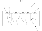
- FIG. 9 is a schematic cross-sectional side view of the lid portion 70 according to this embodiment.
- the lid portion 70 according to this embodiment differs from the lid portion 50 according to the previous embodiment only in that it includes an inner lid 71 instead of the inner lid 51.
- the inner lid 71 according to this embodiment differs from the inner lid 51 according to the previous embodiment only in that it further includes a partition wall 72 formed on the top plate portion 53.
- the outer lid 52 detachably supports the inner lid 71.
- the partition wall 72 protrudes from the top plate portion 53 in approximately the same direction as the side portion 56 protrudes from the top plate portion 53. In other words, when the lid portion 70 is in the blocking position, it protrudes from the surface of the top plate portion 53 on the side of the opening portion 42. Furthermore, when the lid portion 70 is in the blocking position, the partition wall 72 divides the space on the side of the opening portion 42 into multiple spaces.
- the lid portion 70 is partitioned by the partitions 72 into a plurality of regions including a plurality of first regions 73 and a plurality of second regions 74.
- each region of the lid portion 70 partitioned by the partitions 72 refers to a region including the partitions 72 or the side portions 56, and the top plate portion 53 surrounded by these.
- the area of the top plate portion 53 in each first region 73 is larger than the area of the top plate portion 53 in each second region 74.
- the lid portion 70 has at least one hole 54 in each of the multiple regions partitioned by the partitions 72 and a cap 55 that closes the hole 54 in an openable and closable manner.
- the lid portion 70 according to this embodiment has multiple holes 54 in at least one of the multiple regions partitioned by the partitions 72.
- each of the first regions 73 and each of the second regions 74 has multiple holes 54 and multiple caps 55 that close each of the holes 54 in an openable and closable manner.
- the number of holes 54 in each of the first regions 73 is greater than the number of holes 54 in each of the second regions 74.
- the manufacturing method for the display device 100 using the deposition device 1 according to this embodiment is the same as the manufacturing method for the display device 100 using the deposition device 1 according to the previous embodiment, except that the lid portion 50 is replaced with the lid portion 70. Therefore, even with the manufacturing method for the display device 100 using the deposition device 1 according to this embodiment, the deposition material M that is blocked from reaching the deposition target X by the lid portion 70 may adhere to the top plate portion 53 of the inner lid 71 of the lid portion 70.
- FIG. 10 is a schematic cross-sectional side view of the crucible 40 and the lid portion 70, illustrating the manner in which the lid portion 70 in the blocking position blocks the vapor deposition material M discharged from the crucible 40.
- FIG. 10 does not show the various parts of the vapor deposition device 1 other than the crucible 40 and the lid portion 70.
- the lid portion 70 When the lid portion 70 is in the blocking position, it blocks the vapor deposition material M released from the opening 42, and the vapor deposition material M is fixed to the top plate portion 53 of the lid portion 70 by the same principle as the vapor deposition material M is fixed to the top plate portion 53 of the lid portion 50.
- the vapor deposition material M blocked by the lid portion 70 reaches the top plate portion 53 of each of the multiple regions partitioned by the partitions 72. Therefore, the vapor deposition material M fixed to the top plate portion 53 of the lid portion 70 is partitioned into multiple parts by the partitions 72.
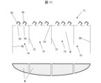
- FIG. 11 is a schematic cross-sectional view of the inner lid 71 showing how the inner lid 71 is cleaned by removing the deposition material M from the inner lid 71.
- the inner lid 71 may be removed from the outer lid 52 after the lid portion 70 is taken out of the vacuum chamber 10.
- the deposition material M is released from the top plate portion 53 by its own weight according to the same principle as that described in the previous embodiment.
- the holes 54 are closed by operating the caps 55, the inner lid 71 is attached to the outer lid 52, and the lid portion 70 is attached inside the vacuum chamber 10, completing the cleaning process of the lid portion 70.
- the deposition material M is partitioned by the partitions 72, and therefore, as shown in FIG. 11, the deposition material M adhered to the top plate portion 53 is divided into multiple parts.
- the lid portion 70 has at least one hole 54 in each of the areas divided by the partitions 72. Therefore, the deposition material M is removed in the cleaning process according to this embodiment by each of the divided deposition material M being detached from the top plate portion 53 due to its own weight. Therefore, compared to the lid portion 50 according to the previous embodiment, the lid portion 70 according to this embodiment can reduce the occurrence of some of the deposition material M remaining without detaching from the top plate portion 53 during the cleaning process.
- the lid portion 70 according to this embodiment has a plurality of holes 54 in at least one of the plurality of regions partitioned by the partition walls 72.
- the lid portion 70 according to this embodiment can reduce the amount of deposition material M remaining in that region during the cleaning process.
- the above-mentioned cleaning process can be performed by opening any one of the holes 54 in each area of the lid portion 70. Therefore, it is sufficient that the lid portion 70 includes at least one hole 54 and a cap 55 that closes each of the holes 54 in an openable and closable manner in each area of the lid portion 70.
- the number of holes 54 located in the first region 73 of the multiple regions of the lid portion 70 is greater than the number of holes 54 located in the second region 74, which has a smaller area of the top plate portion 53 than the first region 73.
- the greater the number of holes 54 per unit area of the top plate portion 53 in each region of the lid portion 70 the more the deposition material M remaining on the top plate portion 53 in that region can be reduced. Therefore, with the above configuration, the lid portion 70 can efficiently reduce the deposition material M remaining on the top plate portion 53 in both the first region 73 and the second region 74.
- a vapor deposition device 1 according to this embodiment differs from the vapor deposition device 1 according to the first embodiment in that the vapor deposition device 1 according to this embodiment includes a lid portion 80 instead of the lid portion 50.
- FIG. 12 is a schematic cross-sectional side view of the lid portion 80 according to this embodiment.
- the lid portion 80 according to this embodiment differs from the lid portion 50 according to the first embodiment only in that it has an inner lid 81 instead of the inner lid 51.
- the inner lid 81 according to this embodiment includes a plurality of bolts 82 instead of the caps 55, compared to the inner lid 51 according to the first embodiment.
- the outer lid 52 supports the inner lid 81 in a detachable manner.
- the bolt 82 can be inserted and removed from each hole 54, and when inserted into each hole 54, it closes the hole 54. Therefore, the bolt 82 functions as a cap that opens and closes each hole 54 by being inserted and removed from each hole 54.
- the manufacturing method of the display device 100 using the deposition device 1 according to this embodiment is the same as the manufacturing method of the display device 100 using the deposition device 1 according to the previous embodiment, except that the lid portion 50 is replaced with the lid portion 80.
- a cleaning process is also performed periodically to clean the lid portion 80, particularly the inner lid 81, and remove the deposition material M accumulated on the underside of the top plate portion 53.
- the cleaning process of the lid portion 80 according to this embodiment is performed in the same manner as the cleaning process of the lid portion 50 according to embodiment 1, except that the operation of the cap 55 is replaced with the insertion and removal of the bolt 82.
- the bolts 82 are pulled out of the holes 54, and the holes 54 are opened, so that the deposition material M adhering to the inner lid 81 is removed from the inner lid 81.
- the bolts 82 are then inserted into the holes 54 to close the holes 54.
- the lid 80 Compared to the lids according to the above-mentioned embodiments, the lid 80 according to this embodiment includes a bolt 82 that opens and closes each hole 54 by inserting and removing it. As a result, the lid 80 can reduce the number of mechanisms for operating the cap and opening and closing each hole 54 through said operation, such as a pivoting mechanism formed on the top plate 53. Therefore, the lid 80 can perform the cleaning process with a simpler configuration, improving maintainability.
Landscapes
- Chemical & Material Sciences (AREA)
- Chemical Kinetics & Catalysis (AREA)
- Engineering & Computer Science (AREA)
- Materials Engineering (AREA)
- Mechanical Engineering (AREA)
- Metallurgy (AREA)
- Organic Chemistry (AREA)
- Physical Vapour Deposition (AREA)
Abstract
蒸着装置(1)は、坩堝(40)と、蓋部(50)と、を備える。蓋部は蒸着材(M)が蒸着対象(X)に到達することを妨げる位置である遮断位置と蒸着材が蒸着対象に到達する開放位置との間を移動する。また、蓋部は、天板部(53)と、少なくとも一つの孔(54)と、少なくとも一つのキャップ(55)と、を含む。天板部は、蓋部が遮断位置にある場合に、坩堝の開口部(42)を蒸着対象が配置される位置からみて開口部と重なる。孔は天板部を連通し、キャップは孔を開閉可能に閉塞する。
Description
本開示は、蒸着膜を形成するための蒸着装置および当該蒸着装置を用いた表示装置の製造方法に関する。
薄膜の形成法として、坩堝中の材料をヒータにて溶融および蒸発させて、坩堝の上方に位置する物体の表面に接触させて凝固させることにより、当該材料を含む薄膜を物体の表面に形成する蒸着法が知られている。特に、OLED等の発光素子を備えた表示装置の製造方法において、発光素子の各層の劣化を低減するために、当該各層の形成に蒸着装置を用いた蒸着法が採用される場合がある。
蒸着装置を用いた蒸着膜の形成工程には、蒸着源を加熱して成膜レートが安定するまでの間、あるいは、真空チャンバ内の基板の変更の間などの、基板に対し蒸着が行われない期間が存在する。当該期間において真空チャンバ内部等の蒸着材による汚染を低減するために、坩堝の開口部を蓋によって覆うことが考えられる。
しかしながら、蒸着膜の形成工程において坩堝の開口部を蓋によって覆う間、蒸着源は昇華しつづけ蓋に付着する。この場合、定期的に蓋を清掃し蓋から蒸着材を除去する整備を行う必要がある。特許文献1は、当該整備の方法として、蓋を回収機構まで移動させたのち蓋を加熱することにより蒸着材を再度蒸発させ、蓋から蒸着材を除去する方法について開示する。
特許文献1に記載されるような方法の場合、蓋の清掃のためには、蓋を回収機構まで移動させ蓋を加熱する工程が必要である。また、当該方法においては、回収機構と、蓋を加熱するためのヒータと、が別途必要となる。このため上記方法では蓋から異物を簡単に除去することが困難であり、蓋の整備性が悪化する。
本開示の一態様に係る蒸着装置は、蒸着材を蒸着対象に向けて放出する開口部を有する坩堝と、前記蒸着材が前記蒸着対象に到達することを妨げる位置である遮断位置と蒸着材が前記蒸着対象に到達する開放位置との間を移動する蓋部と、を備え、前記蓋部は、前記蓋部が前記遮断位置にある場合に前記開口部を前記蒸着対象が配置される位置からみて前記開口部と重なる天板部と、前記天板部を連通する少なくとも一つの孔と、各前記孔を開閉可能に閉塞するキャップと、を含む。
蓋部に付着した蒸着材をより容易に除去でき、蓋部の整備性が改善する。
〔実施形態1〕
<表示装置>
以下、本開示の実施形態について図面を参照しつつ説明する。なお、各図面において、同様の構成については同一の符号を付してその説明を省略する。
<表示装置>
以下、本開示の実施形態について図面を参照しつつ説明する。なお、各図面において、同様の構成については同一の符号を付してその説明を省略する。
本実施形態に係る表示装置について、図2を参照して説明する。図2は本実施形態に係る表示装置100の概略側断面図である。表示装置100は、例えば、テレビまたはスマートフォン等のディスプレイに用いることのできる装置である。表示装置100は、例えばTFT基板である基板101と、基板101上に複数形成された発光素子102と、を備える。
発光素子102は、例えば、基板101の側から順に、第1電極であるアノード103、正孔注入層104、正孔輸送層105、発光層106、電子輸送層107、および第2電極であるカソード108を有する。なお、発光素子102の構造は上記構成に限られず、基板101の側から順に、カソード108、電子輸送層107、発光層106、正孔輸送層105、正孔注入層104、およびアノード103を有してもよい。また、発光素子102は、アノード103とカソード108との間に、少なくとも発光層106を有する限り、正孔注入層104、正孔輸送層105、および、電子輸送層107のうち少なくとも一層を備えていなくともよい。換言すれば、発光素子102は、アノード103とカソード108との間に、少なくとも発光層106を含む機能層を有する。また、発光素子102は、例えば電子輸送層107とカソード108との間の電子注入層を含む、さらなる機能層を有してもよい。
表示装置100は、基板101に形成された不図示のドライバ等を介して各発光素子102のアノード103とカソード108との間に電圧を印加する。電圧を印加された各発光素子102は、アノード103から正孔注入層104および正孔輸送層105を介して発光層106に正孔を注入し、また、カソード108から電子輸送層107を介して発光層106に電子を注入する。発光層106は、例えば有機発光材料を含む発光材料を有し、注入された正孔と電子との再結合により生じた励起子によって発光する。アノード103およびカソード108の少なくとも一方は光透過性である透過電極であり、発光素子102は発光層106から生じた光を透過電極の側に取り出す。これにより、表示装置100は各発光素子102から個々に光を取り出すことにより表示を行う。
本実施形態に係る表示装置100の製造方法としては、例えば、基板101上に発光素子102の各層を順に成膜する方法が挙げられる。ここで、特に本実施形態に係る表示装置100の製造方法においては、発光素子102の各層のうち少なくとも一層は、後述する蒸着装置を用いた蒸着法により成膜される。
<蒸着装置:概要>
本実施形態に係る蒸着装置について図1を参照して説明する。図1は本実施形態に係る蒸着装置1の概略側断面図である。図1は、蒸着装置1によって表面に蒸着膜が形成される後述の蒸着対象X、および蒸着膜の材料であり後述する坩堝本体41の内部に格納される蒸着材Mについても図示している。
本実施形態に係る蒸着装置について図1を参照して説明する。図1は本実施形態に係る蒸着装置1の概略側断面図である。図1は、蒸着装置1によって表面に蒸着膜が形成される後述の蒸着対象X、および蒸着膜の材料であり後述する坩堝本体41の内部に格納される蒸着材Mについても図示している。
蒸着装置1は、真空チャンバ10と、保持部20と、シャッタ30と、坩堝40と、蓋部50と、蓋保持部60と、を備える。
特に、蒸着装置1は、坩堝40と、蓋部50と、を備える。後述の通り、坩堝40は蒸着材Mを蒸着対象Xに向けて放出する開口部42を有する。蓋部50は蒸着材Mが蒸着対象Xに到達することを妨げる位置である遮断位置と蒸着材Mが蒸着対象に到達する開放位置との間を移動する。また、蓋部50は、天板部53と、少なくとも一つの孔54と、少なくとも一つのキャップ55と、を含む。天板部53は、蓋部50が遮断位置にある場合、開口部42を蒸着対象Xが配置される位置からみて開口部42と重なる位置にある。孔54は天板部53を連通し、キャップ55は孔54を開閉可能に閉塞する。上記構成により、本実施形態に係る蒸着装置1は、蓋部50からのより効率的な蒸着材Mの除去を可能とし、蓋部50の整備性を改善する。以下、上記を含め蒸着装置1について詳細に説明する。
<蒸着装置:真空チャンバ>
真空チャンバ10は、筐体11と、第1隔壁12と、第2隔壁13と、第1隔壁開口部14と、第2隔壁開口部15と、を含む。
真空チャンバ10は、筐体11と、第1隔壁12と、第2隔壁13と、第1隔壁開口部14と、第2隔壁開口部15と、を含む。
筐体11は中空であり、第1隔壁12および第2隔壁13は、筐体11の内部において筐体11の底部上面と略平行に延伸し、筐体11の内部を複数の空間に区画する。このため、筐体11の内部は、第1隔壁12よりも上方の第1空間16、第1隔壁12と第2隔壁13との間の第2空間17、および第2隔壁13よりも下方の第3空間18に区画される。
ただし、第1隔壁12には第1隔壁開口部14が形成され、第1隔壁12により区画された第1空間16とは第2空間17とは第1隔壁開口部14を介して連通する。また、第2隔壁13には第2隔壁開口部15が形成される。当該第2隔壁開口部15には後述する坩堝40の開口部42が挿入され密閉される。このため、第2空間17と第3空間18とは連通していない。
筐体11は第1空間16と連通する出入口と、当該出入口を開閉可能に密閉する扉部と、を備えていてもよい。真空チャンバ10の内部には、筐体11の出入口を介して内部に蒸着対象Xが投入されてもよい。真空チャンバ10は、後述する保持部20により蒸着対象Xを第1空間16に保持し、かつ、扉部により出入口を密閉した状態において、不図示のポンプにより筐体11の内部のうち少なくとも第1空間16と第2空間17とを真空とすることができる。筐体11の形状は、第1空間16および第2空間17を真空とした場合における強度維持等の観点から、円筒形状を有してもよいが、これに限られず、直方形状を有してもよい。
<蒸着装置:保持部>
保持部20は、第1空間16に形成されたアーム21を有する。例えば、アーム21は筐体11の上部内面に形成される。蒸着対象Xの蒸着膜を形成する表面を第2空間17の側に向けアーム21上に載置することにより、保持部20は第1空間16において蒸着対象Xを保持する。
保持部20は、第1空間16に形成されたアーム21を有する。例えば、アーム21は筐体11の上部内面に形成される。蒸着対象Xの蒸着膜を形成する表面を第2空間17の側に向けアーム21上に載置することにより、保持部20は第1空間16において蒸着対象Xを保持する。
<蒸着装置:シャッタ>
シャッタ30は、不図示の駆動部により、保持部20に保持された蒸着対象Xから第1隔壁開口部14をみて、第1隔壁開口部14と重なる遮断位置と第1隔壁開口部14と重ならない開放位置との間を移動する。シャッタ30が開放位置にある場合、保持部20に保持された蒸着対象Xは第1隔壁開口部14を介して第2空間17と対向する。なお、本明細書においては特に言及しない限りシャッタ30が開放位置にある場合について説明する。
シャッタ30は、不図示の駆動部により、保持部20に保持された蒸着対象Xから第1隔壁開口部14をみて、第1隔壁開口部14と重なる遮断位置と第1隔壁開口部14と重ならない開放位置との間を移動する。シャッタ30が開放位置にある場合、保持部20に保持された蒸着対象Xは第1隔壁開口部14を介して第2空間17と対向する。なお、本明細書においては特に言及しない限りシャッタ30が開放位置にある場合について説明する。
<蒸着装置:坩堝>
坩堝40は、中空の容器である坩堝本体41と、坩堝本体41の内外を連通する、例えば円筒形状の開口部42と、を含む。本実施形態において坩堝本体41の内部には、例えば昇華性を有し、常温にて固体の蒸着材Mが格納される。坩堝本体41は第3空間18の内部に位置し、また、上述の通り開口部42は第2隔壁開口部15に挿入され第2隔壁開口部15を密閉する。これにより、坩堝本体41の内部と第2空間17とは開口部42を介して連通する。坩堝40は不図示のヒータにより坩堝本体41の内部を加熱することにより、坩堝本体41の内部に格納された蒸着材Mを加熱して昇華させる。開口部42は、坩堝本体41の内部において昇華した蒸着材を第2空間17に向けて、換言すれば蒸着対象Xに向けて蒸着材Mを放出する。坩堝本体41の形状は、円筒形状、直方形状等であってもよく、特に限定されない。坩堝40の各部の材料は例えばチタン等を含むが特に限定されない。
坩堝40は、中空の容器である坩堝本体41と、坩堝本体41の内外を連通する、例えば円筒形状の開口部42と、を含む。本実施形態において坩堝本体41の内部には、例えば昇華性を有し、常温にて固体の蒸着材Mが格納される。坩堝本体41は第3空間18の内部に位置し、また、上述の通り開口部42は第2隔壁開口部15に挿入され第2隔壁開口部15を密閉する。これにより、坩堝本体41の内部と第2空間17とは開口部42を介して連通する。坩堝40は不図示のヒータにより坩堝本体41の内部を加熱することにより、坩堝本体41の内部に格納された蒸着材Mを加熱して昇華させる。開口部42は、坩堝本体41の内部において昇華した蒸着材を第2空間17に向けて、換言すれば蒸着対象Xに向けて蒸着材Mを放出する。坩堝本体41の形状は、円筒形状、直方形状等であってもよく、特に限定されない。坩堝40の各部の材料は例えばチタン等を含むが特に限定されない。
<蒸着装置:蓋部および蓋保持部>
本実施形態に係る蓋部50について、図1に加えて図3を参照し詳細に説明する。図3は、蓋部50の概略断面図であり、特に図1に示す断面のうち蓋部50の近傍について拡大して概略図である。以降、図3を含む概略側断面図は、図1に示す断面と対応する断面について示す。
本実施形態に係る蓋部50について、図1に加えて図3を参照し詳細に説明する。図3は、蓋部50の概略断面図であり、特に図1に示す断面のうち蓋部50の近傍について拡大して概略図である。以降、図3を含む概略側断面図は、図1に示す断面と対応する断面について示す。
蓋部50は、内蓋51と外蓋52とを含む。内蓋51は、天板部53と、複数の孔54と、複数のキャップ55と、天板部53に対する側部56と、を有する。
天板部53は、例えば円板形状を有する板状部材である。孔54のそれぞれは天板部53を連通する。キャップ55は孔54の個数と同数形成され、孔54のそれぞれを開閉可能に閉塞する。換言すれば、本実施形態に係る蓋部50は、複数の孔54と、複数のキャップ55と、を含み、キャップ55のそれぞれは、孔54のそれぞれを開閉可能に閉塞する。キャップ55は、例えば天板部53に回動可能に拘束されてもよい。図1および図3は、全てのキャップ55が対応する孔54を閉塞する状態を図示する。
外蓋52は内蓋51を不図示の支持機構により脱着可能に支持する。特に、外蓋52は内蓋51の天板部53および側部56の外側を覆うように支持する。
蓋部50の各部の材料は特に限定されない。ただし、後述する通り蓋部50の各部に昇華した蒸着材Mが付着した場合等における蓋部50の変形を低減する観点から、蓋部50の各部の材料はSUSを含む低膨張の金属材料を有してもよい。
図1の参照に戻ると、蓋部50は蓋保持部60により真空チャンバ10に対し保持される。蓋保持部60は、例えば、ビーム61と、ビームシャフト62と、を含む。ビーム61は例えば直棒形状を有し、一端に外蓋52が取り付けられる。ビームシャフト62は、例えば第2隔壁13の上面に固定され、ビーム61の外蓋52が取り付けられた側と反対の側の他端を拘束する。特に、ビームシャフト62は、上下方向を軸としてビーム61を回動可能に拘束する。
このため、ビーム61がビームシャフト62の回りに回動することにより、ビーム61に取り付けられた外蓋52が移動する。外蓋52に内蓋51が取り付けられている場合、内蓋51と外蓋52とは共に移動する。これにより、蒸着装置1は、ビーム61のビームシャフト62回りの回動の制御を通じて、蓋部50の位置を制御できる。
例えば、ビーム61は外蓋52と一体であってもよい。また、ビーム61は蓋部50と共にビームシャフト62から取り外し可能であってもよい。
<蒸着装置:蓋部の遮断位置および開放位置>
特に、蓋部50は、蓋保持部60のビーム61の移動に伴って、遮断位置と開放位置との間を移動する。遮断位置と開放位置とについて、図4Aおよび図4Bを参照してより詳細に説明する。図4Aおよび図4Bは、何れも第2空間17を、蒸着対象Xが保持される位置から坩堝40へ向かう方向である図1に示す方向T1に向かってみた場合の概略平面図である。特に図4Aは蓋部50が遮断位置にある場合の第2空間17Aの概略平面図を示し、図4Bは蓋部50が開放位置にある場合の第2空間17Bの概略平面図を示す。
特に、蓋部50は、蓋保持部60のビーム61の移動に伴って、遮断位置と開放位置との間を移動する。遮断位置と開放位置とについて、図4Aおよび図4Bを参照してより詳細に説明する。図4Aおよび図4Bは、何れも第2空間17を、蒸着対象Xが保持される位置から坩堝40へ向かう方向である図1に示す方向T1に向かってみた場合の概略平面図である。特に図4Aは蓋部50が遮断位置にある場合の第2空間17Aの概略平面図を示し、図4Bは蓋部50が開放位置にある場合の第2空間17Bの概略平面図を示す。
蓋部50が遮断位置にある場合、図4Aに示すように、坩堝40の開口部42を蒸着対象Xが配置される位置からみて、換言すれば開口部42を方向T1にみて、蓋部50は開口部42を隠す位置にある。特に、蓋部50が遮断位置にある場合、開口部42を方向T1にみて、天板部53は開口部42と重なる。また、蓋部50が遮断位置にある状態において、外蓋52は内蓋51よりも開口部42と反対の側、換言すれば蒸着対象Xの側において内蓋51を支持する。
このため、蓋部50が遮断位置にある場合、開口部42から放出された蒸着材Mが蒸着対象Xに至るまでの経路上には蓋部50が存在する。したがって、蓋部50の遮断位置とは、蒸着材Mが蒸着対象Xに到達することを蓋部50が妨げる位置である。
ここで、蓋部50が遮断位置にある状態からビーム61がビームシャフト62の回りに回動することにより、蓋部50は遮断位置から図4Bに示す開放位置まで移動する。蓋部50が開放位置にある場合、図4Bに示すように、開口部42を方向T1にみて、蓋部50は開口部42の周囲に位置する。このため、蓋部50が開放位置にある場合、開口部42から放出された蒸着材Mが蒸着対象Xに至るまでの経路上には蓋部50が存在しない。したがって、蓋部50の開放位置とは、開口部42から放出された蒸着材Mが蒸着対象Xに到達する位置である。
<蒸着装置:補記>
蒸着装置1は単一の坩堝40を備えているが、これに限られない。例えば、蒸着装置1は、坩堝本体41の内部に格納される蒸着材Mが含む材料が互いに異なる複数の坩堝40を備えてもよい。この場合、蒸着装置1は坩堝40のそれぞれに対し蓋部50および蓋保持部60を備えてもよい。
蒸着装置1は単一の坩堝40を備えているが、これに限られない。例えば、蒸着装置1は、坩堝本体41の内部に格納される蒸着材Mが含む材料が互いに異なる複数の坩堝40を備えてもよい。この場合、蒸着装置1は坩堝40のそれぞれに対し蓋部50および蓋保持部60を備えてもよい。
蒸着装置1への蒸着対象Xの投入は、例えばコンベア等を含む不図示の搬送装置を用いて行われてもよい。この場合、搬送装置は蒸着対象Xの蒸着膜が形成される面を坩堝40の側に向けつつ真空チャンバ10の内部において蒸着対象Xを搬送するように構成されていてもよい。換言すれば、搬送装置は蒸着材料Xを真空チャンバ10の内部において保持する保持部20の機能を兼ねてよい。
蒸着装置1は、各部の動作を制御する不図示の制御部を備えてもよい。制御部は、例えば、真空チャンバ10の内部の排気、シャッタ30の移動、坩堝40の加熱、および蓋部50の移動を制御してもよい。
<表示装置の製造方法>
図1の参照に戻り本実施形態に係る表示装置100の製造方法について説明する。本実施形態に係る表示装置100の製造方法は、上述の通り、基板101上に発光素子102の各層を順に成膜する工程を含み、発光素子102の各層のうち少なくとも一層は蒸着装置1を用いて成膜される。
図1の参照に戻り本実施形態に係る表示装置100の製造方法について説明する。本実施形態に係る表示装置100の製造方法は、上述の通り、基板101上に発光素子102の各層を順に成膜する工程を含み、発光素子102の各層のうち少なくとも一層は蒸着装置1を用いて成膜される。
特に、発光素子102のうち、正孔注入層104、正孔輸送層105、発光層106、および電子輸送層107を含む機能層が有機材料を含む場合、当該機能層の劣化を低減する観点から、機能層は蒸着法によって成膜されてもよい。また、有機材料を含む層が蒸着された後、当該層上にさらに新たな層の成膜を行う場合にも、既に成膜された層の劣化を低減する観点から、新たな層は蒸着法によって成膜されてもよい。
蒸着装置1を用いた発光素子102の何れかの層の成膜工程においては、例えば、成膜する層より基板101の側の各層までが形成された、基板101を含む積層体を蒸着対象Xとして真空チャンバ10の内部に投入する。ここで積層体は蒸着膜が成膜される面を下側、換言すれば坩堝40の側に向けてアーム21上に載置される。次いで、蒸着装置1は、真空チャンバ10の第1空間16および第2空間17の排気を行い、第1空間16および第2空間17を真空とする。
次いで、蒸着装置1は、成膜する層の材料が蒸着材Mとして坩堝本体41の内部に格納された坩堝40を加熱し、当該蒸着材Mを昇華させる。これにより、坩堝40の内部において昇華した蒸着材Mは坩堝40の開口部42から蒸着対象Xである積層体に向かって放出される。
ここで、蒸着装置1がシャッタ30および蓋部50を共に開放位置とした場合、開口部42から放出された蒸着材Mは積層体の表面に到達する。積層体の表面に到達した蒸着材Mは、積層体の表面との接触により冷却され再び固体となる。これにより、積層体の坩堝40の側の表面には、蒸着材Mを含む蒸着膜が成膜される。
発光素子102の各層のうち、例えばアノード103とカソード108との少なくとも一方、および発光層106は、基板101上のサブ画素ごとに島状に形成されてもよい。この場合、各層の蒸着は、積層体の坩堝40の側に配置され、各サブ画素に対応する位置に開口を有するメタルマスク等の蒸着マスク越しに実行されてもよい。
蒸着装置1が複数の坩堝40を備える場合、上記方法においては、複数の坩堝40を同時に加熱して成膜を行う共蒸着により、複数の材料を含む層を成膜してもよい。
なお、本実施形態に係る表示装置100の製造方法においては、発光素子102の各層の少なくとも一層が蒸着装置1による蒸着法によって成膜されていればよい。例えば、本実施形態に係る表示装置100の製造方法においては、発光素子102の一部の層が、スパッタ法、フォトリソグラフィ法、またはインクジェット法等の蒸着法と異なる方法により成膜されてもよい。
<蓋部の機能>
本実施形態に係る蒸着装置1を用いた蒸着工程において、坩堝40が蒸着材Mを昇華させるために必要なだけ加熱された時点から、開口部42からは昇華した蒸着材Mの放出が開始する。しかしながら、坩堝本体41の内部の加熱の不均一等に起因し、坩堝40が十分に加熱されるまで蒸着対象Xに成膜される蒸着膜の蒸着レートは不安定となる場合がある。蒸着レートとは、例えば、蒸着対象Xに成膜される蒸着膜における、単位時間あたりに成膜される膜厚を指し、蒸着対象Xへの蒸着膜の成膜速度に対応する。
本実施形態に係る蒸着装置1を用いた蒸着工程において、坩堝40が蒸着材Mを昇華させるために必要なだけ加熱された時点から、開口部42からは昇華した蒸着材Mの放出が開始する。しかしながら、坩堝本体41の内部の加熱の不均一等に起因し、坩堝40が十分に加熱されるまで蒸着対象Xに成膜される蒸着膜の蒸着レートは不安定となる場合がある。蒸着レートとは、例えば、蒸着対象Xに成膜される蒸着膜における、単位時間あたりに成膜される膜厚を指し、蒸着対象Xへの蒸着膜の成膜速度に対応する。
蒸着レートを安定させるためには、例えば、坩堝40が十分に加熱されるまで待機することが考えられる。この間、真空チャンバ10の内部の汚損の低減、または蒸着材Mの消費の低減等のため、蒸着装置1は蓋部50を遮断位置に移動させ、昇華した蒸着材Mが蒸着対象Xまで到達することを防止する。坩堝40が十分に加熱されたのち、蒸着装置1は蓋部50を遮断位置から開放位置に移動させ、昇華した蒸着材Mを蒸着対象Xまで到達させる。これにより、蒸着装置1は蒸着レートを安定させつつ蒸着対象Xに成膜される蒸着膜の成膜を実行できる。
遮断位置にある蓋部50が開口部42から放出される蒸着材Mの蒸着対象Xへの到達を遮断する原理について、図5を参照してより詳細に説明する。図5は、蓋部50が遮断位置において坩堝40から放出された蒸着材Mを遮断する様子を表す、坩堝40および蓋部50の概略側断面図である。図示の簡単のため、図5には坩堝40および蓋部50を除く他の蒸着装置1の各部の図示を省略している。
坩堝40が加熱され、坩堝本体41の内部に格納された蒸着材Mが昇華することにより、開口部42からは昇華した蒸着材Mが開口部42から蒸着対象Xへ向かう方向である方向T2に向かって放出される。ここで、蓋部50が遮断位置にある場合、開口部42から方向T2に向かう方向には蓋部50、特に蓋部50の天板部53が位置する。このため、蓋部50が遮断位置にある状態において開口部42から蒸着材Mが放出された場合、放出された蒸着材Mは天板部53に接触し、天板部53において冷却されて固体に戻る。これにより、図5に示すように、蓋部50によって蒸着対象Xへの到達を妨げられた蒸着材Mは、蓋部50に、特に天板部53の下面に固着する。
なお、内蓋51が外蓋52に取り付けられている間、キャップ55は各孔54を閉塞している。このため、坩堝40から放出された蒸着材Mがある孔54に到達した場合においても、蒸着材Mは当該孔54を閉塞するキャップ55の下面に接触する。このため、内蓋51は外蓋52への蒸着材Mの固着を低減する。
また、本実施形態に係る蒸着工程において、蒸着装置1は遮断位置にあるシャッタ30を用いて蒸着対象Xへの蒸着材Mの到達を妨げてもよい。ただし、真空チャンバ10の内部の汚損の低減および真空チャンバ10の清掃の必要性を低減する観点から、蒸着装置1はシャッタ30よりも坩堝40に近接する蓋部50を主に用いて蒸着対象Xへの蒸着材Mの到達を妨げてもよい。
<蓋部の清掃>
蓋部50が遮断位置にある状態における坩堝40の加熱を連続または断続して実行することにより、蒸着材Mは天板部53の下面に蓄積していく。このため、蒸着装置1を使用する場合には、定期的に蓋部50、特に内蓋51の清掃を行い天板部53の下面に蓄積した蒸着材Mを除去する、清掃工程を実行する。これにより、天板部53の下面に蓄積した蒸着材Mが、開口部42と接触することを低減し、あるいは開口部42を閉塞することを低減できる。
蓋部50が遮断位置にある状態における坩堝40の加熱を連続または断続して実行することにより、蒸着材Mは天板部53の下面に蓄積していく。このため、蒸着装置1を使用する場合には、定期的に蓋部50、特に内蓋51の清掃を行い天板部53の下面に蓄積した蒸着材Mを除去する、清掃工程を実行する。これにより、天板部53の下面に蓄積した蒸着材Mが、開口部42と接触することを低減し、あるいは開口部42を閉塞することを低減できる。
蓋部50の清掃工程について図6および図7を参照して詳細に説明する。図6は外蓋52から内蓋51を取り外す様子を示す蓋部50の概略断面図である。図7は内蓋51から蒸着材Mを除去することにより内蓋51を清掃する様子を示す内蓋51の概略断面図である。
蓋部50の清掃工程において、蓋部50は真空チャンバ10の外部に取り出されてもよい。蓋部50の清掃工程においては、例えば、外蓋52と一体のビーム61をビームシャフト62から取り外してもよい。さらに、蓋部50の清掃工程において、図6に示すように、内蓋51は外蓋52から取り外されてもよい。この後、外蓋52には予め蒸着材Mが除去された他の内蓋51が取り付けられてもよく、真空チャンバ10の内部に再度配置されてもよい。これにより、内蓋51を清掃する間においても、蒸着装置1を用いた蒸着工程を実行できる。
蓋部50の清掃工程においては、内蓋51の外蓋52からの取り外しに次いで、図7に示すように、例えばキャップ55を天板部53に対し回動させる等により、孔54を開放する。これにより、天板部53と天板部53に固着した蒸着材Mとの間には、孔54を介して導入された空気が流入する。したがって、キャップ55を操作して孔54を開放することにより、天板部53と蒸着材Mとの間の真空が破れ、図7に示すように、蒸着材Mは自重により天板部53から離脱する。孔54には天板部53の蒸着材Mが付着する面とは反対の側からエアが導入されてもよい。この場合より天板部53からの蒸着材Mの除去を徹底できる。
以上により、天板部53から蒸着材Mを除去することができる。次いで、清掃された内蓋51の各キャップ55の操作により各孔54を閉塞する。次いで、内蓋51を外蓋52に取り付け、さらに当該内蓋51および外蓋52を含む蓋部50を真空チャンバ10の内部に取り付ける。以上により、蓋部50の清掃工程が完了する。
<実施形態1のまとめ>
本実施形態に係る蒸着装置1は、坩堝40から放出された蒸着材Mが蒸着対象Xに到達することを遮断可能な蓋部50を備える。蓋部50は、蒸着材Mを遮断する工程において蒸着材Mが接触し固着する天板部53と、天板部53を連通する孔54と、孔54を開閉可能に閉塞するキャップ55と、を含む。このため、上述の通り、蓋部50の天板部53に蒸着材Mが固着した場合においても、キャップ55を操作し孔54を開放することにより、天板部53に固着した蒸着材Mを一度に多く除去することが可能である。
本実施形態に係る蒸着装置1は、坩堝40から放出された蒸着材Mが蒸着対象Xに到達することを遮断可能な蓋部50を備える。蓋部50は、蒸着材Mを遮断する工程において蒸着材Mが接触し固着する天板部53と、天板部53を連通する孔54と、孔54を開閉可能に閉塞するキャップ55と、を含む。このため、上述の通り、蓋部50の天板部53に蒸着材Mが固着した場合においても、キャップ55を操作し孔54を開放することにより、天板部53に固着した蒸着材Mを一度に多く除去することが可能である。
例えば、蒸着材が固着した蓋部等の物体から蒸着材を除去する他の方法としては、金属製のスプーン等の長尺部材によって物体から蒸着材を直接掻き取る方法が考えられる。当該方法による清掃は、蒸着材を長尺部材により少量ずつ物体から除去する必要があり、清掃に時間が掛かる傾向にある。
また、当該方法においては、蒸着材が長尺部材と接触することにより、回収された蒸着材には長尺部材に含まれる金属等の材料が混入する場合があり、蒸着材の再利用が困難となる。さらに、長尺部材によって蒸着材を物体から直接掻き取る際に当該物体にも長尺部材が接触する可能性があり、物体表面への傷の発生、および、当該傷への長尺部材に含まれる金属等の材料の混入等の問題が生じる場合がある。
本実施形態に係る蒸着装置1は、上述した清掃工程により、一度の多くの蒸着材Mを蓋部50から除去可能であるため、蓋部50に付着した蒸着材Mの除去を容易かつ短時間にて実行することが可能であり、整備性が改善する。また、上記蓋部50の清掃工程はキャップ55を操作するのみにて実行可能であり、蓋部50または蒸着材Mに他部材を接触させる必要がない。したがって、本実施形態に係る蒸着装置1は、蓋部50の清掃工程によって除去した蒸着材Mへの異物の混入を低減し、当該蒸着材Mの再利用を容易とし、また、蓋部50の汚損を低減する。
例えば、蓋部50の内蓋51の内側に固着した蒸着材Mを除去する他の方法としては、側部56に当該側部56を貫通する孔を形成し、当該孔からエアを導入する方法が考えられる。しかしながら、側部56の孔からエアを導入した場合、蒸着材Mと天板部53との間の真空が維持され、蒸着材Mが天板部53に固着したままとなる可能性がある。
本実施形態に係る蓋部50の清掃方法は、側部56の孔からエアを導入する方法と比較して、蒸着材Mと天板部53との間の真空を破壊するため、蒸着材Mが天板部53から離脱しやすくなる。したがって、本実施形態に係る蒸着装置1は、天板部53に孔54を有する蓋部50を備えることにより、側部56に貫通孔を有する蓋部を備える場合と比較してより蓋部50の整備性を改善する。
本実施形態に係る表示装置100の製造方法は、整備性が改善された蒸着装置1を用いて発光素子102の何れかの層を成膜するため、コストおよびタクトタイムを改善する。また、表示装置100の製造方法に用いる蒸着装置1は、蓋部50の汚損を低減するため、当該製造方法は発光素子102への異物の混入を低減し、発光素子102の品質を改善する。
<実施形態1の補記>
本実施形態に係る蓋部50は、蒸着材Mが固着する天板部53を有する内蓋51と、内蓋51を脱着可能に支持する外蓋52と、を含む。このため、本実施形態に係る蒸着装置1は、内蓋51の清掃工程の間においても、外蓋52に他の内蓋51を装着した蓋部50を用いた蒸着工程の実行が可能である。
本実施形態に係る蓋部50は、蒸着材Mが固着する天板部53を有する内蓋51と、内蓋51を脱着可能に支持する外蓋52と、を含む。このため、本実施形態に係る蒸着装置1は、内蓋51の清掃工程の間においても、外蓋52に他の内蓋51を装着した蓋部50を用いた蒸着工程の実行が可能である。
本実施形態に係る蓋部50は、複数の孔54と、複数のキャップ55と、を含み、キャップ55のそれぞれは、孔54のそれぞれを開閉可能に閉塞する。このため、蓋部50の清掃工程において複数の孔54を同時に開放することにより、より確実に蒸着材Mを天板部53から除去できるため、蒸着装置1は清掃工程における蓋部50への蒸着材Mの残存を低減できる。
ただし、上述した清掃工程は、何れかの孔54が開放されることにより実行可能である。したがって、蓋部50は、少なくとも一つの孔54と、当該孔54を開閉可能に閉塞する少なくとも一つのキャップ55と、を含めばよい。
<実施例と比較例との評価>
本実施形態に係る蒸着装置1の整備性について評価するために、実施例に係る蒸着装置と比較例に係る蒸着装置との整備性を比較する。
本実施形態に係る蒸着装置1の整備性について評価するために、実施例に係る蒸着装置と比較例に係る蒸着装置との整備性を比較する。
実施例に係る蒸着装置は、蓋部50を含む、本実施形態に係る蒸着装置1と同一の構成を備える。比較例に係る蒸着装置は、蓋部50として内蓋51のみを備え、外蓋52を備えない。さらに、比較例に係る内蓋51は孔54およびキャップ55を含まない。上記点を除き比較例に係る蒸着装置は本実施形態に係る蒸着装置1と同一の構成を備える。
実施例および比較例のそれぞれにおいては、各蒸着装置を用いた蒸着膜の成膜を、各蓋部50の清掃工程が必要となるまで実行し、次いで蓋部50の清掃工程を実行した。実施例に係る清掃工程においては、上述の通り、外蓋52から内蓋51を取り外し、キャップ55の操作により孔54を開放して、天板部53からの蒸着材Mの除去を行った。比較例に係る清掃工程においては、蓋部50全体を蒸着装置から取り外し、金属製のスプーンを用いて天板部53に付着した蒸着材Mを掻き取ることにより天板部53からの蒸着材Mの除去を行った。
なお、実施例および比較例のそれぞれにおいては、清掃工程に先立って、例えば、蒸着材Mが固着した天板部53を有する内蓋51または蓋部50の重量を測定した。これにより、実施例および比較例のそれぞれにおいて、天板部53に固着した重量を算出した。また、実施例および比較例のそれぞれの清掃工程においては、清掃工程の開始時点からの経過時間を測定しつつ、天板部53から除去された蒸着材Mの重量を測定した。これにより、実施例および比較例のそれぞれの清掃工程において、開始時点からの経過時間ごとに天板部53に固着した蒸着材Mの重量に対する天板部53から除去された蒸着材Mの重量の割合を算出した。
実施例および比較例のそれぞれにおける清掃時間と蒸着材の除去率との関係について図8を参照して説明する。図8は清掃時間と蒸着材の除去率との関係について示すグラフである。図8のグラフにおいて、横軸は清掃時間、換言すれば清掃工程を行う時間(単位:時間)を示し、縦軸は蒸着材除去率、換言すれば天板部53に固着した蒸着材Mの総重量に対する天板部53から除去された蒸着材Mの重量の割合を百分率にて示す。図8のグラフには、実施例における測定値を丸、比較例における測定値を四角にてプロットし、実施例と比較例とのそれぞれのプロットの間の補完線を併せて図示する。
実施例に係る清掃工程においては、開始から30分経過時点において8割以上の蒸着材Mが除去できており、開始から1時間経過以降にはほとんどの蒸着材Mの除去が完了している。一方、比較例に係る清掃工程においては、開始から1時間経過時点においても蒸着材Mの除去率は8割に満たない。したがって、実施例に係る蒸着装置は比較例に係る蒸着装置と比較して、より短時間により多くの蒸着材Mを蓋部50から除去できるため、整備性が改善している。
また、実施例に係る清掃工程において除去した蒸着材Mは他部材との接触が避けられているため、異物が混入した可能性が低く、容易に除去した蒸着材Mの再利用が可能である。一方、比較例に係る清掃工程において除去した蒸着材Mにはスプーンの金属材料の混入の可能性があるため、除去した蒸着材Mの再利用が困難である。
さらに、実施例に係る清掃工程においては天板部53と他部材との接触が避けられているため、天板部53の汚損が低減されている。したがって、当該天板部53を有する内蓋51を再度外蓋52に取り付けた蓋部50を備えた蒸着装置を用いることにより、異物の混入が低減した蒸着膜を成膜できる。一方、比較例に係る清掃工程においては天板部53とスプーンとが接触するため、天板部53が汚損した可能性がある。したがって、当該天板部53を有する蓋部50を備えた蒸着装置を用いた蒸着膜の成膜工程においては、当該蒸着膜への異物の混入の可能性がある。
なお、実施例に係る清掃工程においては、外蓋52から内蓋51を取り外し内蓋の清掃を行うのみであるため、外蓋52に他の内蓋51を装着することにより、清掃工程の間においても蒸着装置を用いた蒸着膜の成膜が実行できる。一方、比較例に係る清掃工程においては、蒸着装置から蓋部50を取り外しているため、清掃工程の間は蒸着装置を用いた蒸着膜の成膜が困難である。
以上より、実施例に係る蒸着装置は比較例に係る蒸着装置と比較して、整備性を改善し、蒸着材の再利用をより容易とし、蒸着膜への異物の混入を低減し、清掃工程と蒸着工程との同時実施をより容易とする。
〔実施形態2〕
<蓋部の隔壁>
本開示の他の実施形態について図面を参照しつつ説明する。本実施形態に係る蒸着装置1は、前実施形態に係る蒸着装置1と比較して、蓋部50に代えて蓋部70を備える点においてのみ構成が異なる。
<蓋部の隔壁>
本開示の他の実施形態について図面を参照しつつ説明する。本実施形態に係る蒸着装置1は、前実施形態に係る蒸着装置1と比較して、蓋部50に代えて蓋部70を備える点においてのみ構成が異なる。
本実施形態に係る蓋部70について図9を参照してより詳細に説明する。図9は本実施形態に係る蓋部70の概略側断面図である。
本実施形態に係る蓋部70は図9に示す通り、前実施形態に係る蓋部50と比較して、内蓋51に代えて内蓋71を備える点においてのみ構成が異なる。本実施形態に係る内蓋71は、前実施形態に係る内蓋51と比較して、天板部53に形成された隔壁72をさらに備える点においてのみ構成が異なる。例えば、本実施形態においても、外蓋52は内蓋71を着脱可能に支持する。
隔壁72は、天板部53に対し側部56が突出する方向と略同一方向に、天板部53から突出する。換言すれば、蓋部70が遮断位置にある状態において、天板部53の開口部42の側の面から突出する。また、隔壁72は、蓋部70が遮断位置にある状態において、開口部42の側の空間を複数の空間に仕切る。
これにより、図9に示すように、蓋部70は隔壁72によって複数の第1の領域73と、複数の第2の領域74と、を含む複数の領域に区画される。ここで、隔壁72によって区画された蓋部70の各領域は、隔壁72または側部56、およびこれらに囲まれた天板部53を含む領域を指す。本実施形態において、各第1の領域73における天板部53の面積は、各第2の領域74における天板部53の面積よりも広い。
さらに、蓋部70は、隔壁72によって区画された複数の領域のそれぞれに少なくとも一つの孔54および当該孔54を開閉可能に閉塞するキャップ55を有する。特に、本実施形態に係る蓋部70は、隔壁72によって区画された複数の領域のうち少なくとも一つにおいて、複数の孔54を有する。例えば、各第1の領域73および各第2の領域74は、複数の孔54および各孔54を開閉可能に閉塞する複数のキャップ55を有する。ここで、各第1の領域73が有する孔54の個数は各第2の領域74が有する孔54の個数よりも多い。
本実施形態に係る蒸着装置1を用いた表示装置100の製造方法は、蓋部50を蓋部70に置き換える点を除き、前実施形態に係る蒸着装置1を用いた表示装置100の製造方法と同一の方法である。このため、本実施形態に係る蒸着装置1を用いた表示装置100の製造方法によっても、蓋部70の内蓋71の天板部53には、蓋部70により蒸着対象Xへの到達が遮断された蒸着材Mが固着する場合がある。
遮断位置にある蓋部70が開口部42から放出される蒸着材Mの蒸着対象Xへの到達を遮断する様子について、図10を参照してより詳細に説明する。図10は、蓋部70が遮断位置において坩堝40から放出された蒸着材Mを遮断する様子を表す、坩堝40および蓋部70の概略側断面図である。図示の簡単のため、図10には坩堝40および蓋部70を除く他の蒸着装置1の各部の図示を省略している。
遮断位置にある蓋部70が開口部42から放出された蒸着材Mを遮断することにより、蓋部50の天板部53への蒸着材Mの固着と同一の原理により、蓋部70の天板部53に蒸着材Mが固着する。ここで、本実施形態において蓋部70により遮断された蒸着材Mは、隔壁72により区画された複数の領域それぞれの天板部53に到達する。このため、蓋部70の天板部53に固着する蒸着材Mは隔壁72によって複数に区画される。
本実施形態に係る蒸着装置1を使用する場合にも、定期的に蓋部70、特に内蓋71の清掃を行い天板部53の下面に蓄積した蒸着材Mを除去する、清掃工程を実行する。蓋部70の清掃工程について図11を参照して詳細に説明する。図11は内蓋71から蒸着材Mを除去することにより内蓋71を清掃する様子を示す内蓋71の概略断面図である。
蓋部70の清掃工程においても、蓋部70を真空チャンバ10の外部に取り出した後、内蓋71を外蓋52から取り外してもよい。次いで、図11に示すように、孔54を開放することにより、前実施形態において説明した原理と同一の原理により、蒸着材Mは自重により天板部53から離脱する。この後、各キャップ55の操作により各孔54を閉塞し、内蓋71を外蓋52に取り付け、蓋部70を真空チャンバ10の内部に取り付けることにより、蓋部70の清掃工程が完了する。
ここで上述の通り蒸着材Mは隔壁72によって区画されているため、図11に示すように、天板部53に固着した蒸着材Mは複数に分割されている。また、蓋部70は隔壁72によって分割された領域のそれぞれに少なくとも一つの孔54を有する。したがって、本実施形態に係る清掃工程における蒸着材Mの除去は、分割された蒸着材Mのそれぞれにかかる自重により蒸着材Mのそれぞれが天板部53から離脱することによる。ゆえに、本実施形態に係る蓋部70は、前実施形態に係る蓋部50と比較して、清掃工程において一部の蒸着材Mが天板部53から離脱せず残存することを低減できる。
特に、本実施形態に係る蓋部70は隔壁72によって区画された複数の領域のうち少なくとも一つに複数の孔54を有する。これにより、本実施形態に係る蓋部70は、清掃工程において、当該領域における蒸着材Mの残存を低減できる。
ただし、上述した清掃工程は、蓋部70の領域のそれぞれにおいて何れか一つの孔54が開放されることにより実行可能である。したがって、蓋部70は、少なくとも一つの孔54と、当該孔54のそれぞれを開閉可能に閉塞するキャップ55と、を蓋部70の各領域に含めばよい。
本実施形態において、蓋部70の複数の領域のうち第1の領域73に位置する孔54の個数は、第1の領域73よりも天板部53の面積が狭い第2の領域74に位置する孔54の個数よりも多い。本実施形態に係る清掃工程においては、蓋部70の各領域における天板部53の単位面積あたりの孔54の個数が多い程、当該領域の天板部53に残存する蒸着材Mを低減できる。したがって、上記構成により、蓋部70は第1の領域73と第2の領域74との双方において、効率よく天板部53に残存する蒸着材Mを低減できる。
〔実施形態3〕
<ボルト>
本開示のさらなる実施形態について図面を参照しつつ説明する。本実施形態に係る蒸着装置1は、実施形態1に係る蒸着装置1と比較して、蓋部50に代えて蓋部80を備える点においてのみ構成が異なる。
<ボルト>
本開示のさらなる実施形態について図面を参照しつつ説明する。本実施形態に係る蒸着装置1は、実施形態1に係る蒸着装置1と比較して、蓋部50に代えて蓋部80を備える点においてのみ構成が異なる。
本実施形態に係る蓋部80について図12を参照してより詳細に説明する。図12は本実施形態に係る蓋部80の概略側断面図である。
本実施形態に係る蓋部80は図12に示す通り、実施形態1に係る蓋部50と比較して、内蓋51に代えて内蓋81を備える点においてのみ構成が異なる。本実施形態に係る内蓋81は、実施形態1に係る内蓋51と比較して、キャップ55に代えてボルト82を複数含む。例えば、本実施形態においても、外蓋52は内蓋81を着脱可能に支持する。
ボルト82は、各孔54に対し抜き差し可能であり、各孔54に挿入することにより当該孔54を閉塞する。このため、ボルト82は各孔54に対し抜き差しされることにより当該孔54を開閉するキャップとして機能する。
本実施形態に係る蒸着装置1を用いた表示装置100の製造方法は、蓋部50を蓋部80に置き換える点を除き、前実施形態に係る蒸着装置1を用いた表示装置100の製造方法と同一の方法である。本実施形態に係る蒸着装置1を使用する場合にも、定期的に蓋部80、特に内蓋81の清掃を行い天板部53の下面に蓄積した蒸着材Mを除去する、清掃工程を実行する。本実施形態に係る蓋部80の清掃工程は、実施形態1に係る蓋部50の清掃工程と比較して、キャップ55の操作をボルト82の抜き差しに置き換える点のみを除き、同一の方法により実行される。
例えば、本実施形態に係る蓋部80の清掃工程においては、各ボルト82を孔54から引き抜き、孔54を開放することにより、内蓋81に付着した蒸着材Mを内蓋81から除去する。上記清掃工程においては、この後各ボルト82を孔54に挿入することにより孔54を閉塞する。
本実施形態に係る蓋部80は、前述の各実施形態に係る蓋部と比較して、抜き差しにより各孔54の開閉を実現するボルト82を含む。このため、蓋部80は、天板部53に形成された回動機構等、キャップの操作および当該操作による各孔54の開閉のための機構を低減できる。したがって、蓋部80はより簡素な構成によって清掃工程を実行でき、整備性を改善する。
本開示は上述した各実施形態に限定されるものではなく、請求項に示した範囲で種々の変更が可能であり、異なる実施形態にそれぞれ開示された技術的手段を適宜組み合わせて得られる実施形態についても本開示の技術的範囲に含まれる。さらに、各実施形態にそれぞれ開示された技術的手段を組み合わせることにより、新しい技術的特徴を形成することができる。
1 蒸着装置
40 坩堝
42 開口部
50 蓋部
51 内蓋
52 外蓋
53 天板部
54 孔
55 キャップ
72 隔壁
73 第1の領域
74 第2の領域
82 ボルト
100 表示装置
102 発光素子
40 坩堝
42 開口部
50 蓋部
51 内蓋
52 外蓋
53 天板部
54 孔
55 キャップ
72 隔壁
73 第1の領域
74 第2の領域
82 ボルト
100 表示装置
102 発光素子
Claims (8)
- 蒸着材を蒸着対象に向けて放出する開口部を有する坩堝と、
前記蒸着材が前記蒸着対象に到達することを妨げる位置である遮断位置と蒸着材が前記蒸着対象に到達する開放位置との間を移動する蓋部と、を備え、
前記蓋部は、
前記蓋部が前記遮断位置にある場合に前記開口部を前記蒸着対象が配置される位置からみて前記開口部と重なる天板部と、
前記天板部を連通する少なくとも一つの孔と、
前記孔を開閉可能に閉塞する少なくとも一つのキャップと、
を含む蒸着装置。 - 前記蓋部は、前記天板部、前記孔、および前記キャップを有する内蓋と、
前記内蓋を着脱可能であり、前記蓋部が前記遮断位置にある状態において前記内蓋よりも前記開口部と反対の側において前記内蓋を支持する外蓋と、を含む請求項1に記載の蒸着装置。 - 前記蓋部は、複数の前記孔と、それぞれが前記孔のそれぞれを開閉可能に閉塞する複数のキャップと、を有する請求項1または2に記載の蒸着装置。
- 前記蓋部は、前記遮断位置にある状態において前記天板部の前記開口部の側の面から突出し、前記開口部の側の空間を複数の空間に仕切る隔壁を有し、
前記蓋部は、前記隔壁によって区画される複数の領域のそれぞれにおいて少なくとも一つの前記孔を有する請求項3に記載の蒸着装置。 - 前記蓋部は、少なくとも一つの前記領域において複数の前記孔を有する請求項4に記載の蒸着装置。
- 前記複数の領域のうち第1の領域に位置する前記孔の個数は、前記複数の領域のうち前記第1の領域よりも前記天板部の面積が狭い第2の領域に位置する前記孔の個数よりも多い請求項5に記載の蒸着装置。
- 前記キャップは、前記孔に挿入することにより前記孔を閉塞する請求項1から6の何れか1項に記載の蒸着装置。
- 第1電極、第2電極、および前記第1電極と前記第2電極との間の少なくとも発光層を含む機能層をそれぞれ有する複数の発光素子を備えた表示装置の製造方法であって、
前記第1電極、前記第2電極、および前記機能層のうち少なくとも一層を請求項1から7の何れか1項に記載の蒸着装置を用いて成膜する表示装置の製造方法。
Priority Applications (1)
| Application Number | Priority Date | Filing Date | Title |
|---|---|---|---|
| PCT/JP2023/011687 WO2024201547A1 (ja) | 2023-03-24 | 2023-03-24 | 蒸着装置、表示装置の製造方法 |
Applications Claiming Priority (1)
| Application Number | Priority Date | Filing Date | Title |
|---|---|---|---|
| PCT/JP2023/011687 WO2024201547A1 (ja) | 2023-03-24 | 2023-03-24 | 蒸着装置、表示装置の製造方法 |
Publications (1)
| Publication Number | Publication Date |
|---|---|
| WO2024201547A1 true WO2024201547A1 (ja) | 2024-10-03 |
Family
ID=92904130
Family Applications (1)
| Application Number | Title | Priority Date | Filing Date |
|---|---|---|---|
| PCT/JP2023/011687 Ceased WO2024201547A1 (ja) | 2023-03-24 | 2023-03-24 | 蒸着装置、表示装置の製造方法 |
Country Status (1)
| Country | Link |
|---|---|
| WO (1) | WO2024201547A1 (ja) |
Citations (4)
| Publication number | Priority date | Publication date | Assignee | Title |
|---|---|---|---|---|
| JPH05166725A (ja) * | 1991-12-11 | 1993-07-02 | Japan Steel Works Ltd:The | 成膜装置用シャッター |
| JP2005149924A (ja) * | 2003-11-17 | 2005-06-09 | Toray Ind Inc | 蒸着装置および蒸着材料の回収・再利用方法並びに有機電界発光装置の製造方法。 |
| JP2014181359A (ja) * | 2013-03-18 | 2014-09-29 | Fujitsu Ltd | 半導体製造装置及びシャッタ |
| JP2019081949A (ja) * | 2017-10-31 | 2019-05-30 | キヤノントッキ株式会社 | 蒸発源装置、成膜装置、成膜方法、および、電子デバイスの製造方法 |
-
2023
- 2023-03-24 WO PCT/JP2023/011687 patent/WO2024201547A1/ja not_active Ceased
Patent Citations (4)
| Publication number | Priority date | Publication date | Assignee | Title |
|---|---|---|---|---|
| JPH05166725A (ja) * | 1991-12-11 | 1993-07-02 | Japan Steel Works Ltd:The | 成膜装置用シャッター |
| JP2005149924A (ja) * | 2003-11-17 | 2005-06-09 | Toray Ind Inc | 蒸着装置および蒸着材料の回収・再利用方法並びに有機電界発光装置の製造方法。 |
| JP2014181359A (ja) * | 2013-03-18 | 2014-09-29 | Fujitsu Ltd | 半導体製造装置及びシャッタ |
| JP2019081949A (ja) * | 2017-10-31 | 2019-05-30 | キヤノントッキ株式会社 | 蒸発源装置、成膜装置、成膜方法、および、電子デバイスの製造方法 |
Similar Documents
| Publication | Publication Date | Title |
|---|---|---|
| US9909205B2 (en) | Vapor deposition apparatus, vapor deposition method using vapor deposition apparatus, and device production method | |
| US8802200B2 (en) | Method and apparatus for cleaning organic deposition materials | |
| US20170022605A1 (en) | Deposition apparatus, method for controlling same, deposition method using deposition apparatus, and device manufacturing method | |
| KR101248314B1 (ko) | 성막 장치 및 성막 방법 | |
| JP2012211352A (ja) | 蒸発源並びに有機elデバイス製造装置及び有機elデバイス製造方法 | |
| US9174250B2 (en) | Method and apparatus for cleaning organic deposition materials | |
| JP2011127137A (ja) | 蒸着坩堝及び蒸着装置 | |
| WO2024201547A1 (ja) | 蒸着装置、表示装置の製造方法 | |
| JP2006104497A (ja) | 蒸着装置 | |
| JP7688523B2 (ja) | 成膜装置及び電子デバイスの製造方法 | |
| JP7702815B2 (ja) | 成膜装置及び電子デバイスの製造方法 | |
| KR20140025795A (ko) | 선택적 선형 증발 장치 | |
| JP2011122199A (ja) | 蒸着装置 | |
| JP4557710B2 (ja) | 成膜装置及び蒸着装置 | |
| JP3791450B2 (ja) | 有機薄膜の蒸着方法 | |
| JP3428057B2 (ja) | 連続真空蒸着装置 | |
| KR20050053448A (ko) | 진공 성막 장치 | |
| TW201333231A (zh) | 用於連續沉積薄膜的設備 | |
| JP2011094197A (ja) | 蒸着装置及び有機エレクトロルミネッセンス装置の製造装置 | |
| KR100696531B1 (ko) | 가열용기와 이를 이용한 증착장치 | |
| CN116219368B (zh) | 蒸镀用坩埚及蒸镀装置 | |
| JP2003115379A (ja) | 有機el素子製造装置 | |
| JP2005236093A (ja) | 気相成長装置 | |
| JP2007113077A (ja) | 坩堝 | |
| WO2025220066A1 (ja) | 蒸着装置、表示装置の製造方法 |
Legal Events
| Date | Code | Title | Description |
|---|---|---|---|
| 121 | Ep: the epo has been informed by wipo that ep was designated in this application |
Ref document number: 23930189 Country of ref document: EP Kind code of ref document: A1 |
|
| NENP | Non-entry into the national phase |
Ref country code: DE |
|
| 122 | Ep: pct application non-entry in european phase |
Ref document number: 23930189 Country of ref document: EP Kind code of ref document: A1 |