WO2024195851A1 - 電動車両の制御システム - Google Patents
電動車両の制御システム Download PDFInfo
- Publication number
- WO2024195851A1 WO2024195851A1 PCT/JP2024/011207 JP2024011207W WO2024195851A1 WO 2024195851 A1 WO2024195851 A1 WO 2024195851A1 JP 2024011207 W JP2024011207 W JP 2024011207W WO 2024195851 A1 WO2024195851 A1 WO 2024195851A1
- Authority
- WO
- WIPO (PCT)
- Prior art keywords
- motor
- output
- control device
- engine
- charging rate
- Prior art date
- Legal status (The legal status is an assumption and is not a legal conclusion. Google has not performed a legal analysis and makes no representation as to the accuracy of the status listed.)
- Ceased
Links
Images


Classifications
-
- B—PERFORMING OPERATIONS; TRANSPORTING
- B60—VEHICLES IN GENERAL
- B60K—ARRANGEMENT OR MOUNTING OF PROPULSION UNITS OR OF TRANSMISSIONS IN VEHICLES; ARRANGEMENT OR MOUNTING OF PLURAL DIVERSE PRIME-MOVERS IN VEHICLES; AUXILIARY DRIVES FOR VEHICLES; INSTRUMENTATION OR DASHBOARDS FOR VEHICLES; ARRANGEMENTS IN CONNECTION WITH COOLING, AIR INTAKE, GAS EXHAUST OR FUEL SUPPLY OF PROPULSION UNITS IN VEHICLES
- B60K6/00—Arrangement or mounting of plural diverse prime-movers for mutual or common propulsion, e.g. hybrid propulsion systems comprising electric motors and internal combustion engines
- B60K6/20—Arrangement or mounting of plural diverse prime-movers for mutual or common propulsion, e.g. hybrid propulsion systems comprising electric motors and internal combustion engines the prime-movers consisting of electric motors and internal combustion engines, e.g. HEVs
- B60K6/42—Arrangement or mounting of plural diverse prime-movers for mutual or common propulsion, e.g. hybrid propulsion systems comprising electric motors and internal combustion engines the prime-movers consisting of electric motors and internal combustion engines, e.g. HEVs characterised by the architecture of the hybrid electric vehicle
- B60K6/44—Series-parallel type
-
- B—PERFORMING OPERATIONS; TRANSPORTING
- B60—VEHICLES IN GENERAL
- B60W—CONJOINT CONTROL OF VEHICLE SUB-UNITS OF DIFFERENT TYPE OR DIFFERENT FUNCTION; CONTROL SYSTEMS SPECIALLY ADAPTED FOR HYBRID VEHICLES; ROAD VEHICLE DRIVE CONTROL SYSTEMS FOR PURPOSES NOT RELATED TO THE CONTROL OF A PARTICULAR SUB-UNIT
- B60W10/00—Conjoint control of vehicle sub-units of different type or different function
- B60W10/04—Conjoint control of vehicle sub-units of different type or different function including control of propulsion units
- B60W10/06—Conjoint control of vehicle sub-units of different type or different function including control of propulsion units including control of combustion engines
-
- B—PERFORMING OPERATIONS; TRANSPORTING
- B60—VEHICLES IN GENERAL
- B60W—CONJOINT CONTROL OF VEHICLE SUB-UNITS OF DIFFERENT TYPE OR DIFFERENT FUNCTION; CONTROL SYSTEMS SPECIALLY ADAPTED FOR HYBRID VEHICLES; ROAD VEHICLE DRIVE CONTROL SYSTEMS FOR PURPOSES NOT RELATED TO THE CONTROL OF A PARTICULAR SUB-UNIT
- B60W10/00—Conjoint control of vehicle sub-units of different type or different function
- B60W10/04—Conjoint control of vehicle sub-units of different type or different function including control of propulsion units
- B60W10/08—Conjoint control of vehicle sub-units of different type or different function including control of propulsion units including control of electric propulsion units, e.g. motors or generators
-
- B—PERFORMING OPERATIONS; TRANSPORTING
- B60—VEHICLES IN GENERAL
- B60W—CONJOINT CONTROL OF VEHICLE SUB-UNITS OF DIFFERENT TYPE OR DIFFERENT FUNCTION; CONTROL SYSTEMS SPECIALLY ADAPTED FOR HYBRID VEHICLES; ROAD VEHICLE DRIVE CONTROL SYSTEMS FOR PURPOSES NOT RELATED TO THE CONTROL OF A PARTICULAR SUB-UNIT
- B60W10/00—Conjoint control of vehicle sub-units of different type or different function
- B60W10/24—Conjoint control of vehicle sub-units of different type or different function including control of energy storage means
- B60W10/26—Conjoint control of vehicle sub-units of different type or different function including control of energy storage means for electrical energy, e.g. batteries or capacitors
-
- B—PERFORMING OPERATIONS; TRANSPORTING
- B60—VEHICLES IN GENERAL
- B60W—CONJOINT CONTROL OF VEHICLE SUB-UNITS OF DIFFERENT TYPE OR DIFFERENT FUNCTION; CONTROL SYSTEMS SPECIALLY ADAPTED FOR HYBRID VEHICLES; ROAD VEHICLE DRIVE CONTROL SYSTEMS FOR PURPOSES NOT RELATED TO THE CONTROL OF A PARTICULAR SUB-UNIT
- B60W20/00—Control systems specially adapted for hybrid vehicles
- B60W20/10—Controlling the power contribution of each of the prime movers to meet required power demand
- B60W20/15—Control strategies specially adapted for achieving a particular effect
- B60W20/16—Control strategies specially adapted for achieving a particular effect for reducing engine exhaust emissions
Definitions
- This disclosure relates to a control system for an electric vehicle.
- Patent Document 1 avoids a decline in the power performance of the electric vehicle by assisting the engine output with a motor.
- assisting the engine output with a motor increases power consumption.
- the amount of power generated also decreases due to the decline in engine output. Therefore, depending on the charge level of the battery, there may be cases where assistance by the motor is not possible.
- the objective of this disclosure is to provide a control system for electric vehicles that prioritizes suppressing emissions deterioration.
- the control system for an electric vehicle includes a motor that drives the wheels of the electric vehicle, an engine having a catalyst that purifies exhaust, a drive battery that supplies power to the first rotating electric machine, and a control device that controls the electric vehicle, and when it is necessary to increase the temperature of the catalyst, the control device executes engine output limiting control that increases the temperature of the catalyst while limiting the engine to a predetermined output, and motor output limiting control that controls the motor while limiting the output of the motor.
- the control system for this electric vehicle prioritizes preventing emissions deterioration over reducing power performance by implementing engine output limit control and motor output limit control.
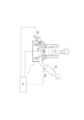
- FIG. 1 is a system diagram of an electric vehicle according to one embodiment of the present disclosure.
- FIG. 1 is a system diagram of an engine according to one embodiment of the present disclosure.
- 4 is a flowchart showing a control procedure executed by a control device according to an embodiment of the present disclosure.
- 5 is a sub-flowchart showing a control procedure executed by a control device according to an embodiment of the present disclosure.
- 4 is a timing chart illustrating an example of a control procedure executed by a control device according to an embodiment of the present disclosure.
- the control system 3 of the electric vehicle C includes an engine 1, a motor (FrM) 2, a generator (GEN) 4, a drive battery (BT) 6, and a vehicle control device (an example of a control device) 12.
- the control system 3 of the electric vehicle C in this embodiment is a hybrid vehicle or a plug-in hybrid vehicle (PHEV) that uses the engine 1 and the motor 2 as power sources to drive the wheels C1.
- the control system 3 of the electric vehicle C of this embodiment further includes a transaxle 8.
- the transaxle 8 has a plurality of gears and a clutch 8a.
- the engine 1 is connected to the generator 4 and the axle 10 via the transaxle 8.
- the transaxle 8 cuts off the power transmission between the engine 1 and the axle 10.
- the transaxle 8 transmits the power of the engine 1 to the axle 10.
- the motor 2 is connected to the axle 10 via the transaxle 8.
- the electric vehicle C may also include a vehicle control device 12, an engine control device 14 that controls the engine 1, an accelerator pedal 16 operated by a user of the electric vehicle C, an inverter 18 that controls the motor 2 and the generator 4, a charging button (not shown), and a power supply button (not shown).
- the electric vehicle C is a plug-in hybrid vehicle that has a charger 20 that can be connected to an external power source and a power supply device 22 that can supply power from the drive battery 6 to external devices such as home appliances.
- the electric vehicle C may be a hybrid vehicle that does not have such devices.
- the electric vehicle C of this embodiment has various modes, such as EV mode, series mode, parallel mode, charging mode, and power supply mode.
- EV mode the electric vehicle C drives the motor 2 with power from the drive battery 6.
- series mode the electric vehicle C drives the generator 4 with the engine 1 and drives the motor 2 with the power generated by the generator 4.
- parallel mode the electric vehicle C connects the clutch 8a and drives the axle 10 with the power of the engine 1.
- charging mode the electric vehicle C drives the generator 4 with the engine 1 and stores the power generated by the generator 4 in the drive battery 6.
- the vehicle control device 12 switches between each mode depending on the depression state of the accelerator pedal 16 or the operation state of the charge button or power supply button, controls the motor 2 and generator 4 via the inverter 18, and has the engine control device 14 control the engine 1.
- the engine 1 includes a fuel injection valve 30, a spark plug 32, and a catalyst 34.
- the engine 1 is a gasoline engine in which the spark plug 32 ignites a mixture of fuel injected from the fuel injection valve 30 and intake air.
- the catalyst 34 is a three-way catalyst that purifies the exhaust gas of the gasoline engine.
- the engine 1 may further include a temperature sensor 36.
- the temperature sensor 36 may detect the temperature of the catalyst 34 (hereinafter referred to as catalyst temperature Tc in the specification).
- the purification performance of the catalyst 34 differs depending on the catalyst temperature Tc. As shown by the catalyst temperature Tc in the timing chart of FIG. 5, the catalyst 34 is in a state where the purification performance of the catalyst 34 reaches about 50% at a first catalyst temperature (one example of a predetermined temperature) T1 (hereinafter referred to as a semi-active state in the specification). The catalyst 34 is in a state where the purification performance of the catalyst 34 reaches about 80% at a second catalyst temperature T2 higher than the first catalyst temperature T1 (hereinafter referred to as an active state in the specification). In this embodiment, the first catalyst temperature T1 is about 150°C to 180°C. The second catalyst temperature is about 300°C to 360°C. In this embodiment, the purification performance of the catalyst 34 is close to 100% when the catalyst temperature Tc is about 700°C. The catalyst 34 is in an inactive state where the purification performance is less than 50% below the first catalyst temperature T1.
- a first catalyst temperature one example of a predetermined temperature
- T1 one example of
- the generator 4 is connected to the engine 1 and is capable of driving the engine 1.
- the generator 4 performs motoring to drive the engine 1 while the engine 1 is being powered by electric power from the drive battery 6.
- the generator 4 is driven by the engine 1 to generate electricity while the engine 1 is in operation. Therefore, the generator 4 is a motor-generator capable of powering and generating electricity.
- the drive battery 6 has a battery module that includes multiple battery cells that are made up of secondary batteries such as lithium-ion batteries.
- the drive battery 6 also has a battery monitoring unit (BMU) 6a.
- the battery monitoring unit 6a calculates the state of charge (State of Charge, hereafter referred to as SOC) of the battery module as an example of the charge state of the drive battery 6.
- SOC state of charge
- the battery monitoring unit 6a may detect the deterioration state (State of Health, hereafter referred to as SOH) of the battery module and the battery temperature Tb.
- SOH deterioration state
- the battery monitoring unit 6a acquires the charge rate SOC, the deterioration state SOH, and the battery temperature Tb, and transmits them to the vehicle control device 12.
- the vehicle control device 12 is electrically connected to the motor 2 and the generator 4 via the inverter 18, and controls the motor 2 and the generator 4.
- the vehicle control device 12 also executes at least the following controls: normal operation, motor output limit control, and engine output limit control. Furthermore, the vehicle control device 12 of this embodiment transmits an instruction for engine output limit control to the engine control device 14, and causes the engine control device 14 to control the engine 1.
- the vehicle control device 12 is an ECU (Electronic Control Unit) that is composed of a microcomputer including a calculation device, a memory, an input/output buffer, and the like. The vehicle control device 12 executes various controls of the electric vehicle C based on the maps and programs stored in the memory.
- the vehicle control device 12 is also electrically connected to the battery monitoring unit 6a of the drive battery 6, and can acquire information such as the charging rate SOC and battery temperature Tb of the drive battery 6.
- the vehicle control device 12 controls the motor 2 and the engine 1 during normal operation to achieve the required output PW, which will be described later. Specifically, the vehicle control device 12 determines the motor required output PWm of the motor 2 and the engine required output PWe of the engine 1 based on the required output PW. The vehicle control device 12 controls the motor 2 so that the output of the motor 2 becomes the motor required output PWm. The vehicle control device 12 causes the engine control device 14 to control the engine 1 so that the output of the engine 1 becomes the engine required output PWe. During normal operation, the vehicle control device 12 selects one of the EV mode, series mode, and parallel mode according to the charging rate SOC, the required output PW, and the vehicle speed V to control the electric vehicle C. On the other hand, when either the motor output limit control or the engine output limit control is executed, the vehicle control device 12 releases the clutch 8a and controls the electric vehicle C in the series mode.
- the vehicle control device 12 controls the motor 2 while limiting the output of the motor 2 in the motor output limit control. Specifically, the vehicle control device 12 limits the output of the motor 2 to a value lower than the motor required output PWm. In this embodiment, the vehicle control device 12 executes the output limit of the motor 2 in at least four stages from the first level to the fourth level. In the first level, the vehicle control device 12 limits the output of the motor 2 to the first output limit value PR1, which is the lowest of the four stages (an example of the first motor output limit control). In the third level, the vehicle control device 12 limits the output of the motor 2 to the third output limit value PR3, which is higher than the first output limit value PR1 and lower than the second output limit value PR2 (an example of the third motor output limit control).
- the vehicle control device 12 limits the output of the motor 2 to the second output limit value PR2, which is higher than the third output limit value PR3 and lower than the fourth output limit value PR4 (an example of the second motor output limit control).
- the vehicle control device 12 limits the output of the motor 2 to the fourth output limit value PR4, which is the highest of the four levels (an example of fourth motor output limit control).
- the engine control device 14 is electrically connected to at least the fuel injection valve 30 and the spark plug 32, and is a control device that controls the engine 1.
- the engine control device 14 is actually an ECU (Electronic Control Unit) that is composed of a microcomputer including an arithmetic unit, memory, input/output buffers, etc.
- the engine control device 14 executes various controls of the engine 1 based on maps and programs stored in the memory. Note that the control of the engine 1 may be executed by the vehicle control device 12 in addition to the engine control device 14.
- the engine control device 14 When the engine control device 14 receives an instruction for engine output limit control, it executes a catalyst warm-up operation to warm up the catalyst 34 while raising the temperature of the catalyst 34. During this operation, the engine control device 14 estimates the catalyst temperature Tc from the operating state of the engine 1. Note that, if the engine 1 is equipped with a temperature sensor 36, the engine control device 14 may obtain the catalyst temperature Tc from the temperature sensor 36. When the engine control device 14 obtains the catalyst temperature Tc, it transmits the catalyst temperature Tc to the vehicle control device 12.
- the engine control device 14 limits the output of the engine 1 to a predetermined output so that the engine is in an operating state in which the temperature of the catalyst 34 is easily increased. Specifically, in engine output limiting control, the engine control device 14 retards the ignition timing of the spark plug 32. This increases the exhaust temperature, making it easier to increase the catalyst temperature Tc of the catalyst 34. However, if the engine required output PWe increases when the ignition timing is retarded, the amount of fuel injected by the fuel injection valve 30 increases, and the combustion state of the engine 1 may become unstable. To prevent such an unstable combustion state, the engine control device 14 limits the output of the engine 1 to a predetermined output at which combustion can be stabilized when the ignition timing is retarded. In this way, the engine control device 14 prioritizes the increase in temperature of the catalyst 34 by limiting the output of the engine 1 to a predetermined output.
- the vehicle control device 12 starts the control procedure when an ignition switch (not shown) is turned on.
- step S1 the vehicle control device 12 acquires the accelerator opening Th, which is the opening of the accelerator pedal 16.
- the vehicle control device 12 also acquires the vehicle speed V, which is the speed of the electric vehicle C, by calculation from the rotation of the wheel C1.
- the vehicle control device 12 proceeds to step S2.
- step S2 the vehicle control device 12 calculates the required output PW, which is the output required of the electric vehicle C, from the accelerator opening Th and the vehicle speed V. After calculating the required output PW, the vehicle control device 12 proceeds to step S3.
- step S3 the vehicle control device 12 obtains the catalyst temperature Tc of the catalyst 34 and proceeds to step S4.
- step S4 the vehicle control device 12 determines whether the catalyst temperature Tc is less than the second catalyst temperature T2. That is, the vehicle control device 12 determines whether the catalyst 34 has not reached an active state and whether it is necessary to increase the temperature of the catalyst 34. If the vehicle control device 12 determines that the catalyst temperature Tc is less than the second catalyst temperature T2 (step S4 YES), it determines that it is necessary to increase the temperature of the catalyst 34 and proceeds to step S5.
- step S5 the vehicle control device 12 determines whether the catalyst temperature Tc is less than the first catalyst temperature T1. That is, the vehicle control device 12 determines whether the catalyst 34 has reached a semi-active state. If the vehicle control device 12 determines that the catalyst temperature Tc is less than the first catalyst temperature T1 (step S5 YES), it determines that the catalyst 34 has not reached a semi-active state and proceeds to step S6.
- step S6 the vehicle control device 12 determines whether the charging rate SOC is less than the first charging rate SOC1.
- the first charging rate SOC1 is the charging rate SOC at which the motor 2 can be operated at the motor required output PWm. More specifically, the first charging rate SOC1 is the charging rate SOC at which the drive battery 6 can supply power corresponding to the motor required output PWm to the motor 2.
- the first charging rate SOC1 is, for example, a charging rate SOC between 50 percent and 60 percent. If the vehicle control device 12 determines that the charging rate SOC is less than the first charging rate SOC1 (step S6 YES), the process proceeds to step S7.
- step S7 the vehicle control device 12 determines whether the charging rate SOC is less than a second charging rate (an example of a predetermined charging rate) SOC2.
- the second charging rate SOC2 is the charging rate SOC at which the motor 2 can be operated at the second output limit value PR2. More specifically, the second charging rate SOC2 is the charging rate SOC at which the drive battery 6 can supply power corresponding to the second output limit value PR2 to the motor 2.
- the second charging rate SOC2 is, for example, a charging rate SOC between 30 percent and 40 percent. If the vehicle control device 12 determines that the charging rate SOC is less than the second charging rate SOC2 (step S7 YES), the process proceeds to step S8.
- step S8 the vehicle control device 12 executes engine output limit control and proceeds to step S9.
- step S9 the vehicle control device 12 executes a first level of motor output limit control. That is, when the motor required output PWm exceeds the first output limit value PR1, the vehicle control device 12 controls the motor 2 while limiting the output of the motor 2 to the first output limit value PR1 as motor output limit control. After executing the process of step S9, the vehicle control device 12 proceeds to step S1.
- step S4 NO If the vehicle control device 12 determines in step S4 that the catalyst temperature Tc is equal to or higher than the second catalyst temperature T2 (step S4 NO), the vehicle control device 12 proceeds to step S14 and executes control under normal operation. In other words, the vehicle control device 12 does not execute engine output limit control or motor output limit control.
- step S5 NO If the vehicle control device 12 determines in step S5 that the catalyst temperature Tc is equal to or higher than the first catalyst temperature T1 (step S5 NO), the vehicle control device 12 advances the process to A in FIG. 3, and then to the sub-flowchart in FIG. 4. The sub-flowchart in FIG. 4 will be described later.
- step S6 determines in step S6 that the charging rate SOC is equal to or higher than the first charging rate SOC1 (step S6 NO)
- step S10 determines in step S6 that the charging rate SOC is equal to or higher than the first charging rate SOC1
- step S10 the vehicle control device 12 executes engine output limiting control and proceeds to step S11.
- step S11 the vehicle control device 12 operates the motor 2 at normal output. In other words, the vehicle control device 12 controls the output of the motor 2 to be the motor required output PWm. After executing the process of step S22, the vehicle control device 12 proceeds to step S1.
- step S7 determines in step S7 that the charging rate SOC is equal to or higher than the second charging rate SOC2 (step S7 NO)
- step S7 NO the vehicle control device 12 proceeds to step S12.
- step S12 the vehicle control device 12 executes engine output limit control and proceeds to step S13.
- step S13 the vehicle control device 12 executes a second level of motor output limit control. That is, when the motor required output PWm exceeds the second output limit value PR2, the vehicle control device 12 controls the motor 2 while limiting the output of the motor 2 to the second output limit value PR2. After executing the process of step S13, the vehicle control device 12 proceeds to step S1.
- the sub-flowchart shows the control procedure after the catalyst 34 reaches a semi-active state.
- step S21 the vehicle control device 12 determines whether the charging rate SOC is less than the first charging rate SOC1.
- the first charging rate SOC1 is the same value as in step S6. If the vehicle control device 12 determines that the charging rate SOC is less than the first charging rate SOC1 (step S21 YES), the process proceeds to step S22.
- step S22 the vehicle control device 12 determines whether the charging rate SOC is less than the third charging rate SOC3.
- the third charging rate SOC3 is the charging rate SOC at which the motor 2 can be operated at the fourth output limit value PR4. More specifically, the third charging rate SOC3 is the charging rate SOC at which the drive battery 6 can supply power corresponding to the fourth output limit value PR4 to the motor 2.
- the third charging rate SOC3 is, for example, a charging rate SOC between 60 percent and 70 percent. If the vehicle control device 12 determines that the charging rate SOC is less than the third charging rate SOC3 (YES in step S22), the process proceeds to step S23.
- step S23 the vehicle control device 12 executes engine output limit control and proceeds to step S24.
- step S24 the vehicle control device 12 executes a third level of motor output limit control. That is, when the motor required output PWm exceeds the third output limit value PR3, the vehicle control device 12 controls the motor 2 while limiting the output of the motor 2 to the third output limit value PR3. After executing the processing of step S24, the vehicle control device 12 proceeds to step S1 (see FIG. 3).
- step S21 determines in step S21 that the charging rate SOC is equal to or higher than the first charging rate SOC1 (step S21 NO)
- step S21 NO the vehicle control device 12 proceeds to step S25.
- step S25 the vehicle control device 12 executes engine output limiting control and proceeds to step S26.
- step S26 the vehicle control device 12 operates the motor 2 at normal output, similar to step S11. After executing the process of step S26, the vehicle control device 12 proceeds to step S1 (see FIG. 3).
- step S22 determines in step S22 that the charging rate SOC is equal to or higher than the third charging rate SOC3 (step S22 NO)
- step S27 the vehicle control device 12 proceeds to step S27.
- step S27 the vehicle control device 12 executes engine output limit control and proceeds to step S28.
- step S28 the vehicle control device 12 executes a fourth level of motor output limit control. That is, when the motor required output PWm exceeds the fourth output limit value PR4, the vehicle control device 12 controls the motor 2 while limiting the output of the motor 2 to the fourth output limit value PR4. After executing the processing of step S28, the vehicle control device 12 proceeds to step S1 (see FIG. 3).
- the vehicle control device 12 calculates the motor required output PWm and the engine required output PWe based on the calculated required output PW (see steps S1 and S2 in Figure 3).
- the vehicle control device 12 controls the motor 2 so that the output of the motor 2 becomes the motor required output PWm without limiting the output of the motor 2. Therefore, as shown by the vehicle speed V, the vehicle speed V during this period follows the accelerator opening Th. At this time, the amount of power generation by the engine 1 is limited by the engine output limit control, so the charging rate SOC is more likely to decrease than when the engine output limit control is not being executed.
- the vehicle control device 12 limits the output of the motor 2 to the second output limit value PR2. At this time, if the motor required output PWm is higher than the second output limit value PR2, the vehicle control device 12 limits the output of the motor 2 to the second output limit value PR2.
- the vehicle control device 12 limits the output of the motor 2 to the first output limit value PR1.
- the vehicle control device 12 sets the first output limit value PR1 so that the charging rate SOC is constant at a fourth charging rate SOC4 that has a predetermined margin with respect to the allowable lower limit charging rate SOCmin, which is the allowable lower limit charging rate SOC of the drive battery 6.
- the motor 2 is driven by the power generated by the generator 4 driven by the engine 1.
- the engine 1 is operated at a predetermined output. Therefore, in this embodiment, the first output limit value PR1 is a value determined by the amount of power generated when the engine 1 drives the generator 4 at a predetermined output.
- the vehicle control device 12 increases the output of the motor 2 to the third output limit value PR3.
- the period from the semi-active state to the active state is shorter than the period from the inactive state to the semi-active state. Therefore, even if the vehicle control device 12 increases the output of the motor 2 to the third output limit value PR3, there is little risk that the charging rate SOC will reach the allowable lower limit charging rate SOCmin of the drive battery 6.
- the vehicle control device 12 brings it closer to the motor required output PWm based on the accelerator opening Th. This increases the vehicle speed V. As a result, the power performance of the electric vehicle C is improved when engine output limit control and motor output limit control are being executed.
- the vehicle control device 12 starts normal operation when the catalyst temperature Tc becomes equal to or higher than the second catalyst temperature T2.
- the control system 3 of the electric vehicle C disclosed herein prioritizes catalyst warm-up operation, which operates the engine 1 at a constant predetermined output by engine output limit control, rather than causing the output of the motor 2 to follow the motor required output PWm based on the accelerator opening Th by generating electricity from the engine 1. This allows the control system 3 of the electric vehicle C disclosed herein to more reliably suppress the deterioration of emissions.
- the control system 3 of the electric vehicle C disclosed herein also limits the output of the motor 2 to suppress a decrease in the charging rate SOC. This allows the control system 3 of the electric vehicle C to avoid running out of power and to prevent the charging rate SOC from falling below the allowable lower limit charging rate SOCmin. This allows the control system 3 of the electric vehicle C to protect the drive battery 6.
- control system 3 for the electric vehicle C disclosed herein can provide a control system 3 for the electric vehicle C that prioritizes suppressing emission deterioration.
- the engine 1 has been described using a gasoline engine that uses a fuel injection valve 30 as an example, but the present disclosure is not limited to this.
- the engine 1 may be a direct injection engine 1 that injects fuel into the cylinders.
- Engine 2 Motor 3: Control system 4: Generator 6: Driving battery 12: Vehicle control device 14: Engine control device 34: Catalyst C: Electric vehicle C1: Wheel SOC: Charging rate Tc: Catalyst temperature
Landscapes
- Engineering & Computer Science (AREA)
- Chemical & Material Sciences (AREA)
- Combustion & Propulsion (AREA)
- Transportation (AREA)
- Mechanical Engineering (AREA)
- Automation & Control Theory (AREA)
- Electric Propulsion And Braking For Vehicles (AREA)
- Hybrid Electric Vehicles (AREA)
Priority Applications (1)
| Application Number | Priority Date | Filing Date | Title |
|---|---|---|---|
| JP2025508613A JPWO2024195851A1 (https=) | 2023-03-23 | 2024-03-22 |
Applications Claiming Priority (2)
| Application Number | Priority Date | Filing Date | Title |
|---|---|---|---|
| JP2023046180 | 2023-03-23 | ||
| JP2023-046180 | 2023-03-23 |
Publications (1)
| Publication Number | Publication Date |
|---|---|
| WO2024195851A1 true WO2024195851A1 (ja) | 2024-09-26 |
Family
ID=92841748
Family Applications (1)
| Application Number | Title | Priority Date | Filing Date |
|---|---|---|---|
| PCT/JP2024/011207 Ceased WO2024195851A1 (ja) | 2023-03-23 | 2024-03-22 | 電動車両の制御システム |
Country Status (2)
| Country | Link |
|---|---|
| JP (1) | JPWO2024195851A1 (https=) |
| WO (1) | WO2024195851A1 (https=) |
Citations (3)
| Publication number | Priority date | Publication date | Assignee | Title |
|---|---|---|---|---|
| JP2008284909A (ja) * | 2007-05-15 | 2008-11-27 | Toyota Motor Corp | 車両およびその制御方法 |
| JP2012071739A (ja) * | 2010-09-29 | 2012-04-12 | Toyota Motor Corp | ハイブリッド自動車 |
| JP2017171192A (ja) * | 2016-03-25 | 2017-09-28 | トヨタ自動車株式会社 | ハイブリッド車両の制御装置 |
-
2024
- 2024-03-22 JP JP2025508613A patent/JPWO2024195851A1/ja active Pending
- 2024-03-22 WO PCT/JP2024/011207 patent/WO2024195851A1/ja not_active Ceased
Patent Citations (3)
| Publication number | Priority date | Publication date | Assignee | Title |
|---|---|---|---|---|
| JP2008284909A (ja) * | 2007-05-15 | 2008-11-27 | Toyota Motor Corp | 車両およびその制御方法 |
| JP2012071739A (ja) * | 2010-09-29 | 2012-04-12 | Toyota Motor Corp | ハイブリッド自動車 |
| JP2017171192A (ja) * | 2016-03-25 | 2017-09-28 | トヨタ自動車株式会社 | ハイブリッド車両の制御装置 |
Also Published As
| Publication number | Publication date |
|---|---|
| JPWO2024195851A1 (https=) | 2024-09-26 |
Similar Documents
| Publication | Publication Date | Title |
|---|---|---|
| JP3904192B2 (ja) | 車両駆動装置 | |
| JP5187005B2 (ja) | ハイブリッド自動車およびその制御方法 | |
| CN103260985B (zh) | 车辆、车辆的控制方法及车辆的控制装置 | |
| WO2012131941A1 (ja) | 車両、エンジンの制御方法およびエンジンの制御装置 | |
| JP5590157B2 (ja) | 車両、車両の制御方法および車両の制御装置 | |
| US20060241826A1 (en) | Onboard battery control device and control method | |
| US20190283730A1 (en) | Control system for hybrid vehicle | |
| JP6424566B2 (ja) | ハイブリッド車両の制御装置 | |
| US9522670B2 (en) | Control system of hybrid vehicle | |
| JP2010042700A (ja) | ハイブリッド車両およびその制御方法 | |
| JP2020032918A (ja) | ハイブリッド車両 | |
| JP5842899B2 (ja) | ハイブリッド車両、ハイブリッド車両の制御方法およびエンジンの制御装置 | |
| US20100180578A1 (en) | Engine control system, engine control method | |
| JP2007224848A (ja) | 内燃機関の制御装置 | |
| JP4967898B2 (ja) | ハイブリッド車両の制御装置 | |
| JP6390100B2 (ja) | プラグインハイブリッド車両の制御装置 | |
| JP5331065B2 (ja) | 車載内燃機関制御装置 | |
| KR20140071593A (ko) | 하이브리드 차량의 충전 제어 방법 | |
| WO2024195851A1 (ja) | 電動車両の制御システム | |
| JP2021066309A (ja) | シリーズハイブリッド車両の制御装置 | |
| WO2024195852A1 (ja) | 電動車両の制御システム | |
| JP7845226B2 (ja) | 電動車両の制御システム | |
| JP2009292259A (ja) | ハイブリッド自動車およびその制御方法 | |
| JP7625965B2 (ja) | 電動車両の制御装置 | |
| JP2021138153A (ja) | ハイブリッドシステムの制御装置 |
Legal Events
| Date | Code | Title | Description |
|---|---|---|---|
| 121 | Ep: the epo has been informed by wipo that ep was designated in this application |
Ref document number: 24774985 Country of ref document: EP Kind code of ref document: A1 |
|
| WWE | Wipo information: entry into national phase |
Ref document number: 2025508613 Country of ref document: JP |
|
| NENP | Non-entry into the national phase |
Ref country code: DE |
|
| 122 | Ep: pct application non-entry in european phase |
Ref document number: 24774985 Country of ref document: EP Kind code of ref document: A1 |