WO2024195284A1 - 切削工具及び切削加工物の製造方法 - Google Patents
切削工具及び切削加工物の製造方法 Download PDFInfo
- Publication number
- WO2024195284A1 WO2024195284A1 PCT/JP2024/002142 JP2024002142W WO2024195284A1 WO 2024195284 A1 WO2024195284 A1 WO 2024195284A1 JP 2024002142 W JP2024002142 W JP 2024002142W WO 2024195284 A1 WO2024195284 A1 WO 2024195284A1
- Authority
- WO
- WIPO (PCT)
- Prior art keywords
- cutting tool
- holder
- cutting
- flow passage
- Prior art date
- Legal status (The legal status is an assumption and is not a legal conclusion. Google has not performed a legal analysis and makes no representation as to the accuracy of the status listed.)
- Ceased
Links
Images








Classifications
-
- B—PERFORMING OPERATIONS; TRANSPORTING
- B23—MACHINE TOOLS; METAL-WORKING NOT OTHERWISE PROVIDED FOR
- B23C—MILLING
- B23C5/00—Milling-cutters
- B23C5/02—Milling-cutters characterised by the shape of the cutter
- B23C5/06—Face-milling cutters, i.e. having only or primarily a substantially flat cutting surface
-
- B—PERFORMING OPERATIONS; TRANSPORTING
- B23—MACHINE TOOLS; METAL-WORKING NOT OTHERWISE PROVIDED FOR
- B23C—MILLING
- B23C5/00—Milling-cutters
- B23C5/28—Features relating to lubricating or cooling
-
- B—PERFORMING OPERATIONS; TRANSPORTING
- B23—MACHINE TOOLS; METAL-WORKING NOT OTHERWISE PROVIDED FOR
- B23Q—DETAILS, COMPONENTS, OR ACCESSORIES FOR MACHINE TOOLS, e.g. ARRANGEMENTS FOR COPYING OR CONTROLLING; MACHINE TOOLS IN GENERAL CHARACTERISED BY THE CONSTRUCTION OF PARTICULAR DETAILS OR COMPONENTS; COMBINATIONS OR ASSOCIATIONS OF METAL-WORKING MACHINES, NOT DIRECTED TO A PARTICULAR RESULT
- B23Q11/00—Accessories fitted to machine tools for keeping tools or parts of the machine in good working condition or for cooling work; Safety devices specially combined with or arranged in, or specially adapted for use in connection with, machine tools
- B23Q11/10—Arrangements for cooling or lubricating tools or work
Definitions
- This disclosure generally relates to cutting tools used in cutting workpieces and methods for manufacturing machined products. More specifically, this disclosure relates to cutting tools used in milling.
- Milling cutters and the like are known cutting tools used when cutting workpieces such as metals.
- cutting tools include those described in International Publication No. 2016/121870 (Patent Document 1) and JP 2018-86716 A (Patent Document 2).
- the cutting tool described in Patent Document 1 includes a holder and an insert.
- the holder has a pocket, a first flow passage located therein, and an outlet located in the pocket. Coolant flows through the first flow passage. The coolant flows through the first flow passage toward the outlet.
- the pocket also has a mounting portion where the insert is located, and a cutout portion adjacent to the mounting portion and located forward of the mounting portion in the direction of rotation. The cutout portion has a recess. The coolant is sprayed toward the recess.
- the cutting tool described in Patent Document 2 includes a holder and an insert.
- the holder has a pocket in which the insert is located, and an outlet located in the pocket.
- the pocket has a first surface that faces the side surface of the insert on the outer periphery of the holder.
- the first surface has a first groove through which the coolant flows.
- the non-limiting one-sided cutting tool of the present disclosure comprises a cylindrical holder extending from a first end to a second end along a rotation axis, and one or more cutting inserts.
- the holder has one or more pockets that open to an end face and an outer peripheral face located on the side of the first end.
- the cutting insert is located in the pocket.
- a first flow path through which a coolant flows is located between the holder and the cutting insert.
- the first flow path has an opening that opens to the side of the first end.
- FIG. 1 is a perspective view of a non-limiting one-sided cutting tool of the present disclosure.
- FIG. 2 is an enlarged view of a region II shown in FIG. 1 .
- 2 is an enlarged view of the vicinity of a pocket in the cutting tool shown in FIG. 1 , with a second flow passage and the like seen through;
- FIG. FIG. 2 is a plan view of the cutting tool shown in FIG. 1 as viewed from a first end side.
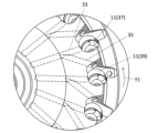
- 5 is a plan view similar to FIG. 4, but showing the second flow path and the like in a see-through manner.
- FIG. 5 is an enlarged view of region VI shown in FIG. 4 .
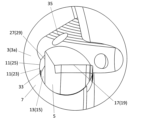
- FIG. 6 is an enlarged view of a portion of the cutting tool shown in FIG. 5 .
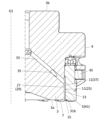
- FIG. 8 is a cross-sectional view of the cutting tool shown in FIG. 7 taken along line VIII. 8 is a cross-sectional view of the cutting tool shown in FIG. 7 taken along line IX. 2 is a perspective view of the cutting tool shown in FIG. 1 as seen from a different direction, with a part of the cutting tool being enlarged and showing a second flow passage and the like in a see-through manner;
- FIG. 13 is an enlarged view of region XIII shown in FIG. 12 .
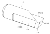
- FIG. 2 is a perspective view of a cutting insert in the cutting tool shown in FIG. 1 .
- FIG. 15 is a perspective view of the cutting insert shown in FIG. 14 as viewed from another direction.
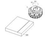
- FIG. 2 is a schematic diagram showing a step in a non-limiting method of manufacturing a one-sided machined product according to the present disclosure.
- FIG. 2 is a schematic diagram showing a step in a non-limiting method of manufacturing a one-sided machined product according to the present disclosure.
- FIG. 2 is a schematic diagram showing a step in a non-limiting method of manufacturing a one-sided machined product according to the present disclosure.
- a cutting tool 1 according to one aspect of the present disclosure will be described in detail with reference to the drawings.
- the cutting tool 1 may include any component member not shown in each of the drawings referred to.
- the dimensions of the components in each drawing do not faithfully represent the dimensions of the actual components and the dimensional ratios of each component.
- the cutting tool 1 may include a holder 3 and a cutting insert 5, as shown in a non-limiting example in Figures 1 to 15. This cutting tool 1 may be used for milling.
- the holder 3 may be a columnar body extending from a first end 3a to a second end 3b along the rotation axis O1, as shown in a non-limiting example in FIG. 1.
- the first end 3a is referred to as the "tip” and the second end 3b is referred to as the "rear end.”
- the holder 3 can rotate around the rotation axis O1.
- the arrow Y1 in FIG. 1 may indicate the direction of rotation of the rotation axis O1, or may indicate the direction of rotation of the holder 3 around the rotation axis O1.
- the holder 3 may be a cylindrical body. Note that the cylindrical body may be generally cylindrical, and does not have to be cylindrical in the strict sense.
- the holder 3 is not limited to a specific size.
- the length of the holder 3 in the direction along the rotation axis O1 may be set to approximately 30 to 80 mm.
- the width (diameter) of the holder 3 in the direction perpendicular to the rotation axis O1 may be set to approximately 20 to 400 mm.
- the cutting insert 5 may simply be called the insert 5.
- the insert 5 can be used to cut the workpiece in a cutting process.
- the holder 3 may have an end face 7 located on the side of the first end 3a and an outer peripheral surface 9, as shown in a non-limiting example in FIG. 2.
- the holder 3 may also have a pocket 11.
- the pocket 11 may open to the end face 7 and the outer peripheral surface 9.
- the insert 5 can be attached to the pocket 11.
- the number of pockets 11 may be the same as the number of inserts 5. When there are multiple pockets 11, the multiple pockets 11 may be positioned at equal intervals around the rotation axis O1, or may be positioned at unequal intervals.
- the insert 5 may be located in the pocket 11.
- a first flow passage 13 through which the coolant flows may be located between the holder 3 and the insert 5.
- the cutting tool 1 may be provided with a first flow passage 13 located between the holder 3 and the insert 5 and through which the coolant flows.
- the first flow passage 13 may have an opening 15 that opens on the side of the first end 3a.
- the opening 15 can function as an outlet for the coolant to flow out.
- the coolant flowing through the first flow passage 13 can reduce the risk of chips penetrating further inward than the insert 5. Therefore, the cutting tool 1 can reduce the risk of the surface of the workpiece being damaged by chips generated during cutting.
- the inner side may mean the side closer to the rotation axis O1.
- the opening 15 may open to the end face 7 located on the side of the first end 3a of the holder 3. In other words, the opening 15 may be located on the end face 7. In this case, it is easier to reduce the risk of chips penetrating further inward than the insert 5.
- the first flow passage 13 may extend along the rotation axis O1, as shown in a non-limiting example in FIG. 8. In this case, it is easier to supply the coolant to the surface of the workpiece.
- the insert 5 may be a columnar body, as shown in a non-limiting example in FIG. 14 and FIG. 15.
- the insert 5 may also have a cutting edge 17.
- the cutting tool 1 can perform cutting by bringing the cutting edge 17 of the insert 5 into contact with the workpiece.
- the insert 5 may be positioned in the pocket 11 such that at least a portion of the cutting edge 17 protrudes from the holder 3, as in the non-limiting example shown in FIG. 2.
- the cutting edge 17 may have a first cutting edge 19 located on the first end 3a side and a second cutting edge 21 located on the outer periphery side.
- the outer periphery side may mean the side away from the rotation axis O1.
- the opening 15 in the first flow passage 13 may be located closer to the rotation axis O1 than the insert 5, as in the non-limiting example shown in Figures 6 and 10. More specifically, the opening 15 may be located closer to the rotation axis O1 than the cutting edge 17 of the insert 5. In this case, it is easier to reduce the risk of chips penetrating the inner periphery of the insert 5.
- the opening 15 when viewed from the front from the first end 3a, the opening 15 may include an end 23 on the side of the rotation axis O1 in the pocket 11.
- the end 23 may be the portion of the pocket 11 closest to the rotation axis O1.
- the pocket 11 When viewed from the front from the first end 3a side, the pocket 11 may have a concave first portion 25 including the end portion 23 on the side of the rotation axis O1.
- the first portion 25 may extend along the rotation axis O1, as in a non-limiting example shown in FIG. 8.
- the first portion 25 may function as a portion that constitutes the first flow path 13.
- the coolant is more likely to flow stably through the first flow path 13.
- the first portion 25 may have a concave curved shape.
- the first flow passage 13 may be located between the holder 3 and a side surface 27 of the insert 5 facing the holder 3, as shown in a non-limiting example in FIG. 6.
- the side surface 27 may include a recess 29, as shown in a non-limiting example in FIG. 15.
- the recess 29 may extend along the rotation axis O1, as shown in a non-limiting example in FIG. 8.
- the recess 29 can function as a part that constitutes the first flow path 13. When the side surface 27 has the recess 29, the coolant can flow stably through the first flow path 13.
- the recess 29 may also have a flat surface area 31a that faces the holder 3 (see FIG. 15).
- the recess 29 may have an inclined surface 31b located on the side of the first end 3a (see Figures 14 and 15).
- the inclined surface 31b may be inclined so as to move away from the rotation axis O1 as it moves away from the second end 3b, as in a non-limiting example shown in Figure 8.
- a part of the inclined surface 31b may be located closer to the second end 3b than the end face 7. In these cases, the inclined surface 31b starting from the second end 3b side than the end face 7 makes it easier for the coolant to flow to the cutting edge 17.
- the inclined surface 31b may be located closer to the first end 3a than the region 31a.
- the inclined surface 31b may be inclined with respect to the region 31a.
- the inclined surface 31b may be connected to the region 31a.
- the holder 3 may have a second flow path 33 through which the coolant flows, as in a non-limiting example shown in FIG. 5.
- the second flow path 33 may extend from the second end 3b side toward the pocket 11, as in a non-limiting example shown in FIG. 8.
- the second flow path 33 may also open into the pocket 11.
- the second flow path 33 may be connected to the first flow path 13. In these cases, it is possible to appropriately supply coolant with a simple configuration.
- the second flow passage 33 may be inclined so as to approach the first end 3a as it approaches the outer peripheral surface 9, as shown in a non-limiting example in FIG. 8. In this case, the connection with the first flow passage 13 becomes smooth, making it possible to supply coolant with less pressure loss.
- the second flow path 33 may be located inside the holder 3.
- the second flow path 33 may also be linear.
- the second flow path 33 may be, for example, circular, elliptical, or polygonal in a cross section perpendicular to the direction in which the coolant flows.
- the inner diameter of the second flow path 33 may be set to, for example, about 0.5 to 5 mm.
- the second flow passage 33 may also open on the side of the rotation axis O1 of the holder 3, as in a non-limiting example shown in FIG. 8. This opening may function as an inlet for allowing coolant to flow into the inside of the second flow passage 33.
- the position of this opening is not particularly limited.
- the holder 3 may further include a third flow path 35 through which the coolant flows, as shown in a non-limiting example in FIG. 5.
- the third flow path 35 may extend from the second flow path 33.
- the third flow path 35 may branch off from the second flow path 33. In this case, a portion of the coolant flowing through the second flow path 33 may flow into the third flow path 35.
- the pocket 11 may include a first pocket 37 and a second pocket 39, as shown in a non-limiting example in FIG. 7 and FIG. 13.
- the second pocket 39 may be adjacent to the first pocket 37 behind the rotation direction Y1 of the rotation axis O1.
- the second flow path 33 may open into the first pocket 37.
- the third flow path 35 may open into the second pocket 39. In these cases, the third flow path 35 branches off from the second flow path 33, which is located relatively forward in the rotational direction Y1, making it easier to accurately supply coolant to the cutting edge 17.
- the opening in the second pocket 39 of the third flow path 35 can function as an outlet for allowing the coolant to flow out.
- the third flow path 35 may also be located inside the holder 3.
- the third flow path 35 may be linear.
- the third flow path 35 may be, for example, circular, elliptical, or polygonal in a cross section perpendicular to the direction in which the coolant flows.
- the inner diameter of the third flow path 35 may be set to, for example, about 0.5 to 5 mm.
- the insert 5 may include a first insert 41 and a second insert 43, as shown in a non-limiting example in FIG. 7.
- the first insert 41 may be located in the first pocket 37.
- the second insert 43 may be located in the second pocket 39.
- the second flow passage 33 may extend toward the side surface 27 of the first insert 41 that faces the holder 3, as shown in a non-limiting example in FIG. 8.
- the third flow passage 35 may extend toward the cutting edge 17 of the second insert 43, as shown in a non-limiting example in FIG. 9.
- the cutting tool 1 may include a fixing member 45, as shown in a non-limiting example in FIG. 1.
- the fixing member 45 may be a member for fixing the insert 5 to the holder 3.
- the number of fixing members 45 may be the same as the number of inserts 5.
- the fixing member 45 may be a screw, as shown in a non-limiting example in FIG. 1. Note that the fixing member 45 is not limited to a screw.
- the material of the holder 3 may be, for example, an aluminum alloy, steel, or cast iron. If the material of the holder 3 is steel, the holder 3 has high toughness.
- Materials for the insert 5 may include, for example, cemented carbide, cermet, ceramics, PCD (polycrystalline diamond), and cBN (cubic boron nitride).
- Cemented carbide compositions may include, for example, WC-Co, WC-TiC-Co, and WC-TiC-TaC-Co, where WC, TiC, and TaC may be hard particles, and Co may be a binder phase.
- the cermet may be a sintered composite material in which a ceramic component is combined with a metal.
- a cermet is a titanium compound whose main component is titanium carbide (TiC) or titanium nitride (TiN). It goes without saying that the material of the insert 5 is not limited to the above composition.
- the insert 5 may be made of only one member, or may be made of multiple members.
- the member where the cutting edge 17 is located may be made of a material with a relatively high hardness, such as PCD and cBN.
- the member where the cutting edge 17 is not located may be made of, for example, cemented carbide, cermet, ceramics, etc.
- the surface of the insert 5 may be coated with a coating using a chemical vapor deposition (CVD) method or a physical vapor deposition ( PVD ) method.
- the composition of the coating may include, for example, titanium carbide (TiC), titanium nitride (TiN), titanium carbonitride (TiCN), and alumina ( Al2O3 ).
- Coolants may include, for example, water-insoluble oils and water-soluble oils.
- Water-insoluble oils may include, for example, cutting oils such as oil-based, inactive extreme pressure, and active extreme pressure.
- Water-soluble oils may include, for example, cutting oils such as emulsions, solubles, and solutions.
- Coolants are not limited to liquids, and may be gases such as inert gases. Coolants may also be referred to as cooling fluids. Coolants may be appropriately selected and used depending on the material of the workpiece.
- the machined product 101 may be produced by cutting a workpiece 103.
- a manufacturing method of the machined product 101 may include the following steps. That is, (1) rotating a cutting tool 1 as typified by the non-limiting embodiment described above; (2) contacting the rotating cutting tool 1 with the workpiece 103; (3) a step of separating the cutting tool 1 from the workpiece 103; may also be provided.
- the cutting tool 1 may be rotated around the rotation axis O1 and brought relatively close to the workpiece 103.
- the cutting edge 17 of the insert 5 in the cutting tool 1 may be brought into contact with the workpiece 103 to cut the workpiece 103.
- the cutting tool 1 may be moved in a direction relatively away from the workpiece 103.
- step (1) the workpiece 103 may be brought closer to the cutting tool 1. Also, in step (3), the workpiece 103 may be moved away from the cutting tool 1. If cutting is to be continued, the cutting tool 1 may be kept rotating and the step of bringing the cutting tool 1 into contact with different locations of the workpiece 103 may be repeated.
- Examples of the material of the workpiece 103 include aluminum alloys, carbon steel, alloy steel, stainless steel, cast iron, and non-ferrous metals.
- the side surface 27 of the insert 5 facing the holder 3 has a recess 29, but instead, the holder 3 may have a recess 29.
- the portion of the holder 3 facing the insert 5 may have a recess 29 that extends along the rotation axis O1.
- the cutting tool 1 and the method for manufacturing the machined product 101 may be configured as follows.
- a cutting tool includes a cylindrical holder extending from a first end to a second end along a rotation axis, and one or more cutting inserts, the holder having one or more pockets opening to an end face and an outer peripheral face located on the side of the first end, the cutting insert being located in the pocket, and a first flow path through which a coolant flows being located between the holder and the cutting insert, the first flow path having an opening opening to the side of the first end.
- the first flow passage may extend along the rotation axis.
- the opening may be located closer to the rotation shaft than the cutting insert.
- the opening when viewed from the front from the first end side, the opening may include an end of the pocket on the rotation shaft side.
- the first flow path may be located between the holder and a side surface of the cutting insert facing the holder, and the side surface may have a recess extending along the rotation axis.
- the holder may have a second flow path extending from the second end side toward the pocket and through which coolant flows, the second flow path opening into the pocket and connected to the first flow path.
- the second flow passage may be inclined so as to approach the first end as it approaches the outer circumferential surface.
- the holder may further include a third flow path extending from the second flow path through which coolant flows, and the pocket may include a first pocket and a second pocket adjacent to the first pocket rearward in the rotational direction of the rotating shaft, and the second flow path may open to the first pocket and the third flow path may open to the second pocket.
- a method for manufacturing a machined product can include the steps of rotating a cutting tool selected from any one of (1) to (8) above, bringing the rotating cutting tool into contact with a workpiece, and removing the cutting tool from the workpiece.
- Cutting tool 3 Holder 3a: First end 3b: Second end 5: Cutting insert Reference Signs List 7: End face 9: Outer circumferential face 11: Pocket 13: First flow passage 15: Opening 17: Cutting edge 19: First cutting edge 21: Second cutting edge 23: End 25: First portion 27: Side face 29: Recess 31a: Area 31b: Inclined face 33: Second flow passage 35: Third flow passage 37: First pocket 39: Second pocket 41: First cutting insert (first insert) 43...Second cutting insert (second insert) 45: Fixed member 101: Cut workpiece 103: Workpiece O1: Rotation axis Y1: Rotation direction
Landscapes
- Engineering & Computer Science (AREA)
- Mechanical Engineering (AREA)
- Cutting Tools, Boring Holders, And Turrets (AREA)
Priority Applications (1)
| Application Number | Priority Date | Filing Date | Title |
|---|---|---|---|
| JP2025508163A JPWO2024195284A1 (https=) | 2023-03-20 | 2024-01-25 |
Applications Claiming Priority (2)
| Application Number | Priority Date | Filing Date | Title |
|---|---|---|---|
| JP2023043965 | 2023-03-20 | ||
| JP2023-043965 | 2023-03-20 |
Publications (1)
| Publication Number | Publication Date |
|---|---|
| WO2024195284A1 true WO2024195284A1 (ja) | 2024-09-26 |
Family
ID=92841189
Family Applications (1)
| Application Number | Title | Priority Date | Filing Date |
|---|---|---|---|
| PCT/JP2024/002142 Ceased WO2024195284A1 (ja) | 2023-03-20 | 2024-01-25 | 切削工具及び切削加工物の製造方法 |
Country Status (2)
| Country | Link |
|---|---|
| JP (1) | JPWO2024195284A1 (https=) |
| WO (1) | WO2024195284A1 (https=) |
Citations (9)
| Publication number | Priority date | Publication date | Assignee | Title |
|---|---|---|---|---|
| JPH0717401U (ja) * | 1993-09-06 | 1995-03-28 | 三菱マテリアル株式会社 | 切削工具 |
| JPH0839387A (ja) * | 1994-07-29 | 1996-02-13 | Mitsubishi Materials Corp | スローアウェイチップおよびこれを用いたフライスカッタ |
| JP2000005924A (ja) * | 1998-06-18 | 2000-01-11 | Mitsubishi Materials Corp | 正面フライス |
| JP2003053621A (ja) * | 2001-06-28 | 2003-02-26 | Camozzi Holding Spa | 流体冷却された硬質材料のインサートを有する高速度回転ツール |
| JP2014046446A (ja) * | 2012-09-04 | 2014-03-17 | Ngk Spark Plug Co Ltd | 切削工具用ホルダ及び切削工具 |
| CN103737091A (zh) * | 2013-12-30 | 2014-04-23 | 株洲钻石切削刀具股份有限公司 | 具有冷却结构的切削刀具 |
| WO2016121870A1 (ja) * | 2015-01-29 | 2016-08-04 | 京セラ株式会社 | 切削工具及び切削加工物の製造方法 |
| JP2017047491A (ja) * | 2015-08-31 | 2017-03-09 | 三菱マテリアル株式会社 | 切削インサート |
| JP2018534158A (ja) * | 2015-10-09 | 2018-11-22 | サンドビック インテレクチュアル プロパティー アクティエボラーグ | 溝穴フライス加工ディスク、溝穴フライス加工ディスクを含む溝穴フライス工具、および溝穴フライス加工ディスク用のディスク |
-
2024
- 2024-01-25 JP JP2025508163A patent/JPWO2024195284A1/ja active Pending
- 2024-01-25 WO PCT/JP2024/002142 patent/WO2024195284A1/ja not_active Ceased
Patent Citations (9)
| Publication number | Priority date | Publication date | Assignee | Title |
|---|---|---|---|---|
| JPH0717401U (ja) * | 1993-09-06 | 1995-03-28 | 三菱マテリアル株式会社 | 切削工具 |
| JPH0839387A (ja) * | 1994-07-29 | 1996-02-13 | Mitsubishi Materials Corp | スローアウェイチップおよびこれを用いたフライスカッタ |
| JP2000005924A (ja) * | 1998-06-18 | 2000-01-11 | Mitsubishi Materials Corp | 正面フライス |
| JP2003053621A (ja) * | 2001-06-28 | 2003-02-26 | Camozzi Holding Spa | 流体冷却された硬質材料のインサートを有する高速度回転ツール |
| JP2014046446A (ja) * | 2012-09-04 | 2014-03-17 | Ngk Spark Plug Co Ltd | 切削工具用ホルダ及び切削工具 |
| CN103737091A (zh) * | 2013-12-30 | 2014-04-23 | 株洲钻石切削刀具股份有限公司 | 具有冷却结构的切削刀具 |
| WO2016121870A1 (ja) * | 2015-01-29 | 2016-08-04 | 京セラ株式会社 | 切削工具及び切削加工物の製造方法 |
| JP2017047491A (ja) * | 2015-08-31 | 2017-03-09 | 三菱マテリアル株式会社 | 切削インサート |
| JP2018534158A (ja) * | 2015-10-09 | 2018-11-22 | サンドビック インテレクチュアル プロパティー アクティエボラーグ | 溝穴フライス加工ディスク、溝穴フライス加工ディスクを含む溝穴フライス工具、および溝穴フライス加工ディスク用のディスク |
Also Published As
| Publication number | Publication date |
|---|---|
| JPWO2024195284A1 (https=) | 2024-09-26 |
Similar Documents
| Publication | Publication Date | Title |
|---|---|---|
| US10384275B2 (en) | Cutting tool and method for manufacturing the machined product | |
| JP7630641B2 (ja) | 切削インサート、切削工具、及び切削加工物の製造方法 | |
| CN115515740A (zh) | 钻头以及切削加工物的制造方法 | |
| US12220753B2 (en) | Rotary tool and method for manufacturing machined product | |
| CN111263676B (zh) | 切削刀具以及切削加工物的制造方法 | |
| JP6691549B2 (ja) | ドリル用ホルダ、ドリル及び切削加工物の製造方法 | |
| JP7023295B2 (ja) | ドリル及び切削加工物の製造方法 | |
| JP7103933B2 (ja) | 切削インサート、回転工具及び切削加工物の製造方法 | |
| US11358230B2 (en) | End mill and method for manufacturing machined product | |
| JP7344321B2 (ja) | 回転工具及び切削加工物の製造方法 | |
| JP7216744B2 (ja) | ホルダ、切削工具及び切削加工物の製造方法 | |
| WO2024195284A1 (ja) | 切削工具及び切削加工物の製造方法 | |
| JP7465980B2 (ja) | 回転工具及び切削加工物の製造方法 | |
| WO2024195286A1 (ja) | ホルダ、切削工具及び切削加工物の製造方法 | |
| WO2023228741A1 (ja) | 切削工具及び切削加工物の製造方法 | |
| JP7045460B2 (ja) | 切削工具及び切削加工物の製造方法 | |
| JP7700062B2 (ja) | 回転工具及び切削加工物の製造方法 | |
| JP7746403B2 (ja) | ホルダ、切削工具及び切削加工物の製造方法 | |
| JP6825854B2 (ja) | 切削工具及び切削加工物の製造方法 | |
| JP7279163B2 (ja) | 回転工具及び切削加工物の製造方法 | |
| JP7770537B2 (ja) | 回転工具及び切削加工物の製造方法 | |
| WO2025074852A1 (ja) | 切削インサート、切削工具、および切削加工物の製造方法 | |
| JP2025030995A (ja) | 回転工具及び切削加工物の製造方法 | |
| WO2024202390A1 (ja) | 切削工具及び切削加工物の製造方法 | |
| WO2026088668A1 (ja) | ドリル、及び切削加工物の製造方法 |
Legal Events
| Date | Code | Title | Description |
|---|---|---|---|
| 121 | Ep: the epo has been informed by wipo that ep was designated in this application |
Ref document number: 24774430 Country of ref document: EP Kind code of ref document: A1 |
|
| ENP | Entry into the national phase |
Ref document number: 2025508163 Country of ref document: JP Kind code of ref document: A |
|
| WWE | Wipo information: entry into national phase |
Ref document number: 2025508163 Country of ref document: JP |
|
| NENP | Non-entry into the national phase |
Ref country code: DE |
|
| 122 | Ep: pct application non-entry in european phase |
Ref document number: 24774430 Country of ref document: EP Kind code of ref document: A1 |