WO2024195283A1 - 生体音センサ - Google Patents
生体音センサ Download PDFInfo
- Publication number
- WO2024195283A1 WO2024195283A1 PCT/JP2024/002120 JP2024002120W WO2024195283A1 WO 2024195283 A1 WO2024195283 A1 WO 2024195283A1 JP 2024002120 W JP2024002120 W JP 2024002120W WO 2024195283 A1 WO2024195283 A1 WO 2024195283A1
- Authority
- WO
- WIPO (PCT)
- Prior art keywords
- housing
- diaphragm
- contact surface
- sound sensor
- plate
- Prior art date
- Legal status (The legal status is an assumption and is not a legal conclusion. Google has not performed a legal analysis and makes no representation as to the accuracy of the status listed.)
- Ceased
Links
Images




Classifications
-
- A—HUMAN NECESSITIES
- A61—MEDICAL OR VETERINARY SCIENCE; HYGIENE
- A61B—DIAGNOSIS; SURGERY; IDENTIFICATION
- A61B7/00—Instruments for auscultation
- A61B7/02—Stethoscopes
- A61B7/04—Electric stethoscopes
-
- H—ELECTRICITY
- H04—ELECTRIC COMMUNICATION TECHNIQUE
- H04R—LOUDSPEAKERS, MICROPHONES, GRAMOPHONE PICK-UPS OR LIKE ACOUSTIC ELECTROMECHANICAL TRANSDUCERS; ELECTRIC HEARING AIDS; PUBLIC ADDRESS SYSTEMS
- H04R17/00—Piezoelectric transducers; Electrostrictive transducers
- H04R17/02—Microphones
-
- A—HUMAN NECESSITIES
- A61—MEDICAL OR VETERINARY SCIENCE; HYGIENE
- A61B—DIAGNOSIS; SURGERY; IDENTIFICATION
- A61B2562/00—Details of sensors; Constructional details of sensor housings or probes; Accessories for sensors
- A61B2562/02—Details of sensors specially adapted for in-vivo measurements
- A61B2562/0204—Acoustic sensors
-
- A—HUMAN NECESSITIES
- A61—MEDICAL OR VETERINARY SCIENCE; HYGIENE
- A61B—DIAGNOSIS; SURGERY; IDENTIFICATION
- A61B2562/00—Details of sensors; Constructional details of sensor housings or probes; Accessories for sensors
- A61B2562/16—Details of sensor housings or probes; Details of structural supports for sensors
Definitions
- This disclosure relates to a biological sound sensor.
- Patent Document 1 discloses, as an example of a biological sound sensor, a body-conducted sound sensor that includes a microphone element, an elastic polymer material having a sound wave input surface that contacts the surface of the human body to input sound waves, and a container that houses the microphone element and to which the elastic polymer material is attached with the sound wave input surface exposed. Sound waves are transmitted from the sound wave input surface to the microphone element via the elastic polymer material.
- the container has open ends around the sound wave input surface, and when the sound wave input surface is in contact with the surface of the human body, the open ends also come into contact with the surface of the human body, which may generate noise. If the noise is transmitted to the microphone element, the body sound sensor may not be able to detect body sounds with high accuracy.
- the present disclosure has been made in consideration of the above, and aims to suppress noise generation in a body sound sensor and accurately detect body sounds.
- the biological sound sensor disclosed herein comprises a housing, a plate-shaped diaphragm having a first plate surface and a second plate surface located on opposite sides of each other and capable of vibrating along the thickness direction, a piezoelectric element disposed on the first plate surface and detecting the vibration of the diaphragm, and a soft member having a contact surface that contacts the living body and a non-contact surface that is separated from the living body when the contact surface is in contact with the living body, the soft member being softer than the diaphragm, the housing holding one of the first plate surface and the non-contact surface, the second plate surface being attached to the non-contact surface from the center to the periphery of the second plate surface.
- the body sound sensor disclosed herein can suppress noise generation and accurately detect body sounds.
- FIG. 1 is a cross-sectional view showing the configuration of a body sound sensor according to a first embodiment of the present disclosure.
- FIG. 2 is a cross-sectional view showing a configuration of a body sound sensor according to a modified example of the first embodiment of the present disclosure.
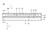
- FIG. 3 is a cross-sectional view showing the configuration of a body sound sensor according to the second embodiment of the present disclosure.
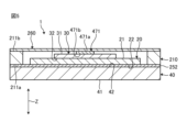
- FIG. 4 is a cross-sectional view showing a configuration of a body sound sensor according to a first modified example of the second embodiment of the present disclosure.
- FIG. 5 is a cross-sectional view showing the configuration of a body sound sensor according to a second modified example of the second embodiment of the present disclosure.
- FIG. 1 is a cross-sectional view showing the configuration of a body sound sensor according to a first embodiment of the present disclosure.
- FIG. 2 is a cross-sectional view showing a configuration of a body sound sensor according to a modified example of the first embodiment of the present disclosure.
- FIG. 3
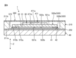
- FIG. 6 is a cross-sectional view showing the configuration of a body sound sensor according to a third modified example of the second embodiment of the present disclosure.
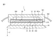
- FIG. 7 is a cross-sectional view showing the configuration of a body sound sensor according to the third embodiment of the present disclosure.
- FIG. 8 is a cross-sectional view showing the configuration of a body sound sensor according to another modified example of the first embodiment of the present disclosure.
- FIG. 1 is a cross-sectional view showing the configuration of a biological sound sensor 1 according to a first embodiment of the present disclosure.
- the Z direction shown in the drawing is the thickness direction of a diaphragm 20, which will be described later.
- plane view means viewing the biological sound sensor 1 along the Z direction.
- Fig. 1 shows a state in which a soft member 40, which will be described later, is in contact with an outer surface B1 of a living body B.
- the biological sound sensor 1 comes into contact with the outer surface B1 of a biological body B (e.g., a human body) and detects biological sounds (e.g., heart sounds).
- the biological sound sensor 1 is cylindrical with flat surfaces on both sides in the Z direction. It goes without saying that the biological sound sensor 1 is not limited to a cylindrical shape, and may be, for example, rectangular.
- the biological sound sensor 1 comprises a housing 10, a vibration plate 20, a piezoelectric element 30, and a soft member 40.
- the housing 10 is box-shaped and has an opening at one end in the Z direction.
- the opening end 11 of the housing 10 is annular in plan view.
- the material of the housing 10 is, for example, a thermoplastic resin.
- the diaphragm 20 is in the shape of a plate having a first plate surface 21 and a second plate surface 22 located on opposite sides of each other.
- the diaphragm 20 is, for example, in the shape of a disk.
- the first plate surface 21 and the second plate surface 22 are planar.
- the diaphragm 20 can vibrate along the Z direction (thickness direction).
- the diaphragm 20 is electrically conductive.
- the material of the diaphragm 20 is a metal (for example, copper and nickel).
- the diaphragm 20 is held by the housing 10 with the first plate surface 21 attached to the opening edge 11 of the housing 10.
- the housing 10 holds the first plate surface 21.
- the peripheral edge of the first plate surface 21 is held by the opening edge 11.
- the diaphragm 20 covers the opening of the housing 10.
- the first plate surface 21 is held by the opening edge 11 via an adhesive layer (not shown).
- the adhesive layer may be formed by a sticky tape, or may be formed by hardening an adhesive.
- the piezoelectric element 30 is housed in the housing 10.
- the piezoelectric element 30 detects the vibration of the diaphragm 20.
- the piezoelectric element 30 is a piezo element.
- the piezoelectric element 30 is, for example, a PZT-based piezoelectric ceramic made of lead zirconate titanate.
- the piezoelectric element 30 is in the form of a film having a first electrode surface 31 and a second electrode surface 32 located on opposite sides.
- the piezoelectric element 30 is disposed on the first plate surface 21 of the diaphragm 20 with the second electrode surface 32 electrically connected to the first plate surface 21.
- the second electrode surface 32 is disposed on the first plate surface 21, for example, via a conductive adhesive layer (not shown) having electrical conductivity.
- the conductive adhesive layer is, for example, a hardened adhesive containing a conductive filler (e.g., silver particles).
- the piezoelectric element 30 deforms in response to the vibration of the diaphragm 20, and a voltage is generated between the first electrode surface 31 and the second electrode surface 32.
- the soft member 40 transmits the vibrations of the living organism B to the diaphragm 20.
- the soft member 40 has a contact surface 41 and a non-contact surface 42.
- the contact surface 41 is the surface that contacts the living organism B.
- the non-contact surface 42 is the surface that is separated from the living organism B when the contact surface 41 is in contact with the living organism B. When the contact surface 41 is separated from the living organism B, the contact surface 41 and the non-contact surface 42 are planar.
- the soft member 40 is plate-shaped, and the contact surface 41 and the non-contact surface 42 are located on opposite sides of each other.
- the soft member 40 is, for example, disk-shaped.
- the soft member 40 and the vibration plate 20 are plate-shaped, and the piezoelectric element 30 is film-shaped. Therefore, the thickness of the biological sound sensor 1 can be reduced.
- the soft member 40 has flexibility.
- the soft member 40 is softer than the vibration plate 20.
- the soft member 40 has a hardness that allows the contact surface 41 to deform along the outer surface B1 of the living body B when the contact surface 41 is in contact with the living body B.
- the Shore A hardness of the soft member 40 is 50 or less.
- the Asker C hardness of the soft member 40 is approximately 15. It goes without saying that the hardness of the soft member 40 is not limited to the above value.
- the soft member 40 has elasticity.
- the soft member 40 has an acoustic impedance between the acoustic impedance of the skin of the living body B and the acoustic impedance of the diaphragm 20. This allows the soft member 40 to transmit the living body sound appropriately.
- the material of the soft member 40 is a polymer material (such as silicone and urethane rubber).
- the second plate surface 22 of the vibration plate 20 is attached to the non-contact surface 42 from the center to the periphery of the second plate surface 22.
- the second plate surface 22 is attached to the non-contact surface 42 up to every corner of the second plate surface 22.
- the non-contact surface 42 and the second plate surface 22 are attached via a first adhesive member 51.
- the thickness of the first adhesive member 51 is constant. No member other than the first adhesive member 51 is interposed between the non-contact surface 42 and the second plate surface 22. This prevents the non-contact surface 42 and the contact surface 41 from having convex and concave shapes along the thickness direction.
- the first adhesive member 51 may be formed of an adhesive tape, or may be formed by hardening an adhesive.
- the entire housing 10 is located on the opposite side of the contact surface 41 across the first plate surface 21. Furthermore, when the soft member 40 is viewed from the contact surface 41 side along the thickness direction (Z direction) of the vibration plate 20, the entire housing 10 is hidden by the soft member 40. This prevents the housing 10 from coming into contact with the living body B when the contact surface 41 is in contact with the living body B.
- the biological sound sensor 1 further includes a first electric wire L1 and a second electric wire L2.
- a first end of the first electric wire L1 is electrically connected to a first electrode surface 31 of the piezoelectric element 30.
- a first end of the second electric wire L2 is electrically connected to a first plate surface 21 of the vibration plate 20.
- the vibration plate 20 has electrical conductivity, and the first plate surface 21 and the second electrode surface 32 are electrically connected. Therefore, the first end of the second electric wire L2 is electrically connected to the second electrode surface 32 via the vibration plate 20.
- the second ends of the first electric wire L1 and the second electric wire L2 are located outside the housing 10 and are electrically connected to, for example, a measuring instrument (not shown).
- the body sound sensor 1 detects body sound.
- vibrations of the outer surface B1 of the living body B are transmitted from the contact surface 41 to the soft member 40.
- the contact surface 41 is deformed along the outer surface B1 of the living body B and is in close contact with the outer surface B1 of the living body B.
- the generation of convex and concave shapes along the thickness direction of the contact surface 41 is suppressed. Therefore, it is possible to suppress the generation of relatively large stresses locally in the soft member 40 due to contact between the contact surface 41 and the outer surface B1 of the living body B.
- noise noise due to friction between the contact surface 41 and the outer surface B1 of the living body B. Therefore, the soft member 40 can transmit biological vibrations with high precision.
- the biological vibrations are transmitted to the diaphragm 20 via the soft member 40.
- the soft member 40 vibrates due to the biological vibrations, and the diaphragm 20 vibrates in response to the vibration of the soft member 40.
- the piezoelectric element 30 vibrates in response to the vibration of the diaphragm 20.
- a voltage corresponding to the vibration of the piezoelectric element 30 is generated between the first electrode surface 31 and the second electrode surface 32.
- the waveform of the voltage generated in the piezoelectric element 30 corresponds to the waveform of the biological sound.
- the biological sound sensor 1 detects the voltage generated in the piezoelectric element 30 as biological sound.
- the voltage generated in the piezoelectric element 30 is output to a measuring instrument via the first electric wire L1 and the second electric wire L2.
- the living body sound sensor 1 can detect living body sounds with high accuracy.
- FIG. 2 is a cross-sectional view showing the configuration of a biological sound sensor 1 according to a modified example of the first embodiment of the present disclosure. Compared to the biological sound sensor 1 of the first embodiment described above, the biological sound sensor 1 according to this modified example further includes an electric circuit 160.
- the electric circuit 160 has a plate shape and is housed in the housing 10.
- the second ends of the first electric wire L1 and the second electric wire L2 are electrically connected to the electric circuit 160.
- the first electrode surface 31 is electrically connected to the electric circuit 160 via the first electric wire L1
- the second electrode surface 32 is electrically connected to the electric circuit 160 via the vibration plate 20 and the second electric wire L2.
- the voltage generated in the piezoelectric element 30 is output to the electric circuit 160.
- the electric circuit 160 includes an amplifier 161, a filter section 162, and an output section 163.
- the amplifier 161 amplifies the voltage output from the piezoelectric element 30.
- the filter section 162 removes electrical noise generated in the electric circuit 160.
- the output section 163 outputs the voltage amplified by the amplifier 161 (voltage corresponding to the body sound) to a measuring instrument.
- the output section 163 is, for example, a connector that electrically connects to the measuring instrument via an electric wire (not shown).
- the output section 163 may be a transmitter that wirelessly transmits a signal including information corresponding to the voltage amplified by the amplifier 161 to the measuring instrument.
- the first electric wire L1 and the second electric wire L2 of this modified example are stored in the housing 10, and the length of the first electric wire L1 and the second electric wire L2 of this modified example is shorter than the length of the first electric wire L1 and the second electric wire L2 of the first embodiment described above. This makes it possible to prevent electrical noise from entering the first electric wire L1 and the second electric wire L2 from the outside. Therefore, the biological sound sensor 1 can output biological sound with high accuracy.
- the piezoelectric element 30 may also include a piezoelectric body (not shown) having a piezoelectric effect, and a first electrode (not shown) and a second electrode (not shown) that sandwich the piezoelectric body in the Z direction.
- the piezoelectric body deforms in response to the vibration of the vibration plate 20, generating a voltage between the first electrode and the second electrode.
- the first electrode has a first electrode surface 31, and the second electrode has a second electrode surface 32. In this case, the vibration plate 20 does not need to have electrical conductivity, and the first end of the second electric wire L2 is electrically connected to the second electrode.
- the biological sound sensor 1 according to the second embodiment of the present disclosure will be described, focusing mainly on the differences from the biological sound sensor 1 according to the modified example of the above-described first embodiment.
- FIG. 3 is a cross-sectional view showing the configuration of a biological sound sensor 1 according to a second embodiment of the present disclosure. Compared to the biological sound sensor 1 of the first embodiment described above, the biological sound sensor 1 according to the second embodiment does not include the first electric wire L1 and the second electric wire L2.
- the housing 210 in this second embodiment is cylindrical with openings on both sides in the Z direction.
- the open end of the housing 210 on the soft member 40 side is referred to as the first open end 211a
- the open end opposite the first open end 211a is referred to as the second open end 211b.
- the housing 210 is also electrically conductive.
- the material of the housing 210 may be, for example, a metal, or a thermoplastic resin containing a conductive filler (for example, fine particles of carbon (so-called carbon black)).
- the electric circuit 260 is disk-shaped, and the second opening end 211b holds the peripheral edge of the electric circuit 260. As a result, the electric circuit 260 covers the opening of the housing 210 on the second opening end 211b side. The second opening end 211b also holds the electric circuit 260 via a conductive adhesive layer (not shown). As a result, the housing 210 and the electric circuit 260 are electrically connected.
- the piezoelectric element 30 and the diaphragm 20 are housed in a housing 210.
- the first electrode surface 31 and the electrical circuit 260 are electrically connected in contact with each other via a conductive adhesive layer (not shown).
- the soft member 40 is held by the housing 210 with the non-contact surface 42 attached to the first opening end 211a of the housing 210.
- the housing 210 holds the non-contact surface 42.
- the peripheral portion of the non-contact surface 42 is held by the first opening end 211a.
- the soft member 40 covers the opening on the first opening end 211a side of the housing 210.
- the second plate surface 22 of the diaphragm 20 and the first opening end 211a of the housing 210 are attached to the non-contact surface 42 via a second adhesive member 252 having electrical conductivity.
- the second adhesive member 252 may be, for example, a hardened adhesive containing a conductive filler (e.g., silver particles), or may be an adhesive tape containing a conductive filler.
- the entire housing 210 is located on the opposite side of the contact surface 41 with the non-contact surface 42 in between. This prevents noise from being generated by the housing 210 coming into contact with the living body B.
- the second plate surface 22 of the diaphragm 20 is attached to the non-contact surface 42 from the center to the periphery of the second plate surface 22 via the second adhesive member 252.
- the thickness of the second adhesive member 252 is constant. No member other than the second adhesive member 252 is interposed between the non-contact surface 42 and the second plate surface 22. This prevents the non-contact surface 42 and the contact surface 41 from having convex and concave shapes along the thickness direction, as in the first embodiment described above.
- the second adhesive member 252 is continuous from the second plate surface 22 of the vibration plate 20 to the second opening end 211b of the housing 210.
- the vibration plate 20 and the housing 210 are electrically connected via the second adhesive member 252. Therefore, the second electrode surface 32 of the piezoelectric element 30 is electrically connected to the electric circuit 260 via the vibration plate 20, the second adhesive member 252, and the housing 210. Therefore, the voltage generated in the piezoelectric element 30 is output to the electric circuit 260.
- the voltage generated by the piezoelectric element 30 is output to the electric circuit 260 without passing through an electric wire. Therefore, the thickness of the biological sound sensor 1 can be reduced.
- FIG. 4 is a cross-sectional view showing the configuration of a biological sound sensor 1 according to a first modified example of the second embodiment of the present disclosure.
- the soft member 340 has electrical conductivity.
- the material of the soft member 340 is, for example, a polymeric material containing a conductive filler.
- the biological sound sensor 1 includes two second adhesive members 352.
- one second adhesive member 352 will be referred to as the first second adhesive member 352a, and the other second adhesive member 352 will be referred to as the second second adhesive member 352b.
- the second plate surface 22 of the diaphragm 20 is attached to the non-contact surface 342 via the first second adhesive member 352a. No other member than the first second adhesive member 352a is interposed between the non-contact surface 342 and the second plate surface 22.
- the diaphragm 20 and the soft member 340 are electrically connected via the first second adhesive member 352a.
- the first opening end 211a of the housing 210 is attached to the non-contact surface 342 via a second adhesive member 352b.
- the second adhesive member 352b is annular in plan view and surrounds the first adhesive member 352a. This electrically connects the soft member 340 and the housing 210 via the second adhesive member 352b.
- the second electrode surface 32 of the piezoelectric element 30 is electrically connected to the electrical circuit 260 via the vibration plate 20, the first second adhesive member 352a, the soft member 340, the second second adhesive member 352b, and the housing 210.
- first second adhesive member 352a and the second second adhesive member 352b may be integral.
- FIG. 5 is a cross-sectional view showing the configuration of a biological sound sensor 1 according to a second modified example of the second embodiment of the present disclosure.
- the biological sound sensor 1 according to the second modified example further includes a first connecting member 471.
- the first connecting member 471 is housed in the housing 210.
- the first connecting member 471 is columnar in shape and has a first end face 471a and a second end face 471b, and is electrically conductive. The area of each of the first end face 471a and the second end face 471b is smaller than the area of the first electrode surface 31.
- the material of the first connecting member 471 is, for example, a thermoplastic resin containing a conductive filler.
- the first connecting member 471 connects the piezoelectric element 30 to the electric circuit 260 while electrically connecting the first electrode surface 31 to the electric circuit 260. Specifically, the first end surface 471a and the electric circuit 260 are electrically connected via a conductive adhesive layer (not shown). The second end surface 471b and the first electrode surface 31 are electrically connected via a conductive adhesive layer (not shown). The first connecting member 471 is disposed in the center of the piezoelectric element 30 in a plan view.
- the piezoelectric element 30 and the diaphragm 20 vibrate while being supported by the first connecting member 471. That is, the piezoelectric element 30 and the diaphragm 20 vibrate with the first connecting member 471 as the fulcrum. This increases the amplitude of the piezoelectric element 30 and the diaphragm 20 in response to the biological vibration.
- the first connecting member 471 amplifies the amplitude of the piezoelectric element 30 and the diaphragm 20. Therefore, the first connecting member 471 can improve the sensitivity of the biological sound sensor 1.
- FIG. 6 is a cross-sectional view showing the configuration of a biological sound sensor 1 according to a third modified example of the second embodiment of the present disclosure.
- the biological sound sensor 1 according to the third modified example includes two diaphragms 520 and further includes a second connecting member 572.
- one diaphragm 520 is referred to as a first diaphragm 520a
- the other diaphragm is referred to as a second diaphragm 520b.
- the first diaphragm 520a and the second diaphragm 520b may be different sizes or may be the same size.
- the piezoelectric element 30, the first diaphragm 520a, the second diaphragm 520b, the first connecting member 471, and the second connecting member 572 are housed in the housing 210.
- the first vibration plate 520a is plate-shaped with a first plate surface 521a and a second plate surface 522a located on opposite sides, has electrical conductivity, and can vibrate along the thickness direction.
- the second vibration plate 520b is plate-shaped with a first plate surface 521b and a second plate surface 522b located on opposite sides, has electrical conductivity, and can vibrate along the thickness direction.
- the first vibration plate 520a has a piezoelectric element 30 disposed on the first plate surface 521a, similar to the vibration plate 20 of the second modified example of the second embodiment described above. That is, the piezoelectric element 30 is disposed on the first plate surface 521a of the first vibration plate 520a with the second electrode surface 32 and the first plate surface 521a of the first vibration plate 520a being electrically connected, and detects the vibration of the first vibration plate 520a.
- the second connecting member 572 is electrically conductive and connects the first diaphragm 520a and the second diaphragm 520b in a state in which the second plate surface 522a of the first diaphragm 520a and the first plate surface 521b of the second diaphragm 520b are electrically connected.
- the material of the second connecting member 572 is, for example, a thermoplastic resin containing a conductive filler.
- the second connecting member 572 is annular and surrounds the first connecting member 471 when the second diaphragm 520b is viewed along the Z direction (thickness direction).
- the second connecting member 572 is sandwiched between the peripheral portion of the first diaphragm 520a and the peripheral portion of the second diaphragm 520b.
- the second connecting member 572 has a first end surface 572a and a second end surface 572b.
- the first end surface 572a and the second plate surface 522a of the first vibration plate 520a are electrically connected via a conductive adhesive layer (not shown).
- the second end surface 572b and the first plate surface 521b of the second vibration plate 520b are electrically connected via a conductive adhesive layer (not shown).
- the soft member 40 is softer than the first vibration plate 520a and the second vibration plate 520b.
- the soft member 40 transmits biological vibration to the second vibration plate 520b.
- the second plate surface 522b of the second vibration plate 520b is attached to the non-contact surface 42 of the soft member 40 from the center to the periphery of the second plate surface 522b via the second adhesive member 252, as in the second embodiment described above.
- No member other than the second adhesive member 252 is interposed between the non-contact surface 42 and the second plate surface 522b of the second vibration plate 520b. This prevents the non-contact surface 42 and the contact surface 41 from having convex and concave shapes along the thickness direction, as in the second embodiment described above.
- the first opening end 211a of the housing 210 is attached to the non-contact surface 42 via the second adhesive member 252, as in the second embodiment described above.
- the second electrode surface 32 is electrically connected to the electrical circuit 260 via the first diaphragm 520a, the second connecting member 572, the second diaphragm 520b, the second adhesive member 252, and the housing 210.
- the second connecting member 572 surrounds the first connecting member 471 when the second vibration plate 520b is viewed along the Z direction, so that the piezoelectric element 30 and the first vibration plate 520a vibrate with the first connecting member 471 and the second connecting member 572 as support.
- This increases the amplitude of the piezoelectric element 30 and the first vibration plate 520a in response to the biological vibration.
- the first connecting member 471 and the second connecting member 572 amplify the amplitude of the piezoelectric element 30 and the first vibration plate 520a. Therefore, the first connecting member 471 and the second connecting member 572 can improve the sensitivity of the biological sound sensor 1.
- the biological sound sensor 1 according to the third embodiment of the present disclosure will be described, focusing mainly on the differences from the biological sound sensor 1 according to the second embodiment (see FIG. 3 ).
- FIG. 7 is a cross-sectional view showing the configuration of a biological sound sensor 1 according to a third embodiment of the present disclosure.
- the biological sound sensor 1 of the third embodiment further includes a second housing 681 and an attachment 682.
- the housing 210 is attached to the second housing 681.
- the second housing 681 has a recess 681a into which the electrical circuit 260 and the housing 210 fit.
- the material of the second housing 681 is, for example, a thermoplastic resin.
- the entire second housing 681 is located on the opposite side of the contact surface 41 across the non-contact surface 42. This makes it possible to suppress noise that would be generated by the second housing 681 coming into contact with the living body B.
- the attachment 682 is a second housing 681 with the housing 210 attached, which is attached to the living body B with the contact surface 41 in contact with the outer surface B1 of the living body B.
- the attachment 682 is belt-shaped and is wrapped around the torso and arm of the living body B, for example. This allows the living body sound sensor 1 to be attached to the living body B and to continuously detect living body sounds. It also improves the adhesion between the contact surface 41 and the outer surface B1 of the living body B, and prevents the contact surface 41 from shifting from the outer surface B1 of the living body B.
- the second housing 681 may be attached to the housing 210 of the biological sound sensor 1 (see FIG. 1) according to the first embodiment. In this case, the entire second housing 681 is located on the opposite side of the contact surface 41 across the first plate surface 21.
- the electric circuit 160 may not include either the amplifier 161 or the filter section 162. Also, when the soft member 40 is viewed from the contact surface 41 side along the thickness direction of the diaphragm 20, a part of the housing 10, 210 may be exposed from the soft member 40.
- FIG. 8 is a cross-sectional view showing the configuration of a biological sound sensor 1 according to another modified example of the first embodiment of the present disclosure.
- the inside of the housing 10 of this modified example is filled with a filling material 790.
- the filling member 790 is softer than the soft member 40.
- the material of the filling member 790 is a polymer material (such as silicone and urethane rubber).
- the hardness of the filling member 790 changes the amplitude of the vibration plate 20 in response to the biological vibration.
- the sensitivity of the biological sound sensor 1 can be adjusted by the hardness of the filling member 790.
- the filling member 790 can suppress the impact acting on the piezoelectric element 30 and the vibration plate 20 when the biological sound sensor 1 is dropped, and prevent damage to the piezoelectric element 30 and the vibration plate 20.
- the filling member 790 can suppress noise that enters from the outside other than biological vibration.
- the filling member 790 may be filled inside the housing 210 of the biological sound sensor 1 of the second embodiment described above.
- the body sound sensor 1 of each of the above embodiments and each modified example as in the body sound sensor 1 of the first embodiment, when the contact surface 41 is in contact with the body B, the contact surface 41 is in close contact with the outer surface B1 of the body B, which can prevent relatively large stress from being generated locally in the soft member 40 and can prevent noise from being generated due to friction between the contact surface 41 and the outer surface B1 of the body B. Furthermore, in the body sound sensor 1 of each of the embodiments and each modified example, the housing 10, 210 and the second housing 681 are prevented from contacting the body B, which prevents noise from being generated due to the housing 10, 210 contacting the body B. Therefore, the body sound sensor 1 can detect body sound with high accuracy.
- a housing and a diaphragm having a plate shape with a first plate surface and a second plate surface located opposite to each other and capable of vibrating along a thickness direction; a piezoelectric element disposed on the first plate surface and detecting vibration of the diaphragm; a soft member having a contact surface that contacts the living body and a non-contact surface that is separated from the living body when the contact surface is in contact with the living body, the soft member being softer than the diaphragm; the housing holds one of the first plate surface and the non-contact surface, The second plate surface is attached to the non-contact surface from the center to the periphery of the second plate surface.
- Biological sound sensor
- the soft member has a plate shape having the contact surface and the non-contact surface on opposite sides.
- the entire housing is located on the opposite side of the contact surface with one of the first plate surface and the non-contact surface interposed therebetween;
- the biological sound sensor according to (1) or (2).
- the biological sound sensor according to any one of (1) to (3).
- the diaphragm is electrically conductive
- the piezoelectric element includes a first electrode surface and a second electrode surface electrically connected to the electric circuit
- the second electrode surface is disposed on the first plate surface and is electrically connected to the electric circuit via the diaphragm
- a biological sound sensor according to any one of (1) to (4).
- the piezoelectric element and the diaphragm are housed in the housing, the housing has electrical conductivity, is electrically connected to the electric circuit, and holds the non-contact surface; the second plate surface and the housing are attached to the non-contact surface via an adhesive member having electrical conductivity; the second electrode surface is electrically connected to the electric circuit via the diaphragm, the adhesive member, and the housing;
- the biological sound sensor according to (5).
- the soft member has electrical conductivity, the second electrode surface is electrically connected to the electric circuit via the vibration plate, the adhesive member, the soft member, and the housing;
- the biological sound sensor according to (7).
- the inside of the housing is filled with a filling material softer than the soft material.
- a biological sound sensor according to any one of (1) to (9).
- a second housing to which the housing is attached; and and a mounting body for mounting the second housing to which the housing is attached to the living body in a state in which the contact surface is in contact with an outer surface of the living body, the second housing is located on the opposite side of the contact surface with one of the first plate surface and the non-contact surface interposed therebetween,
- the biological sound sensor according to any one of (1) to (10).
- the second housing is located on the opposite side of the contact surface with one of the first plate surface and the non-contact surface interposed therebetween, The biological sound sensor according to (11).
- An electrically conductive housing an electric circuit held in the housing; a first diaphragm and a second diaphragm each having a plate shape with a first plate surface and a second plate surface located opposite to each other, having electrical conductivity, and capable of vibrating along a thickness direction; a piezoelectric element having a first electrode surface and a second electrode surface, the piezoelectric element being disposed on the first plate surface of the first diaphragm in a state in which the second electrode surface and the first plate surface of the first diaphragm are electrically connected to each other, the piezoelectric element detecting vibration of the first diaphragm; a columnar first connecting member having electrical conductivity and connecting the piezoelectric element and the electric circuit in a state in which the first electrode surface and the electric circuit are electrically connected; a ring-shaped second connecting member that has electrical conductivity, connects the first diaphragm and the second diaphragm in a state in which the second plate surface of the first diaphra
- Body sound sensor 10 Housing 20 Vibration plate 21 First plate surface 22 Second plate surface 30 Piezoelectric element 31 First electrode surface 32 Second electrode surface 40 Soft member 41 Contact surface 42 Non-contact surface 51 First adhesive member (adhesion parts) 160 Electric circuit 252 Second adhesive member (adhesive member) 471: First connecting member 471a: First end surface 471b: Second end surface (end surface of the first connecting member) 572 Second connecting member 681 Second housing 682 Mounting body 790 Filling member B Living body B1 Outer surface
Landscapes
- Acoustics & Sound (AREA)
- Physics & Mathematics (AREA)
- Life Sciences & Earth Sciences (AREA)
- Health & Medical Sciences (AREA)
- Engineering & Computer Science (AREA)
- Medical Informatics (AREA)
- Biomedical Technology (AREA)
- Heart & Thoracic Surgery (AREA)
- Molecular Biology (AREA)
- Surgery (AREA)
- Animal Behavior & Ethology (AREA)
- General Health & Medical Sciences (AREA)
- Public Health (AREA)
- Veterinary Medicine (AREA)
- Signal Processing (AREA)
- Details Of Audible-Bandwidth Transducers (AREA)
- Measurement Of Mechanical Vibrations Or Ultrasonic Waves (AREA)
- Measuring Pulse, Heart Rate, Blood Pressure Or Blood Flow (AREA)
Priority Applications (2)
| Application Number | Priority Date | Filing Date | Title |
|---|---|---|---|
| JP2025508162A JP7779440B2 (ja) | 2023-03-22 | 2024-01-24 | 生体音センサ |
| US19/327,090 US20260007383A1 (en) | 2023-03-22 | 2025-09-12 | Biological sound sensor |
Applications Claiming Priority (2)
| Application Number | Priority Date | Filing Date | Title |
|---|---|---|---|
| JP2023-045272 | 2023-03-22 | ||
| JP2023045272 | 2023-03-22 |
Related Child Applications (1)
| Application Number | Title | Priority Date | Filing Date |
|---|---|---|---|
| US19/327,090 Continuation US20260007383A1 (en) | 2023-03-22 | 2025-09-12 | Biological sound sensor |
Publications (1)
| Publication Number | Publication Date |
|---|---|
| WO2024195283A1 true WO2024195283A1 (ja) | 2024-09-26 |
Family
ID=92841284
Family Applications (1)
| Application Number | Title | Priority Date | Filing Date |
|---|---|---|---|
| PCT/JP2024/002120 Ceased WO2024195283A1 (ja) | 2023-03-22 | 2024-01-24 | 生体音センサ |
Country Status (3)
| Country | Link |
|---|---|
| US (1) | US20260007383A1 (https=) |
| JP (1) | JP7779440B2 (https=) |
| WO (1) | WO2024195283A1 (https=) |
Citations (7)
| Publication number | Priority date | Publication date | Assignee | Title |
|---|---|---|---|---|
| JP2003177149A (ja) * | 2001-09-06 | 2003-06-27 | Sumitomo Metal Ind Ltd | 静電容量検出回路、静電容量検出装置及びマイクロホン装置 |
| WO2005067340A1 (ja) * | 2004-01-09 | 2005-07-21 | Asahi Kasei Kabushiki Kaisha | 体内伝導音マイクロフォン、信号処理装置、コミュニケーションインタフェースシステム、採音方法 |
| JP2008546482A (ja) * | 2005-06-21 | 2008-12-25 | メッドスキャンソニックス・インコーポレイテッド | 音響センサ |
| JP2012179408A (ja) * | 2004-12-30 | 2012-09-20 | Three M Innovative Properties Co | 摩擦音を低減した聴診器 |
| US20190083038A1 (en) * | 2017-09-19 | 2019-03-21 | Ausculsciences, Inc. | System and method for detecting decoupling of an auscultatory sound sensor from a test-subject |
| WO2021106865A1 (ja) * | 2019-11-29 | 2021-06-03 | 株式会社村田製作所 | 生体音響センサおよびそれを備えた聴診器 |
| WO2022091356A1 (ja) * | 2020-10-30 | 2022-05-05 | 学校法人日本大学 | 関節から得られる音響情報を関節状態の指標とする方法およびシステム |
-
2024
- 2024-01-24 JP JP2025508162A patent/JP7779440B2/ja active Active
- 2024-01-24 WO PCT/JP2024/002120 patent/WO2024195283A1/ja not_active Ceased
-
2025
- 2025-09-12 US US19/327,090 patent/US20260007383A1/en active Pending
Patent Citations (7)
| Publication number | Priority date | Publication date | Assignee | Title |
|---|---|---|---|---|
| JP2003177149A (ja) * | 2001-09-06 | 2003-06-27 | Sumitomo Metal Ind Ltd | 静電容量検出回路、静電容量検出装置及びマイクロホン装置 |
| WO2005067340A1 (ja) * | 2004-01-09 | 2005-07-21 | Asahi Kasei Kabushiki Kaisha | 体内伝導音マイクロフォン、信号処理装置、コミュニケーションインタフェースシステム、採音方法 |
| JP2012179408A (ja) * | 2004-12-30 | 2012-09-20 | Three M Innovative Properties Co | 摩擦音を低減した聴診器 |
| JP2008546482A (ja) * | 2005-06-21 | 2008-12-25 | メッドスキャンソニックス・インコーポレイテッド | 音響センサ |
| US20190083038A1 (en) * | 2017-09-19 | 2019-03-21 | Ausculsciences, Inc. | System and method for detecting decoupling of an auscultatory sound sensor from a test-subject |
| WO2021106865A1 (ja) * | 2019-11-29 | 2021-06-03 | 株式会社村田製作所 | 生体音響センサおよびそれを備えた聴診器 |
| WO2022091356A1 (ja) * | 2020-10-30 | 2022-05-05 | 学校法人日本大学 | 関節から得られる音響情報を関節状態の指標とする方法およびシステム |
Also Published As
| Publication number | Publication date |
|---|---|
| US20260007383A1 (en) | 2026-01-08 |
| JP7779440B2 (ja) | 2025-12-03 |
| JPWO2024195283A1 (https=) | 2024-09-26 |
Similar Documents
| Publication | Publication Date | Title |
|---|---|---|
| US10536779B2 (en) | Electroacoustic transducer | |
| JP6100730B2 (ja) | イヤホン | |
| JP5460738B2 (ja) | 超音波センサおよび超音波センサの取り付け方法 | |
| US11311238B2 (en) | Attachable sensing pod comprising a piezoelectric unit | |
| JP5036412B2 (ja) | 圧電センサおよび電子弦楽器 | |
| JP7367772B2 (ja) | 生体音響センサおよびそれを備えた聴診器 | |
| JPH06508498A (ja) | 機械的振動消去圧電セラミック・マイクロホン | |
| US20210204812A1 (en) | Biosensor | |
| US11594671B2 (en) | Ultrasonic device and ultrasonic sensor | |
| JP7779440B2 (ja) | 生体音センサ | |
| WO2000035348A1 (en) | Sound pickup sensor | |
| US6135969A (en) | Vibration sensor | |
| US11790879B2 (en) | Impact detection device and percussion instrument | |
| WO2021181735A1 (ja) | 生体音響センサおよびそれを備えた聴診器 | |
| JP2004221903A (ja) | 圧電発音素子及びその製造方法 | |
| JP2018098596A (ja) | 耳あな型補聴器 | |
| JP2023133216A (ja) | ピックアップセンサ | |
| JP2017112479A (ja) | コンタクトマイクロホン | |
| US20260069238A1 (en) | Biological sound detection device | |
| JP7048474B2 (ja) | 超音波センサ | |
| JP2024168747A (ja) | 振動検出装置 | |
| JP7409249B2 (ja) | 超音波トランスデューサ | |
| EP4501473A1 (en) | Transducer including piezoelectric element and method of producing same | |
| JP2010141382A (ja) | 骨伝導を用いた送話装置 | |
| JPS63255680A (ja) | 超音波振動子 |
Legal Events
| Date | Code | Title | Description |
|---|---|---|---|
| 121 | Ep: the epo has been informed by wipo that ep was designated in this application |
Ref document number: 24774429 Country of ref document: EP Kind code of ref document: A1 |
|
| ENP | Entry into the national phase |
Ref document number: 2025508162 Country of ref document: JP Kind code of ref document: A |
|
| WWE | Wipo information: entry into national phase |
Ref document number: 2025508162 Country of ref document: JP |
|
| NENP | Non-entry into the national phase |
Ref country code: DE |
|
| 122 | Ep: pct application non-entry in european phase |
Ref document number: 24774429 Country of ref document: EP Kind code of ref document: A1 |