WO2024194982A1 - 液体補給容器 - Google Patents
液体補給容器 Download PDFInfo
- Publication number
- WO2024194982A1 WO2024194982A1 PCT/JP2023/010870 JP2023010870W WO2024194982A1 WO 2024194982 A1 WO2024194982 A1 WO 2024194982A1 JP 2023010870 W JP2023010870 W JP 2023010870W WO 2024194982 A1 WO2024194982 A1 WO 2024194982A1
- Authority
- WO
- WIPO (PCT)
- Prior art keywords
- valve
- liquid
- container
- lid
- plug
- Prior art date
- Legal status (The legal status is an assumption and is not a legal conclusion. Google has not performed a legal analysis and makes no representation as to the accuracy of the status listed.)
- Ceased
Links
Images







Classifications
-
- B—PERFORMING OPERATIONS; TRANSPORTING
- B67—OPENING, CLOSING OR CLEANING BOTTLES, JARS OR SIMILAR CONTAINERS; LIQUID HANDLING
- B67D—DISPENSING, DELIVERING OR TRANSFERRING LIQUIDS, NOT OTHERWISE PROVIDED FOR
- B67D3/00—Apparatus or devices for controlling flow of liquids under gravity from storage containers for dispensing purposes
-
- F—MECHANICAL ENGINEERING; LIGHTING; HEATING; WEAPONS; BLASTING
- F16—ENGINEERING ELEMENTS AND UNITS; GENERAL MEASURES FOR PRODUCING AND MAINTAINING EFFECTIVE FUNCTIONING OF MACHINES OR INSTALLATIONS; THERMAL INSULATION IN GENERAL
- F16K—VALVES; TAPS; COCKS; ACTUATING-FLOATS; DEVICES FOR VENTING OR AERATING
- F16K15/00—Check valves
- F16K15/14—Check valves with flexible valve members
Definitions
- This disclosure relates to a liquid supply container.
- Patent document 1 discloses a conventional refill unit that includes an annular wall that projects into the refill unit and defines an outlet from the refill unit, the annular wall being closable at its innermost end by a valve element biased against the annular wall.
- a hollow plug is inserted into the annular wall and the valve element is lifted away from the annular wall.
- a flow path is defined from the refill unit, through the top of the plug, through at least one cutout formed in the bottom of the valve element, down the hollow plug, and an annular seal seals between the plug and the annular wall.
- the inventors of the present application have studied the valve structure of a container that supplies liquid to a water discharge device and have come to the following new realization.
- the refilling unit described in Patent Document 1 has a complex structure because it requires a configuration for biasing a valve element against an annular wall.
- This refilling unit has an annular seal disposed on the stopper, and there is a possibility that the seal will not function adequately if the annular seal becomes misaligned.
- the objective of this disclosure is to provide a liquid supply container that is advantageous in simplifying the configuration of the valve portion.
- the liquid supply container of one aspect comprises a container body that contains the liquid to be supplied to the water discharge device, a lid that covers the opening of the container body and has a valve hole formed therein, and a supply valve that fits into the valve hole and into which a plug provided on the water discharge device is inserted, the supply valve having a mouth that is in a closed state in a free state, and when the plug is inserted into the mouth, the periphery of the mouth elastically deforms in a direction intersecting the insertion direction of the plug, opening the valve.
- FIG. 1 is a perspective view of the appearance of a water discharge device to which a liquid supply container according to an embodiment is attached;
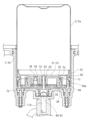
- FIG. 2 is an external perspective view showing a part of the inside of the water discharge device.
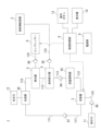
- 4 is a block diagram showing an example of the configuration of a water channel system and an electric circuit system of the water discharge device.
- FIG. FIG. 2 is an exploded perspective view of the liquid supply container.
- FIG. 2 is a vertical cross-sectional view of the liquid supply container.
- FIG. 2 is an external perspective view of a supply valve.
- FIG. FIG. FIG. 4 is an enlarged vertical cross-sectional view of a supply valve portion.
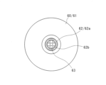
- FIG. 13 is a plan view showing the mouth of the supply valve with the plug inserted therein;
- the water discharge device 1 houses pipes and various parts inside a rectangular parallelepiped case 10.
- a hose 81 extending from a water supply device 80 is connected to a water supply port 11 of the water discharge device 1, and water is supplied from the water supply device 80.
- the water supply device 80 has, for example, a temperature adjustment function, a flow rate adjustment function, and a switching function between passing water and stopping water.
- the water discharge device 1 has a hose 82 of a shower head 83 connected to the water outlet 12.
- the water discharge device 1 discharges either water or bubbles from the water outlet 12, and either water or bubbles is discharged from the shower head 83 to the outside through the hose 82.
- the water discharge device 1 may be connected to a device other than the shower head 83.
- the water discharge device 1 may directly discharge either water or bubbles to the outside.
- the water discharge device 1 may be configured to include discharge components such as the shower head 83.
- the water discharge device 1 may have all of the functions of the water supply device 80.
- the water discharge device 1 may have some of the functions of the water supply device 80.
- the water discharge device 1 is removably connected to a liquid supply container 2 for supplying liquid containing a foaming component.
- An operation button 13 that can be operated by the user and a display 14 that can be seen by the user are arranged on the front of the case 10.
- the display 14 is composed of components such as an LED and an LCD display.
- the size of the case 10 is, for example, approximately 15 cm in height, 20 cm in width, and 5 cm in depth. The size of the case 10 is not limited to this.
- the water discharge device 1 includes a switch 3, a liquid suction device 4, a foaming device 5, a compressor 6, a container mounting section 7, a control circuit section 8, and a power source 9.
- a check valve 90 is connected downstream of the water supply port 11, and the check valve 90 and the switch 3 are connected by a flow path 110. The check valve 90 prevents water from flowing back from the flow path 110 to the water supply port 11.
- the switch 3 switches the flow of water to two flow paths 111 and 112 that branch off from the flow path 110.
- One of the flow paths 111 is connected to the junction 92.
- a check valve 91 provided in the flow path 111 prevents backflow from the junction 92 side to the switch 3 side.
- a flow rate regulator 93 and a check valve 94 are provided in the other flow path 112.
- the flow path 112 is connected to the liquid aspirator 4.
- the flow rate regulator 93 is composed of a constant flow rate valve, a pressure reducing valve, etc.
- the flow rate regulator 93 adjusts the flow rate on the downstream side to about 1 liter per minute, for example.
- the check valve 94 prevents backflow from the liquid aspirator 4 side to the switch 3 side.
- the liquid aspirator 4 is, for example, an ejector.
- the liquid aspirator 4 aspirates the liquid supplied from the liquid supply container 2 into the water flowing in from the flow path 112, mixes it, and sends it to the downstream flow path 113.
- the liquid supply container 2 and the liquid aspirator 4 are connected by a flow path 114.
- a check valve 95 is arranged in the flow path 114 to prevent backflow from the liquid aspirator 4 side to the liquid supply container 2 side.
- the flow path 113 is connected to the foamer 5.
- the flow path 113 supplies mixed water, which is a mixture of water and a liquid containing foaming components, to the foamer 5.
- the foamer 5 generates bubbles by mixing the mixed water supplied from the flow path 113 with compressed air from the compressor 6, and sends the bubbles to the flow path 115.
- the compressor 6 sends compressed air to the foamer 5 through the air flow path 116.
- a check valve 96 is arranged in the flow path 116 to prevent backflow from the foamer 5 side to the compressor 6 side.
- the junction 92 is a flow path that joins the flow path 111 and the flow path 115 and connects to the water outlet 12. As described above, the hose 82 of the shower head 83 is connected to the water outlet 12.
- the control circuit unit 8 receives power from the power source 9 and operates the switch 3, compressor 6, etc.
- the power source 9 is, for example, a variety of batteries such as a lithium-ion battery.
- the power source 9 may also be configured as a power supply circuit for using power supplied from a household power source.
- the control circuit unit 8 accepts operation input from the connected operation button 13 and operates the switch 3, compressor 6, etc.
- the control circuit unit 8 also displays information such as the operating status of the water discharge device 1 and the remaining power of the power source 9 on the display 14.
- the water discharger 1 discharges water supplied from the water supply device 80 through the flow path 111 from the water outlet 12 without generating bubbles. By switching at the switch 3, the water discharger 1 generates bubbles through the flow paths 112, 113, and 115 and discharges them from the water outlet 12. The water discharger 1 discharges fine bubbles by forming fine bubbles using the foaming device 5.
- the water discharge device 1 switches between a first discharge state in which the supplied water is discharged and a second discharge state in which the supplied water is discharged with a fluid containing an additive.
- the fluid containing an additive in the second discharge state may contain air.
- the water discharge device 1 may cause the supplied water to contain a liquid having a foaming component as the fluid containing an additive in the supplied water in the second discharge state, and may further cause air to be contained to generate foam and discharge the foam from the water discharge port 12.
- the water discharge device 1 may cause the supplied water to contain various additives for washing the user's body, beauty, and health promotion, etc.
- the water discharge device 1 may replace the foamer 5 with an ejector and the compressor 6 with an air intake mechanism.
- the liquid supply container 2 contains liquid additives to be added to the water supplied to the water discharge device 1.
- the liquid supply container 2 is detachable from the water discharge device 1, and can be replaced with a new one when the liquid inside the container runs out.
- the water discharge device 1 can be used by preparing multiple liquid supply containers 2 filled with liquids with different scents, and by replacing the liquid supply container 2 according to the user's mood before the liquid runs out.
- the water discharge device 1 can be made smaller by attaching and detaching the liquid supply container 2 to supply additives.
- the liquid supply container 2 has a container body 2a, a lid 20, a supply valve 50, and an intake valve 55.
- the container body 2a is a cylindrical hollow container that contains liquid inside.
- the container body 2a has a cylindrical opening 2b.
- the lid 20 is attached to the opening 2b.
- the lid 20 has an inner lid 21 and an outer lid 22, and is attached so as to cover the opening 2b.
- the inner lid 21 is a flattened cylinder with multiple valve holes 33, 34 penetrating the bottoms 31, 32.
- Valve hole 33 is located in the center, and valve hole 34 is located in an eccentric position.
- a supply valve 50 is attached to the valve hole 33.
- An intake valve 55 is attached to the valve hole 34.
- the inner lid 21 has side walls 35, 36.
- the side wall 35 is cylindrical, and a bottom 31 is formed at the end on the container body 2a side.
- the side wall 35 fits into the inside of the opening 2b of the container body 2a.
- the side wall 36 has a larger diameter than the side wall 35, and fits into the outside of the opening 2b of the container body 2a.
- the outer lid 22 is a flattened cylinder and is attached to cover the inner lid 21.
- the side wall 41 of the outer lid 22 is fitted to the inner surface of the container attachment part 7 provided on the water discharge device 1 side.
- the bottom 42 of the outer lid 22 has valve holes 43, 44 that penetrate the bottom 42 at positions corresponding to the valve holes 33, 34 of the inner lid 21.
- the bottom 42 has claws 45 that are hooked onto the side wall 36 of the inner lid 21 at each of four equal positions in the circumferential direction.
- the outer lid 22 has an attachment part 46 formed by drilling the side wall 41.
- the side wall 35 of the inner lid 21 fits tightly against the inside of the opening 2b of the container body 2a.
- the side wall 36 of the inner lid 21 is prevented from coming off by fitting into an annular protrusion 2c provided on the outside of the opening 2b of the container body 2a.
- the claw 45 of the outer lid 22 is hooked onto the side wall 36 of the inner lid 21.
- the mounting portion 46 of the outer lid 22 has a protrusion 46a.
- a claw 71 formed on the inside of the side wall 70 of the container mounting portion 7 is hooked onto the protrusion 46a.
- the container attachment section 7 has a plug section 60 provided at the bottom 72.
- the plug 63 of the plug section 60 extends towards the liquid supply container 2 and is inserted into the supply valve 50.
- the supply valve 50 is opened when the plug 63 is inserted.
- the supply valve 50 is opened, the liquid contained in the liquid supply container 2 flows through the plug 63 into the flow path 114.
- the supply valve 50 and the intake valve 55 are held in place by being sandwiched between the inner lid 21 and the outer lid 22.
- the supply valve 50 and the intake valve 55 are made of an elastic material such as rubber and have the same structure.
- the supply valve 50 and the intake valve 55 are duckbill valves, for example.
- the supply valve 50 will be described below as an example.
- the supply valve 50 has a sealing portion 51, a base portion 52, and a mouth portion 53, and is formed into a cylindrical shape as a whole.
- the sealing portion 51 is cylindrical, and has a flange portion 51a that extends outward from one end. The other end of the sealing portion 51 is continuous with the base portion 52.
- the sealing portion 51 is provided on the outer side of the mouth portion 53 when viewed from the container body 2a side.
- the base portion 52 is hollow and extends like a spatula, continuing into the mouth portion 53.
- the mouth portion 53 has a slit 53a.
- the mouth portion 53 is closed when the peripheral portions 53b, 53c on both sides of the slit 53a come into close contact with each other.
- the mouth portion 53 is in a closed state when no load is applied and in a free state.
- the mouth 53 is opened by elastic deformation of the peripheral portions 53b, 53c in a direction receding from the slit 53a.
- the direction in which the peripheral portions 53b, 53c deform when the mouth 53 is opened is perpendicular to the extension direction of the slit 53a and the central axis direction of the supply valve 50.
- the central axis direction of the supply valve 50 is the same as the insertion direction of the plug 63 on the container attachment portion 7 side relative to the supply valve 50.
- the mouth 53 is opened by elastic deformation of the peripheral portions 53b, 53c in a direction intersecting the insertion direction of the plug 63 inserted into the supply valve 50.
- the plug 60 has a plug body 61, a body 62, and a plug 63.
- the plug body 61 is cylindrical, and has a flow path formed therein for liquid to flow through.
- the body 62 is cylindrical, and extends from the plug body 61 toward the liquid supply container 2.
- the inside of the body 62 is connected to the inside of the plug body 61.
- the plug 63 is rod-shaped, and extends from the end 62a of the body 62 toward the liquid supply container 2, and is supported by the body 62. In a cross section intersecting the central axis direction, the plug 63 has a perforated outer surface, leaving plate-shaped members on two perpendicular diameters.
- a number of through holes 62b are formed between the end 62a of the body 62 and the stopper 63.
- the through holes 62b communicate with the interior of the body 62 and the interior of the stopper body 61.
- the liquid supplied from the liquid supply container 2 flows through the multiple through holes 62b, the interior of the body 62, and the interior of the stopper body 61 to the flow path 114.
- the liquid supply container 2 Before attaching the liquid supply container 2 to the water discharge device 1, the liquid supply container 2 can be carried in any position. For example, the user may hold the liquid supply container 2 with the lid portion 20 facing up, or may hold it upside down.
- the supply valve 50 of the liquid supply container 2 is in a free state and closed.
- the intake valve 55 is also in a free state and closed.
- the plug 63 With the liquid supply container 2 attached to the water discharge device 1, the plug 63 is inserted into the supply valve 50.
- the mouth 53 of the supply valve 50 opens when the plug 63 is inserted.
- the peripheral edges 53b, 53c of the mouth 53 elastically deform in a direction intersecting the insertion direction of the plug 63, and the slit 53a opens.
- a gap 54 is created between the mouth 53 and the plug 63.
- the liquid in the container body 2a flows out from the gap 54 and is supplied to the water discharge device 1 through the through hole 62b of the plug portion 60.
- the liquid supply container 2 is closed and open by inserting and removing the plug 63 into the supply valve 50, which is advantageous in simplifying the structure of the valve portion and reducing costs.
- the sealing portion 51 of the supply valve 50 is fitted with the body portion 62 that supports the plug 63, and comes into contact with the body portion 62 to prevent leakage.
- the supply valve 50 is made of an elastic material such as rubber, and can be made to adhere closely to the body portion 62.
- the sealing portion 51 is prevented from shifting position by maintaining the position of the supply valve 50, and the function of preventing leakage can be maintained.
- the supply valve 50 is held in place by sandwiching the flange 51a between the inner lid 21 and the outer lid 22.
- the supply valve 50 can be held in place by the inner lid 21 and the outer lid 22 in a simple configuration.
- the intake valve 55 can be configured in the same way as the supply valve 50. As described above, when the lid 20 of the liquid supply container 2 is on the lower side, the intake valve 55 is closed. When the liquid in the container body 2a is supplied to the water discharge device 1 and the pressure in the container body 2a drops, air is sucked in through the intake valve 55. The intake valve 55 opens at the moment the air is sucked in. At the moment the intake valve 55 opens, the sucked in air holds the liquid in the container body 2a, preventing liquid leakage.
- the intake valve 55 is held in place by sandwiching the flange 51a between the inner lid 21 and the outer lid 22.
- the intake valve 55 can be held in place by the inner lid 21 and the outer lid 22 in a simple configuration.
- a duckbill valve can be used as the supply valve 50 and the intake valve 55.
- the duckbill valve is used as a check valve.
- a duckbill valve as the valve element that opens and closes with the plug 63, the liquid supply container 2 can simplify the structure of the valve portion at low cost, thereby reducing costs.
- the supply valve 50 and the intake valve 55 use the cylindrical body of the duckbill valve as the sealing part 51 to prevent leakage of liquid when in the open state, and the structure of the valve part can be simplified.
- the supply valve 50 and the intake valve 55 are not limited to being cylindrical, but may be polygonal.
- the container body 2a and the inner lid 21 and the outer lid 22 of the lid portion 20 are not limited to being cylindrical, but may be polygonal.
- the supply valve 50 and the intake valve 55 may be held by either the inner lid 21 or the outer lid 22.
- the shape of the plug 63 provided in the container attachment portion 7 of the water discharge device 1 is not limited to the above example.
- the plug 63 can be of any shape that creates a gap 54 between the plug 63 and the mouth 53 of the supply valve 50 when inserted into the supply valve 50.
- the first item is a liquid supply container comprising a container body that contains liquid to be supplied to a water discharge device, a lid that covers the opening of the container body and has a valve hole formed therein, and a supply valve that fits into the valve hole and into which a plug provided on the water discharge device is inserted, the supply valve having a mouth that is in a closed state in a free state, and when the plug is inserted into the mouth, the periphery of the mouth elastically deforms in a direction intersecting the insertion direction of the plug, opening the supply valve.
- the second item is the liquid supply container described in the first item, in which the supply valve has a sealing portion on the outer side of the mouth when viewed from the side of the container body, which contacts the body portion that supports the stopper and prevents liquid leakage.
- the third item is a liquid supply container described in any one of the first and second items, in which the lid portion has an inner lid and an outer lid, and the supply valve is held by being sandwiched between the inner lid and the outer lid.
- the fourth item is the liquid supply container described in the third item, which is provided with an intake valve that is fitted into the valve hole of the inner lid and is held in a sandwiched manner between the inner lid and the outer lid.
- the fifth item is a liquid supply container described in any one of the first to fourth items, in which the supply valve is a duckbill valve.
- the sixth item is a liquid supply container described in any one of the fourth to fifth items, in which the intake valve is a duckbill valve.
- This disclosure relates to a liquid refill container and can be used in a liquid refill container.
Landscapes
- Engineering & Computer Science (AREA)
- Mechanical Engineering (AREA)
- General Engineering & Computer Science (AREA)
- Details Of Rigid Or Semi-Rigid Containers (AREA)
- Closures For Containers (AREA)
Priority Applications (3)
| Application Number | Priority Date | Filing Date | Title |
|---|---|---|---|
| PCT/JP2023/010870 WO2024194982A1 (ja) | 2023-03-20 | 2023-03-20 | 液体補給容器 |
| JP2025507955A JPWO2024194982A1 (https=) | 2023-03-20 | 2023-03-20 | |
| CN202380090387.1A CN120418192A (zh) | 2023-03-20 | 2023-03-20 | 液体补给容器 |
Applications Claiming Priority (1)
| Application Number | Priority Date | Filing Date | Title |
|---|---|---|---|
| PCT/JP2023/010870 WO2024194982A1 (ja) | 2023-03-20 | 2023-03-20 | 液体補給容器 |
Publications (1)
| Publication Number | Publication Date |
|---|---|
| WO2024194982A1 true WO2024194982A1 (ja) | 2024-09-26 |
Family
ID=92841154
Family Applications (1)
| Application Number | Title | Priority Date | Filing Date |
|---|---|---|---|
| PCT/JP2023/010870 Ceased WO2024194982A1 (ja) | 2023-03-20 | 2023-03-20 | 液体補給容器 |
Country Status (3)
| Country | Link |
|---|---|
| JP (1) | JPWO2024194982A1 (https=) |
| CN (1) | CN120418192A (https=) |
| WO (1) | WO2024194982A1 (https=) |
Citations (4)
| Publication number | Priority date | Publication date | Assignee | Title |
|---|---|---|---|---|
| US4948092A (en) * | 1990-03-07 | 1990-08-14 | Royce Medical Company | Combined check valve and fluid pressure relief valve |
| US20070131725A1 (en) * | 2005-11-10 | 2007-06-14 | Friedman Mitchell A | Dispensing valve for fluids stored under pressure |
| JP3167236U (ja) * | 2011-01-31 | 2011-04-14 | 寶徳醫療器材股▲分▼有限公司 | カモノハシの口ばし型液体逆止弁 |
| JP2012508676A (ja) * | 2008-11-17 | 2012-04-12 | レキット アンド コールマン (オーバーシーズ) リミテッド | ディスペンサおよび補給ユニット |
-
2023
- 2023-03-20 JP JP2025507955A patent/JPWO2024194982A1/ja active Pending
- 2023-03-20 CN CN202380090387.1A patent/CN120418192A/zh active Pending
- 2023-03-20 WO PCT/JP2023/010870 patent/WO2024194982A1/ja not_active Ceased
Patent Citations (4)
| Publication number | Priority date | Publication date | Assignee | Title |
|---|---|---|---|---|
| US4948092A (en) * | 1990-03-07 | 1990-08-14 | Royce Medical Company | Combined check valve and fluid pressure relief valve |
| US20070131725A1 (en) * | 2005-11-10 | 2007-06-14 | Friedman Mitchell A | Dispensing valve for fluids stored under pressure |
| JP2012508676A (ja) * | 2008-11-17 | 2012-04-12 | レキット アンド コールマン (オーバーシーズ) リミテッド | ディスペンサおよび補給ユニット |
| JP3167236U (ja) * | 2011-01-31 | 2011-04-14 | 寶徳醫療器材股▲分▼有限公司 | カモノハシの口ばし型液体逆止弁 |
Also Published As
| Publication number | Publication date |
|---|---|
| JPWO2024194982A1 (https=) | 2024-09-26 |
| CN120418192A (zh) | 2025-08-01 |
Similar Documents
| Publication | Publication Date | Title |
|---|---|---|
| EP1135214B1 (en) | A gear pump and replaceable reservoir for a fluid sprayer | |
| AU2002343237B2 (en) | Foam dispenser, housing and storage holder therefor | |
| KR100191879B1 (ko) | 복수 유체의 동시 분배 장치 및 분배 방법 | |
| US8770443B2 (en) | Foam pump | |
| EP2209558B1 (en) | Device for dispensing fluid | |
| CN100496758C (zh) | 通气式分发器 | |
| DE60116347D1 (de) | Flüssigkeitsabgabeverschlusselement | |
| KR20000023592A (ko) | 이중 분배 밸브 조립체 | |
| PL193402B1 (pl) | Urządzenie do wytwarzania i dozowania piany | |
| RU2008134482A (ru) | Сжимаемый вспениватель | |
| JPH0686952A (ja) | 化学剤吸引システム | |
| US10919676B2 (en) | Lid with ventilation system | |
| WO2024194982A1 (ja) | 液体補給容器 | |
| CN1971045A (zh) | 膜盒泵装置 | |
| US6712241B1 (en) | Flexible-pouch support and dispenser containing said support | |
| WO2025074635A1 (ja) | バルブおよび液体補給容器 | |
| WO2024117269A1 (ja) | 液体補給容器 | |
| JP3154499U (ja) | 小型噴霧器 | |
| JP2018052527A (ja) | スクイズ式泡ディスペンサおよびスクイズ式泡ディスペンサを備えた容器 | |
| JP6994924B2 (ja) | 自動スプレーおよび自動スプレー製品 | |
| CN224179182U (zh) | 一种油仓组件 | |
| JP3710617B2 (ja) | 泡噴出ポンプ | |
| JPH0811961A (ja) | 泡噴出容器 | |
| WO2025253625A1 (ja) | 液体補給容器 | |
| CN215959679U (zh) | 水箱及自移动机器人 |
Legal Events
| Date | Code | Title | Description |
|---|---|---|---|
| 121 | Ep: the epo has been informed by wipo that ep was designated in this application |
Ref document number: 23928565 Country of ref document: EP Kind code of ref document: A1 |
|
| WWE | Wipo information: entry into national phase |
Ref document number: 202380090387.1 Country of ref document: CN |
|
| WWP | Wipo information: published in national office |
Ref document number: 202380090387.1 Country of ref document: CN |
|
| ENP | Entry into the national phase |
Ref document number: 2025507955 Country of ref document: JP Kind code of ref document: A |
|
| WWE | Wipo information: entry into national phase |
Ref document number: 2025507955 Country of ref document: JP |
|
| NENP | Non-entry into the national phase |
Ref country code: DE |
|
| 122 | Ep: pct application non-entry in european phase |
Ref document number: 23928565 Country of ref document: EP Kind code of ref document: A1 |