WO2024190874A1 - ボルト - Google Patents
ボルト Download PDFInfo
- Publication number
- WO2024190874A1 WO2024190874A1 PCT/JP2024/010018 JP2024010018W WO2024190874A1 WO 2024190874 A1 WO2024190874 A1 WO 2024190874A1 JP 2024010018 W JP2024010018 W JP 2024010018W WO 2024190874 A1 WO2024190874 A1 WO 2024190874A1
- Authority
- WO
- WIPO (PCT)
- Prior art keywords
- less
- bolt
- shank
- ray diffraction
- max
- Prior art date
- Legal status (The legal status is an assumption and is not a legal conclusion. Google has not performed a legal analysis and makes no representation as to the accuracy of the status listed.)
- Ceased
Links
Images





Classifications
-
- C—CHEMISTRY; METALLURGY
- C22—METALLURGY; FERROUS OR NON-FERROUS ALLOYS; TREATMENT OF ALLOYS OR NON-FERROUS METALS
- C22C—ALLOYS
- C22C38/00—Ferrous alloys, e.g. steel alloys
- C22C38/04—Ferrous alloys, e.g. steel alloys containing manganese
-
- B—PERFORMING OPERATIONS; TRANSPORTING
- B21—MECHANICAL METAL-WORKING WITHOUT ESSENTIALLY REMOVING MATERIAL; PUNCHING METAL
- B21C—MANUFACTURE OF METAL SHEETS, WIRE, RODS, TUBES, PROFILES OR LIKE SEMI-MANUFACTURED PRODUCTS OTHERWISE THAN BY ROLLING; AUXILIARY OPERATIONS USED IN CONNECTION WITH METAL-WORKING WITHOUT ESSENTIALLY REMOVING MATERIAL
- B21C23/00—Extruding metal; Impact extrusion
-
- B—PERFORMING OPERATIONS; TRANSPORTING
- B21—MECHANICAL METAL-WORKING WITHOUT ESSENTIALLY REMOVING MATERIAL; PUNCHING METAL
- B21C—MANUFACTURE OF METAL SHEETS, WIRE, RODS, TUBES, PROFILES OR LIKE SEMI-MANUFACTURED PRODUCTS OTHERWISE THAN BY ROLLING; AUXILIARY OPERATIONS USED IN CONNECTION WITH METAL-WORKING WITHOUT ESSENTIALLY REMOVING MATERIAL
- B21C23/00—Extruding metal; Impact extrusion
- B21C23/01—Extruding metal; Impact extrusion starting from material of particular form or shape, e.g. mechanically pre-treated
-
- B—PERFORMING OPERATIONS; TRANSPORTING
- B21—MECHANICAL METAL-WORKING WITHOUT ESSENTIALLY REMOVING MATERIAL; PUNCHING METAL
- B21C—MANUFACTURE OF METAL SHEETS, WIRE, RODS, TUBES, PROFILES OR LIKE SEMI-MANUFACTURED PRODUCTS OTHERWISE THAN BY ROLLING; AUXILIARY OPERATIONS USED IN CONNECTION WITH METAL-WORKING WITHOUT ESSENTIALLY REMOVING MATERIAL
- B21C37/00—Manufacture of metal sheets, rods, wire, tubes, profiles or like semi-manufactured products, not otherwise provided for; Manufacture of tubes of special shape
-
- C—CHEMISTRY; METALLURGY
- C21—METALLURGY OF IRON
- C21D—MODIFYING THE PHYSICAL STRUCTURE OF FERROUS METALS; GENERAL DEVICES FOR HEAT TREATMENT OF FERROUS OR NON-FERROUS METALS OR ALLOYS; MAKING METAL MALLEABLE, e.g. BY DECARBURISATION OR TEMPERING
- C21D3/00—Diffusion processes for extraction of non-metals; Furnaces therefor
- C21D3/02—Extraction of non-metals
- C21D3/06—Extraction of hydrogen
-
- C—CHEMISTRY; METALLURGY
- C21—METALLURGY OF IRON
- C21D—MODIFYING THE PHYSICAL STRUCTURE OF FERROUS METALS; GENERAL DEVICES FOR HEAT TREATMENT OF FERROUS OR NON-FERROUS METALS OR ALLOYS; MAKING METAL MALLEABLE, e.g. BY DECARBURISATION OR TEMPERING
- C21D8/00—Modifying the physical properties of ferrous metals or ferrous alloys by deformation combined with, or followed by, heat treatment
- C21D8/06—Modifying the physical properties of ferrous metals or ferrous alloys by deformation combined with, or followed by, heat treatment during manufacturing of rods or wires
-
- C—CHEMISTRY; METALLURGY
- C21—METALLURGY OF IRON
- C21D—MODIFYING THE PHYSICAL STRUCTURE OF FERROUS METALS; GENERAL DEVICES FOR HEAT TREATMENT OF FERROUS OR NON-FERROUS METALS OR ALLOYS; MAKING METAL MALLEABLE, e.g. BY DECARBURISATION OR TEMPERING
- C21D9/00—Heat treatment, e.g. annealing, hardening, quenching or tempering, adapted for particular articles; Furnaces therefor
- C21D9/0093—Heat treatment, e.g. annealing, hardening, quenching or tempering, adapted for particular articles; Furnaces therefor for screws; for bolts
-
- C—CHEMISTRY; METALLURGY
- C21—METALLURGY OF IRON
- C21D—MODIFYING THE PHYSICAL STRUCTURE OF FERROUS METALS; GENERAL DEVICES FOR HEAT TREATMENT OF FERROUS OR NON-FERROUS METALS OR ALLOYS; MAKING METAL MALLEABLE, e.g. BY DECARBURISATION OR TEMPERING
- C21D9/00—Heat treatment, e.g. annealing, hardening, quenching or tempering, adapted for particular articles; Furnaces therefor
- C21D9/52—Heat treatment, e.g. annealing, hardening, quenching or tempering, adapted for particular articles; Furnaces therefor for wires; for strips ; for rods of unlimited length
-
- C—CHEMISTRY; METALLURGY
- C21—METALLURGY OF IRON
- C21D—MODIFYING THE PHYSICAL STRUCTURE OF FERROUS METALS; GENERAL DEVICES FOR HEAT TREATMENT OF FERROUS OR NON-FERROUS METALS OR ALLOYS; MAKING METAL MALLEABLE, e.g. BY DECARBURISATION OR TEMPERING
- C21D9/00—Heat treatment, e.g. annealing, hardening, quenching or tempering, adapted for particular articles; Furnaces therefor
- C21D9/52—Heat treatment, e.g. annealing, hardening, quenching or tempering, adapted for particular articles; Furnaces therefor for wires; for strips ; for rods of unlimited length
- C21D9/525—Heat treatment, e.g. annealing, hardening, quenching or tempering, adapted for particular articles; Furnaces therefor for wires; for strips ; for rods of unlimited length for wire, for rods
-
- C—CHEMISTRY; METALLURGY
- C22—METALLURGY; FERROUS OR NON-FERROUS ALLOYS; TREATMENT OF ALLOYS OR NON-FERROUS METALS
- C22C—ALLOYS
- C22C38/00—Ferrous alloys, e.g. steel alloys
-
- C—CHEMISTRY; METALLURGY
- C22—METALLURGY; FERROUS OR NON-FERROUS ALLOYS; TREATMENT OF ALLOYS OR NON-FERROUS METALS
- C22C—ALLOYS
- C22C38/00—Ferrous alloys, e.g. steel alloys
- C22C38/02—Ferrous alloys, e.g. steel alloys containing silicon
-
- C—CHEMISTRY; METALLURGY
- C22—METALLURGY; FERROUS OR NON-FERROUS ALLOYS; TREATMENT OF ALLOYS OR NON-FERROUS METALS
- C22C—ALLOYS
- C22C38/00—Ferrous alloys, e.g. steel alloys
- C22C38/06—Ferrous alloys, e.g. steel alloys containing aluminium
-
- C—CHEMISTRY; METALLURGY
- C22—METALLURGY; FERROUS OR NON-FERROUS ALLOYS; TREATMENT OF ALLOYS OR NON-FERROUS METALS
- C22C—ALLOYS
- C22C38/00—Ferrous alloys, e.g. steel alloys
- C22C38/14—Ferrous alloys, e.g. steel alloys containing titanium or zirconium
-
- C—CHEMISTRY; METALLURGY
- C22—METALLURGY; FERROUS OR NON-FERROUS ALLOYS; TREATMENT OF ALLOYS OR NON-FERROUS METALS
- C22C—ALLOYS
- C22C38/00—Ferrous alloys, e.g. steel alloys
- C22C38/18—Ferrous alloys, e.g. steel alloys containing chromium
- C22C38/40—Ferrous alloys, e.g. steel alloys containing chromium with nickel
- C22C38/58—Ferrous alloys, e.g. steel alloys containing chromium with nickel with more than 1.5% by weight of manganese
-
- F—MECHANICAL ENGINEERING; LIGHTING; HEATING; WEAPONS; BLASTING
- F16—ENGINEERING ELEMENTS AND UNITS; GENERAL MEASURES FOR PRODUCING AND MAINTAINING EFFECTIVE FUNCTIONING OF MACHINES OR INSTALLATIONS; THERMAL INSULATION IN GENERAL
- F16B—DEVICES FOR FASTENING OR SECURING CONSTRUCTIONAL ELEMENTS OR MACHINE PARTS TOGETHER, e.g. NAILS, BOLTS, CIRCLIPS, CLAMPS, CLIPS OR WEDGES; JOINTS OR JOINTING
- F16B35/00—Screw-bolts; Stay-bolts; Screw-threaded studs; Screws; Set screws
-
- C—CHEMISTRY; METALLURGY
- C21—METALLURGY OF IRON
- C21D—MODIFYING THE PHYSICAL STRUCTURE OF FERROUS METALS; GENERAL DEVICES FOR HEAT TREATMENT OF FERROUS OR NON-FERROUS METALS OR ALLOYS; MAKING METAL MALLEABLE, e.g. BY DECARBURISATION OR TEMPERING
- C21D2211/00—Microstructure comprising significant phases
- C21D2211/005—Ferrite
Definitions
- the present invention relates to a bolt.
- the bolt according to the present invention particularly relates to a non-heat treated bolt.
- High-strength bolts with a tensile strength of 800 MPa or more are used in various machinery such as automobiles, and in the civil engineering and construction fields in order to reduce weight, size, and costs.
- high-strength bolts are prone to hydrogen embrittlement, and in order to achieve high bolt strength, it is necessary to improve hydrogen embrittlement resistance as well as strength.
- Patent Documents 1 to 5 As a method for improving the hydrogen embrittlement resistance of high-strength parts such as high-strength bolts, a method is known in which the structure is made pearlite or bainite and strengthened by wire drawing, and many proposals have been made to date (for example, Patent Documents 1 to 5).
- One method for manufacturing high-strength bolts with a tensile strength of 800 MPa or more is to form a wire of alloy steel with added alloy elements such as Cr, Mo, and V into a specified shape, and then quench and temper it to produce a high-strength bolt.
- this method is costly in terms of heat treatment and is disadvantageous in terms of manufacturing costs.
- Patent Document 6 describes a method for manufacturing a non-tempered bolt, in which a rod-shaped metal material is preformed to form a bolt preform with a bulging pressing side, and then the bolt preform is formed so that the shaft volume of the bolt preform is larger than the shaft volume of the finished bolt.
- a rod-shaped metal material is preformed to form a bolt preform with a bulging pressing side, and then the bolt preform is formed so that the shaft volume of the bolt preform is larger than the shaft volume of the finished bolt.
- Even bolts manufactured by the method of Patent Document 6 have insufficient hydrogen embrittlement resistance.
- the present invention was made in consideration of the above circumstances, and aims to provide a bolt with a tensile strength of 800 MPa to 1700 MPa and excellent resistance to hydrogen embrittlement.
- the gist of the present invention is as follows. [1] The chemical composition, in mass%, is C: 0.18-0.80%, Si: 0.01 to 1.50%, Mn: 0.50-2.00%, Al: 0.005-0.080%, P: 0.030% or less, S: 0.030% or less, Ti: 0.005-0.100%, B: 0.0003 to 0.0050%, N: 0.0150% or less, O: 0.0100% or less, The balance is composed of Fe and impurities.
- a bolt having a ratio ⁇ MAX / ⁇ C of the half-width ⁇ C of an X-ray diffraction peak corresponding to the (211) plane of the ferrite phase at the center of the shank at a connection between the bolt head and the shank to the maximum value ⁇ MAX of the half-width ⁇ MAX of an X-ray diffraction peak corresponding to the (211) plane of the ferrite phase in a region from the surface of the connection to a depth of 500 ⁇ m toward the central axis of the shank , of 1.50 or less, and having a tensile strength of 800 to 1700 MPa.
- the chemical composition, in mass%, is C: 0.18-0.80%, Si: 0.01-1.50%, Mn: 0.50-2.00%, Al: 0.005-0.080%, P: 0.030% or less, S: 0.030% or less, Ti: 0.005-0.100%, B: 0.0003 to 0.0050%, N: 0.0150% or less, O: 0.0100% or less; Further, it contains one or more selected from the group consisting of the following groups A, B, and C: The balance is composed of Fe and impurities.
- a ratio ⁇ MAX / ⁇ C of a half-width ⁇ C of an X-ray diffraction peak corresponding to a (211) plane of the ferrite phase at the center of the shank of a connection portion between the bolt head and the shank to a maximum value ⁇ MAX of a half-width ⁇ MAX of an X-ray diffraction peak corresponding to a (211) plane of the ferrite phase in a region from the surface of the connection portion to a depth of 500 ⁇ m toward the central axis of the shank is 1.50 or less
- [Group A] One or more selected from the group consisting of Cr: 1.50% or less, Mo: 0.50% or less, Nb: 0.050% or less, V: 0.20% or less, and W: 0.20% or less.
- Group B One or two selected from the group consisting of Cu: 0.50% or less and Ni: 0.50% or less.
- [Group C] One or more selected from the group consisting of Ca: 0.0100% or less, Mg: 0.0100% or less, Ce: 0.020% or less, and Sn: 0.0400% or less.
- the present invention provides bolts with a tensile strength of 800 MPa to 1700 MPa and excellent resistance to hydrogen embrittlement.
- FIG. 1 is a schematic cross-sectional view of a shaft portion for explaining the measurement position of the area ratio of the hard structure of the steel of a bolt according to an embodiment of the present invention.
- FIG. 2 is a diagram showing measurement positions of ⁇ MAX / ⁇ C in a bolt according to a first modified example of an embodiment of the present invention, and is a schematic cross-sectional view including the central axis of the shank in the vicinity of the connection between the bolt head and the shank.
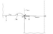
- FIG. 3 is a diagram showing measurement positions of ⁇ MAX / ⁇ C of a bolt according to an embodiment of the present invention, and is a schematic cross-sectional view including the central axis of the shank in the vicinity of the connection between the bolt head and the shank.
- FIG. 1 is a schematic cross-sectional view of a shaft portion for explaining the measurement position of the area ratio of the hard structure of the steel of a bolt according to an embodiment of the present invention.
- FIG. 2 is a diagram showing measurement positions of ⁇ MA
- FIG. 4 is a diagram showing measurement positions of ⁇ MAX / ⁇ C in a bolt according to a second modified example of an embodiment of the present invention, and is a schematic cross-sectional view including the central axis of the shank in the vicinity of the connection between the bolt head and the shank.
- FIG. 5 is a process diagram illustrating step 1 of the bolt manufacturing method according to the embodiment of the present invention.
- FIG. 6 is a process diagram illustrating step 2 of the bolt manufacturing method according to the embodiment of the present invention.
- FIG. 7 is a process diagram illustrating step 3 of the bolt manufacturing method according to the embodiment of the present invention.
- a bolt according to an embodiment of the present invention has a chemical composition, in mass %, of C: 0.18 to 0.80%, Si: 0.01 to 1.50%, Mn: 0.50 to 2.00%, Al: 0.005 to 0.080%, P: 0.030% or less, S: 0.030% or less, Ti: 0.005 to 0.100%, B: 0.0003 to 0.0050%, N: 0.0150% or less, O: 0.0100% or less, the balance: Fe and impurities, in which 95% or more of the metal structure at a position D/4, where D is a shank diameter, is a hard structure, and a half-width ⁇ of an X-ray diffraction peak corresponding to a (211) plane of ferrite at the center of the shank at a connection portion between the bolt head and the shank is 0.005 to 0.100%, and a half-width ⁇ of an X-ray diffraction
- the bolt has a tensile strength of 800 to 1700 MPa, and a ratio ⁇ MAX / ⁇ C of ⁇ MAX C to ⁇ MAX , the maximum half-width value of the X-ray diffraction peak corresponding to the (211) plane of ferrite in a region from the surface of the connection part to a depth of 500 ⁇ m toward the central axis of the shaft part, is 1.50 or less.
- the half-width of the X-ray diffraction peak corresponding to the (211) plane of ferrite does not change regardless of the position at which measurement is performed at the bolt head or around the connection between the bolt head and the shank (however, in the case of a bolt that forms a threaded portion by rolling after heat treatment, the half-width of the X-ray diffraction peak corresponding to the (211) plane of ferrite may change around the threaded portion.)
- the half-width of the X-ray diffraction peak corresponding to the (211) plane of ferrite changes depending on the position at which measurement is performed due to the effects of processing.
- Chemical composition The chemical composition of the steel of the bolt according to the embodiment of the present invention will be described below.
- the "%" for the content of each element in the chemical composition means “mass %”.
- a numerical range expressed using “to” means a range that includes the numerical values written before and after "to” as the lower and upper limits. Note that when “more than” or “less than” is added to the numerical values written before and after "to", the numerical range does not include these numerical values as the lower or upper limit.
- C is an element necessary for ensuring tensile strength. If the C content is less than 0.18%, it is difficult to obtain the desired tensile strength. Therefore, the lower limit of the C content is The C content is set to 0.18% or more, preferably 0.20% or more. If the C content exceeds 0.80%, the cold workability deteriorates. Therefore, the upper limit of the C content is set to The content is set to 0.80% or less, and preferably to 0.75% or less.
- Si is a deoxidizing element and also an element that increases tensile strength by solid solution strengthening. If the Si content is less than 0.010%, the effect of containing Si is not fully exerted. Therefore, The lower limit of the Si content is set to 0.01% or more, preferably 0.05% or more. If the Si content exceeds 1.50%, the effect of containing Si becomes saturated and the thermal The ductility during cold rolling is deteriorated, and surface defects are likely to occur. These surface defects may cause deterioration in cold workability. Therefore, the upper limit of the Si content is set to 1.50%. The content is preferably 1.00% or less.
- Mn manganese
- Mn is an element that promotes the transformation into a hard structure (bainite transformation) and increases the tensile strength of steel. If the Mn content is less than 0.50%, the effect of Mn is not sufficiently achieved. Therefore, the lower limit of the Mn content is set to 0.50% or more, and preferably 0.60% or more. In addition, when the Mn content exceeds 2.00%, martensite structure is locally formed. Therefore, the upper limit of the Mn content is set to 2.00% or less, and preferably 1.50% or less.
- Al 0.005-0.080%
- Al aluminum
- AlN refines the crystal grains, thereby improving the cold workability.
- Al Al is an element that has the effect of suppressing dynamic strain aging by reducing solute N, and the effect of enhancing hydrogen embrittlement resistance. Therefore, the Al content is set to 0.005% or more, and preferably 0. If the Al content exceeds 0.080%, the above-mentioned effects are saturated and coarse oxides such as Al 2 O 3 are formed, which may cause fatigue fracture. Therefore, the upper limit of the Al content is set to 0.080% or less, and preferably to 0.060% or less.
- P phosphorus
- P is an impurity element that is inevitably mixed into steel, and is an element that segregates at grain boundaries to deteriorate hydrogen embrittlement resistance and also deteriorates cold workability. Since such bolts do not need to contain P, the lower limit of the P content is 0%. However, from the viewpoint of reducing the manufacturing cost (dephosphorization cost), the P content may be more than 0%. If the P content exceeds 0.030%, hydrogen embrittlement resistance is deteriorated and cold workability is deteriorated. Therefore, the P content is limited to 0.030% or less, and preferably 0.015% or less.
- S sulfur
- S (sulfur) is an impurity element that, like P, is inevitably mixed into steel, and is an element that segregates at grain boundaries to deteriorate hydrogen embrittlement resistance and also deteriorates cold workability. Therefore, since the bolt according to this embodiment does not need to contain S, the lower limit of the S content is 0%. However, from the viewpoint of reducing the manufacturing cost (desulfurization cost), the S content is set to 0%. If the S content exceeds 0.030%, hydrogen embrittlement resistance is deteriorated, and The deterioration of cold workability becomes significant. Therefore, the S content is limited to 0.030% or less, preferably 0.015% or less, and more preferably 0.010% or less.
- Ti titanium
- Ti is a deoxidizing element and also forms TiN which functions as a pinning particle. Ti also has the effect of reducing solute N and suppressing dynamic strain aging, Ti is an element that has the effect of enhancing hydrogen embrittlement resistance. It also has the effect of suppressing the formation of BN in steel.
- the lower limit of the Ti content is set to 0.005% or more, preferably 0.007% or more, More preferably, it is 0.0010% or more.
- the amount of Ni is set to 0.100% or less, preferably 0.080% or less, and more preferably 0.040% or less.
- B boron
- B is an element that promotes the transformation into a hard structure (bainite transformation) and increases tensile strength.
- the B content is less than 0.0003%, the transformation into a hard structure (bainite transformation) is difficult. In this case, the formation of pro-eutectoid ferrite and pearlite structures may not be promoted, and excessive pro-eutectoid ferrite and pearlite structures may be formed during isothermal transformation treatment. Therefore, the lower limit of the B content is set to 0.0003% or more, and preferably 0.0005% or more.
- the B content exceeds 0.0050%, BN and Fe23 (BC) 6 are generated in the steel, and the cold workability may deteriorate. Therefore, the B content is set to 0.0050% or less, and preferably to 0.0030% or less.
- N nitrogen
- nitrogen is an element that deteriorates cold workability due to dynamic strain aging. Since the bolt according to the present embodiment does not need to contain N, the lower limit of the N content is 0%. However, from the viewpoint of reducing the production cost (denitrification cost), the N content may be more than 0%, may be 0.0002% or more, or may be 0.0005% or more. If the N content exceeds 0.0150%, the deterioration of cold workability due to dynamic strain aging is significant. Therefore, the N content is limited to 0.0150% or less, and preferably 0.0040% or less. be.
- Oxygen (O) is an impurity element that inevitably gets mixed into steel and exists in the steel as oxides of Al, Ti, etc.
- the bolt according to the present embodiment does not need to contain O, so The lower limit of the amount is 0%.
- the O content may be more than 0% or may be 0.0002% or more. If the O content exceeds 0.0100%, coarse oxides are formed in the steel, which makes it easy for fatigue fracture to occur. Therefore, the O content is set to 0.0100%.
- the content is preferably 0.0050% or less.
- the remainder excluding the above-mentioned elements is Fe and impurities.
- the impurities refer to components contained in raw materials or components mixed in during the manufacturing process, but not intentionally contained in the steel.
- the chemical composition of the steel of the bolt of this embodiment may contain one or more elements selected from the group consisting of Group A, Group B, and Group C below, in place of a portion of Fe.
- Group A One or more selected from the group consisting of Cr: 1.50% or less, Mo: 0.50% or less, Nb: 0.050% or less, V: 0.20% or less, and W: 0.20% or less.
- Group B One or two selected from the group consisting of Cu: 0.50% or less and Ni: 0.50% or less.
- Group C One or more selected from the group consisting of Ca: 0.0100% or less, Mg: 0.0100% or less, Ce: 0.020% or less, and Sn: 0.0400% or less.
- the chemical composition of the steel of the bolt of this embodiment may contain, in mass %, one or more of Cr, Mo, Nb, V, and W, instead of a portion of Fe. These elements promote the transformation to a hard structure (bainite transformation) and increase the tensile strength.
- Cr chromium
- the Cr content is preferably 0.02% or more, more preferably 0.03% or more, even more preferably 0.05% or more, and particularly preferably 0.10% or more. %, martensite structure may be locally generated, and cold workability may be deteriorated. Therefore, the Cr content is set to 1.50% or less, and preferably 1.30% or less. More preferably, it is 1.00% or less.
- Mo 0.50% or less
- Mo mobdenum
- Mo is an optional element that, like Cr, promotes the transformation into a hard structure (bainite transformation) and increases the tensile strength of steel.
- Mo mobdenum
- the Mo content is set to 0.50% or less, and preferably 0.40% or less. and more preferably 0.35% or less.
- Nb 0.050% or less
- Nb niobium
- the content of Nb is 0.002
- the Nb content is set to 0.050% or less, and preferably 0.040% or less.
- V 0.20% or less
- V vanadium
- the V content is preferably 0%.
- the V content is set to 0.20% or less, and preferably 0.15% or less.
- W tungsten
- the content of W is preferably 0. %, or 0.02% or more, more preferably 0.04% or more.
- the W content is set to 0.20% or less, and preferably 0.15% or less. be.
- the chemical composition of the steel of the bolt of this embodiment may contain one or both of Cu and Ni instead of a portion of Fe.
- Cu 0.50% or less
- Cu copper
- Cu is an optional element and may be contained when it is desired to improve hydrogen embrittlement resistance.
- Cu may be more than 0% or may be 0.02% or more. If the amount exceeds 0.50%, the hot ductility of the steel decreases, and surface defects tend to occur during wire rolling. These surface defects may cause deterioration in cold workability.
- the Cu content is set to 0.50% or less, and preferably to 0.35% or less.
- Ni 0.50% or less
- Ni nickel
- Cu copper
- Ni nickel
- Ni may be contained to suppress the deterioration of hot ductility of the steel material caused by Cu.
- Ni may be more than 0%.
- the Ni content is set to 0.50% or less, and preferably 0.35% or less.
- the chemical composition of the steel of the bolt of the present embodiment may contain one or more of Ca, Mg and Sn in place of a portion of Fe.
- Ca is an optional element.
- Ca is a deoxidizing element, and has the effect of making the shape of MnS in the steel spheroidal and improving the cold workability and machinability.
- Ca may be contained when it is desired to improve the steel sheet strength.
- Ca may be more than 0%, may be 0.0002% or more, or may be 0.0005% or more.
- the Ca content is set to 0.0100% or less, and preferably 0.0050% or less.
- Mg manganesium
- Mg is an optional element.
- Mg is a deoxidizing element and has the effect of making the shape of MnS in the steel material spherical and improving cold workability and machinability.
- Mg may be added when it is desired to improve the steel quality.
- Mg may be more than 0%, may be 0.0002% or more, or may be 0.0005% or more.
- the Mg content is set to 0.0100% or less, and preferably 0.0050% or less.
- Ce is an optional element.
- Ce is a deoxidizing element and has the effect of making the shape of MnS in the steel material spherical and improving cold workability and machinability.
- Ce may be added when it is desired to improve the steel quality.
- Ce may be more than 0%, 0.002% or more, or 0.005% or more.
- the Ce content is set to 0.020% or less, and preferably 0.015% or less.
- Sn (tin) is an optional element. Since Sn has the effect of improving corrosion resistance, it may be contained when it is desired to improve corrosion resistance. Sn may be more than 0%, and may be 0.0002% or more. On the other hand, if the Sn content exceeds 0.0400%, the hot ductility of the steel decreases, and surface defects are likely to occur during wire rolling. Therefore, the Sn content is set to 0.0400% or less, and preferably 0.0200% or less.
- the ratio ⁇ MAX / ⁇ C of the half-width ⁇ C of the X-ray diffraction peak corresponding to the (211) plane of ferrite at the center of the shank to the maximum value ⁇ MAX of the half-width of the X-ray diffraction peak corresponding to the (211) plane of ferrite in a region from the shank surface to a depth of 500 ⁇ m is 1.50 or less.
- the hard structure is a supercooled transformation structure obtained by isothermal transformation treatment. When observed with a scanning electron microscope, the hard structure is observed as a structure consisting of a ferrite phase in which a carbide phase is dispersed. The hard structure is sometimes called a bainite structure. The hard structure does not have a pearlite structure, which is a lamellar structure of a carbide phase and a ferrite phase. In addition, a martensite structure is not included in the hard structure in the present invention.
- the microstructure of the steel material of this embodiment when a structure other than a martensite structure, a pro-eutectoid ferrite structure, and a pearlite structure is defined as a "hard structure", if the area ratio of the hard structure in the microstructure is 95% or more and the tensile strength of the steel of the bolt is 800 to 1700 MPa, the microstructure of the steel of the bolt is substantially a hard structure.
- the hard structure has high strength and excellent workability. This improves the strength and cold workability of the steel of the bolt.
- the metal structure of the steel of the bolt according to this embodiment is continuously cooled after hot rolling and then isothermally transformed, so in addition to the hard structure, it may contain pro-eutectoid ferrite and pearlite structures.
- the pro-eutectoid ferrite and pearlite structures are clearly distinguished as hard structures by observation with a scanning electron microscope. If the area ratio of the pro-eutectoid ferrite and pearlite structures exceeds 5%, the metal structure becomes non-uniform, and cracks are likely to occur when the bolt is pressed into the shape.
- the pro-eutectoid ferrite and pearlite structures are preferably 5% or less, more preferably 1% or less, and may be 0%.
- a martensite structure is included in the metal structure, cracks are likely to occur when the bolt is pressed into the shape. Therefore, the metal structure must not contain a martensite structure. Martensite is observed as a white structure by a scanning electron microscope and is clearly distinguished as a hard structure.
- the area ratio (%) of hard tissue refers to a value determined by the following procedure.
- the C-section of the bolt shaft (a section perpendicular to the bolt shaft direction) is etched for 10 seconds using picral (a mixed solution of 4 g of picric acid per 100 ml of ethanol) to reveal the metal structure. If it is difficult to distinguish the structure, an additional etching of up to 10 seconds may be added.
- picral a mixed solution of 4 g of picric acid per 100 ml of ethanol
- an additional etching of up to 10 seconds may be added.
- four observation positions are selected at 90° intervals in the circumferential direction from a depth D/4 position (i.e., circumferential positions) from the shaft surface in the C cross section of the etched shaft, and SEM photographs are taken at 1000x magnification for each observation position using a FE-SEM (Field Emission-Scanning Electron Microscope).
- the ratio ⁇ MAX / ⁇ C of the half-width ⁇ C of the X-ray diffraction peak corresponding to the (211) plane of the ferrite phase at the center of the shank at the connection between the bolt head and the shank to the maximum value ⁇ MAX of the half-width ⁇ MAX of the X-ray diffraction peak corresponding to the (211) plane of the ferrite phase in the region from the surface of the connection to a depth of 500 ⁇ m toward the central axis of the shank is set to 1.50 or less.
- the inventors have conducted extensive research to improve the hydrogen embrittlement resistance of the bolt and have found a correlation between the half-width of the X-ray diffraction peak of the ferrite phase and the hydrogen embrittlement resistance. More specifically, they have found that the hydrogen embrittlement resistance of the bolt is excellent when ⁇ MAX / ⁇ C is 1.50 or less.
- ⁇ MAX / ⁇ C exceeds 1.50, the hydrogen embrittlement resistance of the bolt is insufficient, and fracture due to hydrogen embrittlement is likely to occur. It is preferably 1.40 or less, and more preferably 1.35 or less.
- the lower limit of ⁇ MAX / ⁇ C is not particularly specified, but from the viewpoint of manufacturability, it is preferably 0.50 or more. In addition, the lower limit of ⁇ MAX / ⁇ C may be 0.70 or more, or may be 0.80 or more.
- the half-width ⁇ C which is the denominator of ⁇ MAX / ⁇ C , is measured at the center of the shaft at the connection between the bolt head and the shaft.
- ⁇ MAX which is the numerator of ⁇ MAX / ⁇ C , is the maximum value among the half-widths of the X-ray diffraction peaks measured at multiple locations in the region from the surface of the connection between the bolt head and the shaft to a depth of 500 ⁇ m toward the central axis of the shaft.
- the bolt according to this embodiment is a so-called non-tempered bolt, and the strain introduced during cold working to finish the bolt shape remains in the bolt. Therefore, the half-width of the X-ray diffraction peak can change significantly depending on the measurement position.
- the reason for measuring the half-width ratio of the X-ray diffraction peak at the connection is that the connection between the bolt head and the shaft is a location that is susceptible to stress concentration and is likely to be the starting point of delayed fracture due to hydrogen embrittlement, and it has been found that it is possible to improve hydrogen embrittlement resistance by controlling the half-width ratio of the X-ray diffraction peaks at this connection.
- the measurement positions will be described with reference to the drawings.
- Fig. 2 is a schematic cross-sectional view illustrating the measurement positions of the full width at half maximum ⁇ MAX and the full width at half maximum ⁇ C.
- Fig. 2 shows an L cross section (a cross section parallel to the bolt axial direction) that is a cross section in the vicinity of the connection portion between the bolt head and the shank and includes the central axis of the shank.
- reference numeral 1 denotes the contour of the bolt seat in the L-section
- reference numeral 2 denotes the contour of the cylindrical portion in the L-section
- reference numeral 3 denotes the contour of the surface of the connection between the bolt head and the shank.
- the contour of the cylindrical portion is the contour of the incomplete thread portion.
- the contour 1 of the lower surface of the bolt head and the contour 2 of the surface of the shank are oriented in a mutually intersecting direction.
- the bolt seat refers to the surface portion that receives direct force when the threaded part is tightened (excluding the flank surface of the thread).
- the cylindrical portion refers to the cylindrical portion between the head and the threaded part of the male threaded part.
- the contour 1 and the contour 2 of the surface of the shank are almost perpendicular to each other, but as shown in another example described later, they do not necessarily have to be perpendicular to each other.
- the connection between the lower surface of the bolt head and the surface of the shank is a minute R surface
- the contour 3 of the surface of the connection can be approximately represented by a concave curve that connects the contours 1 and 2 extending in the intersecting direction.
- the extension of the contour line 1 of the underside of the bolt head is defined as l flg
- the extension of the contour line 2 of the surface of the shank is defined as l axis
- the intersection of the extension line l flg and the extension line l axis is defined as A.
- a line segment is drawn from the intersection point A toward the contour line 3 of the surface of the connection portion, and the intersection point between the line segment and the contour line 3 is O.
- the line segment drawn from the intersection point A toward the contour line 3 is a line segment that forms an angle of 45° with the extension line l flg .
- an extension line l measure parallel to the extension line l flg is extended from the intersection point O toward the central axis 4 of the shaft portion.
- the intersection point between the extension line l measure and the central axis 4 is defined as C.
- the intersection C is set as the measurement position of the half-value width ⁇ C. Also, as shown in FIG. 2, a region D extending from the intersection O along the extension line l measure to a depth of 500 ⁇ m is set as the measurement region of the half-value width ⁇ MAX .
- a cross section of the connection part near the connection part between the bolt head and the shaft part which is an L cross section of the connection part including the central axis of the bolt, is mirror-finished as described below. Then, an X-ray diffraction measurement is performed at the intersection C in Fig. 2, and the half-width of the X-ray diffraction peak corresponding to the (211) plane of the ferrite phase at the intersection C (half-width means FWHM: Full Width Half Maximum) is measured. The X-ray diffraction measurement is performed five times. The average value of the five half-widths obtained by the five measurements is defined as the half-width ⁇ C .
- five measurement positions are set from a region D up to a depth of 500 ⁇ m along the extension line l measure .
- five measurement positions are set at 100 ⁇ m, 200 ⁇ m, 300 ⁇ m, 400 ⁇ m, and 500 ⁇ m away from the intersection point O, and at each measurement position, the half width of the X-ray diffraction peak corresponding to the (211) plane of the ferrite phase (half width means FWHM: Full Width Half Maximum) is measured.
- the X-ray diffraction measurement is performed five times at each measurement point, and the average of the five measurements is taken as the half width at each measurement position. Then, the maximum half width of the half widths obtained at the five measurement positions is taken as the half width ⁇ MAX .
- the ferrite phase that is the subject of the measurement is mainly contained in the hard structure, and refers to ⁇ -Fe with a body-centered cubic structure. More specifically, it is the portion other than the carbides that make up the hard structure (sometimes called bainitic ferrite).
- the X-ray diffraction peak for the (211) plane of the ferrite phase is an X-ray diffraction peak that has a peak position within the range of 150 to 170° when X-ray diffraction measurement is performed under the following conditions.
- the diffraction profile obtained by the X-ray diffraction measurement is pre-processed by the following procedure: In the following, it is assumed that the measurement section of the X-ray diffraction measurement does not include any X-ray diffraction peak other than the X-ray diffraction peak corresponding to the (211) plane of the ferrite phase.
- the obtained diffraction profile is smoothed by the Savitsky-Golay method (A. Savitzky and M.J.E. Golay, Anal. Chem., 36 (1964), p.1627-1639.).
- the smoothing point number (corresponding to the value of 2m+1 in Savitzky and Golay (1964)) is set to 7.
- the intensity at the scan start angle and scan end angle of the X-ray diffraction measurement is used to connect the measurement start angle and the measurement end angle with a straight line, and the straight line is subtracted from the smoothed diffraction profile as the background.
- the Rachinger method (Rachinger, W. A., J. Sci. Instrum., 25 (1948), p.254-255.) is applied to the diffraction profile from which the background has been subtracted, and the X-ray diffraction peak corresponding to the K ⁇ 2 line is removed from the X-ray diffraction peak corresponding to the (211) plane of the ferrite phase in the diffraction profile from which the background has been subtracted.
- the intensity ratio of the X-ray diffraction peak corresponding to the K ⁇ 1 line and the X-ray diffraction peak corresponding to the K ⁇ 2 line was set to 2:1. From the diffraction profile obtained by the above procedure, the FWHM is obtained, and this is the half-width of the X-ray diffraction peak corresponding to the (211) plane of the ferrite phase at the measurement position.
- X-ray diffraction measurement conditions X-ray diffraction measurement conditions: Rigaku AutoMATE X-ray target: CrK ⁇ Acceleration voltage: 40 kV Acceleration current: 40mA Collimator diameter: ⁇ 150 ⁇ m X-ray scanning range (scan start angle to scan end angle): 146° to 165°
- the L-section of the bolt shaft is first wet-polished with emery paper (water-resistant silicon carbide abrasive paper) of #400 to #1500.
- emery paper water-resistant silicon carbide abrasive paper
- the test piece is then polished with a polishing cloth soaked in a diamond suspension (a liquid in which diamond powder with a grain size of 1 to 6 ⁇ m is dispersed in a diluent such as alcohol or pure water) to give the test piece a mirror finish.
- a diamond suspension a liquid in which diamond powder with a grain size of 1 to 6 ⁇ m is dispersed in a diluent such as alcohol or pure water
- the half-width of the X-ray diffraction peak corresponding to the (211) plane of the ferrite phase is measured in the center of the shaft and within a region up to 500 ⁇ m from the surface of the connection part (for example, five points at 100 ⁇ m, 200 ⁇ m, 300 ⁇ m, 400 ⁇ m, and 500 ⁇ m from the surface).
- the measurement start point is not the surface of the coating, but the surface of the base steel.
- the measurement start point is set so that the X-ray irradiation area at the measurement start point (a circular area with the same diameter as the collimator diameter) does not include any areas other than the base steel. In other words, the measurement start point is set so that the X-ray irradiation area at the measurement start point circumscribes the surface of the base steel.
- FIG. 3 Another example of a bolt is one in which the end of the shank on the head side is tapered, as shown in Figure 3.
- reference number 1 is the contour line of the bolt's seating surface in L-section
- reference number 2 is the contour line of the cylindrical portion in L-section
- reference number 3 is the contour line of the surface of the connection between the bolt head and shank.
- the contour line 1 of the underside of the bolt head and the contour line 2a of the tapered shape are oriented in directions that intersect with each other.
- the contour line 2a of the tapered portion of the shank is inclined relative to the contour line 2 of the shank by the amount of the tapered shape, and is not perpendicular to the contour line 1.
- the contour line 3 of the surface of the connection is approximately represented by a concave curve that connects the contour lines 1 and 2a that extend in the intersecting direction.
- the extension of the contour line 1 of the lower surface of the bolt head is designated as l flg
- the extension of the contour line 2a of the tapered portion of the shank is designated as l axis
- the intersection of the extension line l flg and the extension line l axis is designated as A.
- a line segment is drawn from the intersection point A toward the contour line 3
- the intersection point between the line segment and the contour line 3 is designated as O.
- the line segment drawn from the intersection point A toward the contour line 3 is a line segment that forms an angle of 45° with the extension line l flg .
- an extension line l measure that is parallel to the extension line l flg is extended from the intersection point O toward the central axis 4 of the shank.
- the intersection point between the extension line l measure and the central axis 4 is designated as C.
- the intersection point C is then designated as the measurement position of the half-value width ⁇ C.
- a region D extending from the intersection point O to a depth of 500 ⁇ m along the extension line l measure is defined as a measurement region for the half-value width ⁇ MAX .
- FIG. 4 another example of a bolt is a bolt in which the underside of the head is undercut at the connection between the shank and the head.
- reference numeral 1 denotes the contour of the bolt's seat in the L-section
- reference numeral 2 denotes the contour of the surface of the cylindrical portion in the L-section
- reference numeral 3a denotes the contour of the surface of the connection between the bolt head and the shank.
- the contour 3a is an undercut contour.
- Point B which is the connection point between the contour 2 of the shank and the contour 3a of the undercut shape, is located lower in the figure than the underside of the head.
- contour 1 of the underside of the head and the contour 2a of the shank are oriented in mutually orthogonal directions.
- the contour 3a of the surface of the connection is approximately represented by a concave curve that reflects the shape of the undercut and connects the contours 1 and 2a extending in the intersecting direction.
- the extension of the contour line 1 of the underside of the bolt head is designated as l flg
- the extension of the contour line 2 of the shank is designated as l axis
- the intersection of the extension line l flg and the extension line l axis is designated as A.
- a line segment is drawn from the intersection point A toward the contour line 3a, and the intersection point between the line segment and the contour line 3a is designated as O.
- the line segment drawn from the intersection point A toward the contour line 3a is a line segment that forms an angle of 45° with the extension line l flg .
- an extension line l measure that is parallel to the extension line l flg is extended from the intersection point O toward the central axis 4 of the shank.
- the intersection point between the extension line l measure and the central axis 4 is designated as C.
- the intersection point C is then designated as the measurement position of the half-value width ⁇ C.
- a region D extending from the intersection point O to a depth of 500 ⁇ m along the extension line l measure is defined as a measurement region for the half-value width ⁇ MAX .
- the tensile strength of the bolt according to this embodiment is in the range of 800 to 1700 MPa.
- the bolt according to this embodiment has excellent hydrogen embrittlement resistance, even though it is a bolt with a tensile strength of 800 MPa or more.
- the tensile strength is 1700 MPa or less, the bolt has excellent manufacturing suitability.
- the tensile strength of the steel of the bolt means the value measured in accordance with the test method described in JIS B 1051:2014.
- the bolt of this embodiment is made by a step of manufacturing the wire rod and steel wire, and a step of manufacturing the bolt from the obtained steel wire.
- a steel slab having the same chemical composition as the bolt according to the embodiment of the present invention is heated and hot rolled at a finish rolling temperature of more than 900° C. After hot rolling, the steel slab is cooled in the temperature section from the coiling end temperature to 500° C. at an average cooling rate of 10° C./sec or more (the time arithmetic mean of the cooling rate in the temperature section from the coiling end temperature to 500° C.). Then, a wire is obtained by performing isothermal holding (isothermal transformation treatment).
- the wire is immediately immersed in a molten salt bath at 350 to 500°C and maintained at a constant temperature.
- the immersion time in the molten salt bath is set to 5 to 150 seconds.
- the wire After being held in the molten salt bath for a specified time, the wire can be cooled by water cooling or naturally cooling. The same effect can be obtained even if a lead bath, fluidized bed or other equipment is used as the immersion bath instead of a molten salt bath.
- the steel wire is produced by drawing. At this time, the wire is drawn in a single pass or multiple passes, with a total reduction in area of 15 to 65%.
- the total reduction in area must be at least 15%. If the total reduction in area is too low, hydrogen embrittlement resistance may decrease. Also, sufficient tensile strength may not be obtained.
- the diameter of the steel wire to be manufactured is not particularly limited, and an appropriate diameter may be selected according to the dimensions of the bolt according to the embodiment of the present invention, but may be, for example, 10.0 mm or less.
- the diameter of the shaft of the bolt may also be 10.0 mm or less.
- the cold forging process consists of a shearing process, a forward extrusion process, a bolt head preforming process, and a bolt head finishing process. Each process will be explained with reference to Figures 5 to 7.
- the bolt of this embodiment is not limited to those manufactured by the manufacturing method described below, and even bolts manufactured by manufacturing methods other than the manufacturing method described below are included in the bolt of the present invention as long as the chemical composition, metal structure, and half-width ratio of the X-ray diffraction peaks (ratio ⁇ MAX / ⁇ C ) satisfy the ranges of the present invention.
- the resulting steel wire is cut and processed into blanks of the required length.
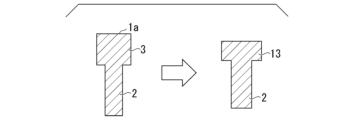
- a blank 1 is subjected to forward extrusion to draw a portion of the blank 1 into an extruded material 1a.
- the drawn portion 2 (forward extruded portion) of the extruded material 1a includes a portion that corresponds to the neck portion when the material is finished into the shape of a flanged hexagonal bolt.
- the bolt head is then formed through a bolt head preforming process and a bolt head finishing process (process 1).
- the area reduction ratio R in the forward extrusion process may be, for example, 0.10 or more.
- the area reduction ratio R is defined as ( A0 - A1 )/ A0 , where A0 is the cross-sectional area of the large diameter portion 3 of the extruded material 1a and A1 is the cross-sectional area of the drawn portion 2 of the extruded material 1a.
- the forward extrusion process adjusts the strain distribution of the bolt, and the ratio of the half widths of the X-ray diffraction peaks at the connection portion between the bolt head and the shank (ratio ⁇ MAX / ⁇ C ) can be set to 1.50 or less.
- the large diameter portion 3 (the portion not subjected to the forward extrusion process) of the forward extruded extrusion processed material 1a is swaged to form a preformed material 1b having a large diameter portion 13 that has been swaged.
- the outer diameter of the large diameter portion 13 is enlarged and the height of the large diameter portion 13 is reduced compared to the large diameter portion 3 of the extrusion processed material 1a (Process 2).
- the preformed material 1b after the bolt head preforming process is inserted into a finishing die bore 21 and swaged with a punch 20 to be processed into the final bolt shape.
- a knockout 22 is placed under the preformed material 1b to position the preformed material 1b.
- the punch 20 may have an appropriate die hole formed according to the bolt head shape to be formed. For example, when forming a flanged hexagonal bolt, a punch with a hexagonal die hole is used.
- the distance between the lower end 13a of the large diameter portion 13 (upset processing portion) and the upper end 21a of the finishing forming die bore 21 is preferably at least ( ⁇ L) mm and at most ( ⁇ L+r) mm.
- ⁇ L can be calculated using the following formula.
- S1 is the cross-sectional area of the shank of the preformed material 1b
- S2 is the cross-sectional area of the shank after the bolt head finishing process
- L2 is the length of the shank after the bolt head finishing process
- r is the radius of the shank after the bolt head finishing process.
- the distance between the lower end 13a and the upper end 21a is less than ( ⁇ L) mm, the ratio of the half widths of the X-ray diffraction peaks, ⁇ MAX / ⁇ C, may exceed 1.50, and if it exceeds ( ⁇ L + r) mm, buckling may occur during the bolt head finishing process. Therefore, the distance between the lower end 13a and the upper end 21a should be at least ( ⁇ L) mm and at most ( ⁇ L + r) mm.
- the ratio ⁇ MAX / ⁇ C of the half widths of the X-ray diffraction peaks at the connection between the bolt head and shank can be made 1.50 or less.
- the threads are formed on the bolt shaft by rolling.
- the bolt according to this embodiment has high strength even in this state, but in order to improve other mechanical properties required for a bolt, such as yield strength, yield ratio, and ductility, it may be held at 200 to 600°C for 10 to 300 minutes after being finished into the bolt shape, and then cooled. Note that this heat treatment does not fall under the category of heat treatment for refining.
- a coating such as electrolytic zinc plating may be applied to prevent rust. If hydrogen penetrates into the bolt due to the above-mentioned anti-rust coating, the bolt may be kept at 150-250°C for 60-480 minutes and then cooled as a heat treatment to release the hydrogen to the outside of the bolt. Note that this heat treatment does not fall under the category of heat treatment for tempering.
- a steel wire having the chemical composition according to the present invention is cold forged through the above-described shearing process, forward extrusion process, bolt head preforming process, and bolt head finishing process to form the steel wire into a bolt shape.
- This makes it possible to set the ratio ⁇ MAX / ⁇ C of the half-widths of the X-ray diffraction peaks at the connection between the bolt head and the shank to 1.50 or less, thereby making it possible to prevent delayed fracture originating from the connection due to hydrogen embrittlement.
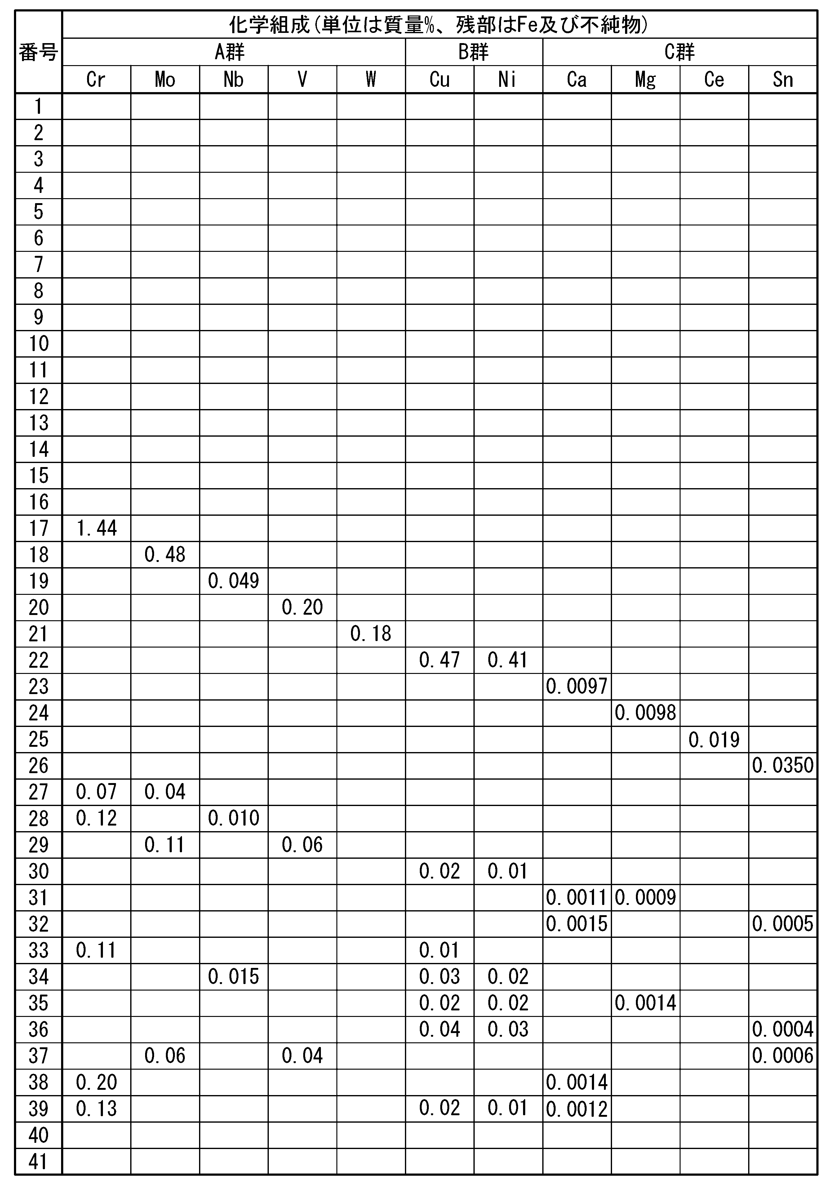
- steel billets having the chemical compositions shown in Tables 1A to 2B were used to manufacture steel wires in the following procedure.
- the balance other than the elements shown in Tables 1A to 2B is Fe and impurities.
- the chemical composition of the steel wire can be considered to be the same as the chemical composition of the steel billets. This is because the hot rolling, isothermal transformation treatment, water cooling, air cooling, and wire drawing included in the following procedure do not affect the chemical composition of the steel wire.
- the steel billets were hot-rolled under the conditions shown in Table 2, and cooled at an average cooling rate of 10°C/sec or more in the temperature range from the coiling end temperature to 500°C to obtain wires with the wire diameters shown in Table 2.
- steel wires were obtained by sequentially carrying out isothermal transformation treatment, water cooling, and wire drawing under the conditions shown in Tables 3A and 3B. Note that all levels were drawn in a single pass.
- each level of steel wire was cold worked (cold forged) under the conditions shown in Tables 3A and 3B to be processed into the shape of a flanged hexagonal bolt with a nominal diameter of 8.0 mm or 4.0 mm (M8 and M4 flanged hexagonal bolts as specified in JIS B1189:2015).
- Form 1 in Tables 3A and 3B was the condition for performing the cold working described below. That is, the shearing process, forward extrusion process, bolt head preforming process, and bolt head finishing process were performed.
- the shearing process the steel wire was cut to obtain a blank material.
- the blank material 1 was forward extruded to obtain an extruded material 1a having a drawn portion 2 and a large diameter portion 3.
- the reduction ratio was 0.12.
- the bolt head preforming process as shown in FIG. 6
- the large diameter portion 3 of the extruded material 1a was upset to obtain a preformed material 1b having a large diameter portion 13 that had been upset.
- the bolt head finishing process as shown in FIG.
- the preformed material 1b was inserted into a finishing die hole 21 and upset with a punch 20 with a hexagonal mold hole to obtain the final shape of a flanged hexagonal bolt.
- the lower end 13a of the large diameter portion 13 of the preform 1b was positioned so as not to come into contact with the upper end 21a of the finish forming die cavity 21.
- the distance between the lower end 13a of the large diameter portion 13 (upsetting processing portion) and the upper end 21a of the finish forming die cavity 21 was 0.45 mm.
- ⁇ L 0.30 mm.
- ⁇ L + r was more than 0.45 mm.
- the hydrogen embrittlement resistance of the obtained bolts was measured by the following method. First, the bolts were electrolytically hydrogen-charged to contain 0.5 ppm of diffusible hydrogen. The electrolytic hydrogen charging method was in accordance with ISO16573. Next, the samples were plated with Cd to prevent hydrogen from being released from the machine parts into the atmosphere during the test. Next, a load of 90% of the maximum tensile load of the bolt was applied to the bolts in the atmosphere, and the bolts were held in this state for 100 hours or more.
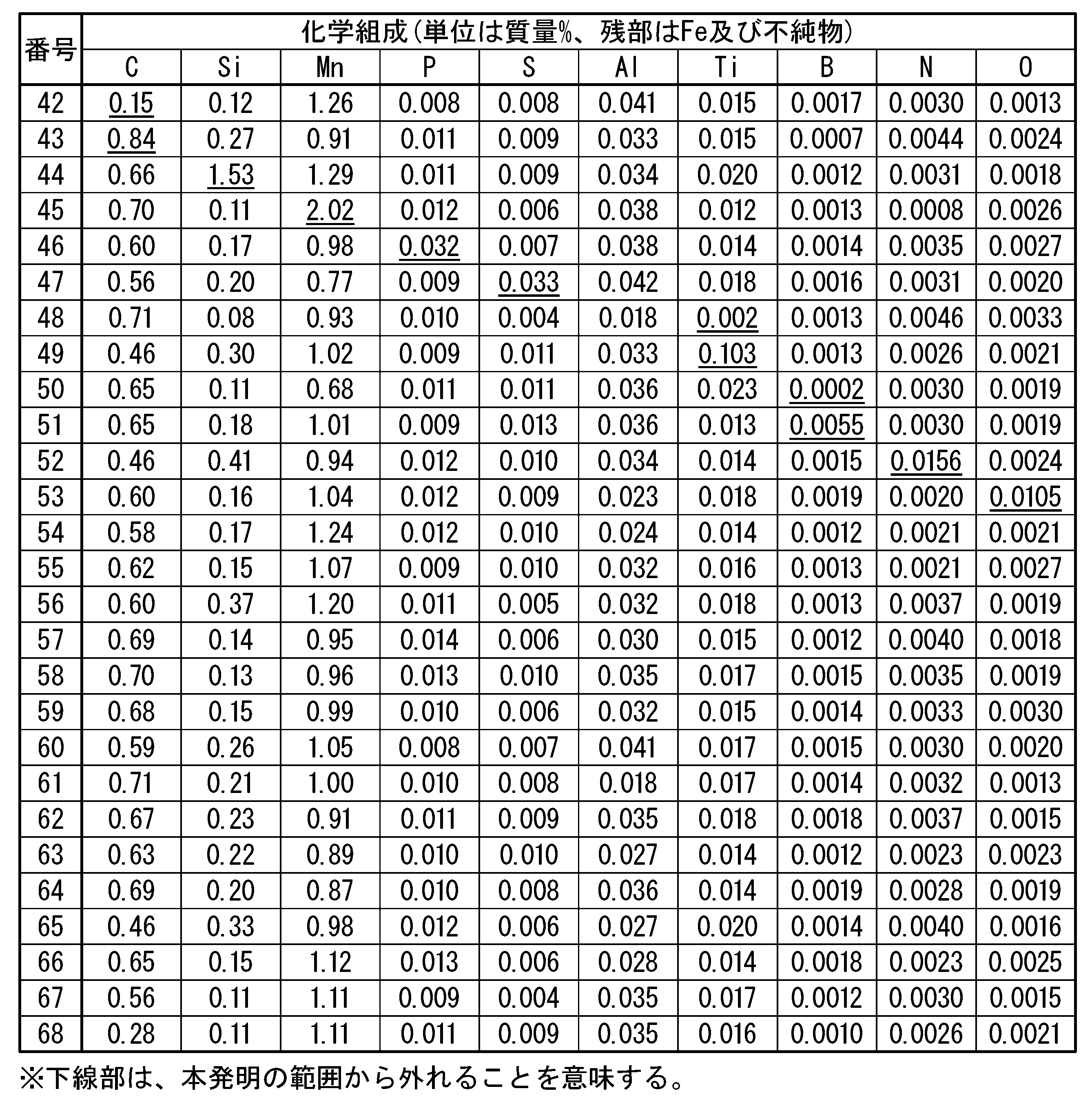
- Bolts of levels 42 to 63 did not fall within the chemical composition of the present invention. Therefore, as shown below, bolts of levels 42 to 63 did not have satisfactory tensile strength, cold workability, and hydrogen embrittlement resistance.
- the bolts of level 42 did not meet the tensile strength requirements of the bolts covered by this invention because the C content was outside the chemical composition of this invention.
- the bolts of level 43 had a C content outside the chemical composition of the present invention, so they cracked during forging and could not be evaluated for tensile strength and hydrogen embrittlement resistance.
- Bolts of levels 44, 48, 49, 51, 52, 53, 56 to 63 had Si, Ti, B, N, O, Nb, V, Ce, Cu, Ca, Mg, Sn, and W contents that were outside the chemical composition of the present invention, so cracks occurred during forging and it was not possible to evaluate the tensile strength and hydrogen embrittlement resistance.
- the bolts of level 50 had a B content outside the chemical composition of the present invention, so the area ratio of the hard structure at a depth of D/4 from the shaft surface was less than 95%, and the hard structure was mixed with ferrite, resulting in a non-uniform structure, which caused cracks during forging and made it impossible to evaluate the tensile strength and hydrogen embrittlement resistance.
- the bolts of levels 45, 54, and 55 had Mn, Cr, and Mo contents that fell outside the chemical composition of the present invention, so martensite formed locally and caused cracks during forging, making it impossible to evaluate the tensile strength and hydrogen embrittlement resistance.
- the bolts of level 64 were not subjected to isothermal transformation treatment and were left to cool naturally, so the area ratio of hard structure at a depth of D/4 from the shaft surface was less than 95%, which resulted in cracks occurring during forging and made it impossible to evaluate the tensile strength and hydrogen embrittlement resistance.
- the bolts of level 65 were not immersed in the molten salt bath for sufficient time during the isothermal transformation treatment, so martensite formed during the water cooling treatment after the isothermal transformation treatment, causing cracks during heading, making it impossible to evaluate the tensile strength and hydrogen embrittlement resistance.
- the bolts of Levels 66 and 67 were subjected to a cold forging process designed so that when the preformed bolt was inserted into the finish forming die cavity, the lower end of the expanded portion of the preformed bolt came into contact with the upper end of the finish forming die cavity.
- the ratio of the half widths of the X-ray diffraction peaks, ⁇ MAX / ⁇ C exceeded 1.50 and the bolts did not have sufficient resistance to hydrogen embrittlement.
- the bolts of level 68 were outside the tensile strength range of the present invention because the wire drawing conditions were not favorable.
- the bolts disclosed herein have a tensile strength of 800 MPa to 1,700 MPa and excellent resistance to hydrogen embrittlement, making them highly applicable in industry.
Landscapes
- Chemical & Material Sciences (AREA)
- Engineering & Computer Science (AREA)
- Mechanical Engineering (AREA)
- Materials Engineering (AREA)
- Metallurgy (AREA)
- Organic Chemistry (AREA)
- Physics & Mathematics (AREA)
- Thermal Sciences (AREA)
- Crystallography & Structural Chemistry (AREA)
- General Engineering & Computer Science (AREA)
- Manufacturing & Machinery (AREA)
- Heat Treatment Of Steel (AREA)
Abstract
Description
本願は、2023年3月15日に、日本に出願された特願2023-041287号に基づき優先権を主張し、その内容をここに援用する。
[1] 化学組成が、質量%で、
C:0.18~0.80%、
Si:0.01~1.50%、
Mn:0.50~2.00%、
Al:0.005~0.080%、
P:0.030%以下、
S:0.030%以下、
Ti:0.005~0.100%、
B:0.0003~0.0050%、
N:0.0150%以下、
O:0.0100%以下、
残部:Fe及び不純物からなり、
軸部直径をDとして、D/4位置における金属組織の95%以上が硬質組織であり、
ボルト頭部と前記軸部との接続部の軸部中心におけるフェライト相の(211)面に対応するX線回折ピークの半価幅βCと、前記接続部の表面から軸部の中心軸線に向かう深さ500μmまでの領域におけるフェライト相の(211)面に対応するX線回折ピークの半価幅の最大値βMAXとの比βMAX/βCが1.50以下であり、引張強さが800~1700MPaである、ボルト。
[2] 化学組成が、質量%で、
C:0.18~0.80%、
Si:0.01~1.50%、
Mn:0.50~2.00%、
Al:0.005~0.080%、
P:0.030%以下、
S:0.030%以下、
Ti:0.005~0.100%、
B:0.0003~0.0050%、
N:0.0150%以下、
O:0.0100%以下、を含有し、
更に、下記A群、B群及びC群からなる群から選択される1種又は2種以上を含有し、
残部:Fe及び不純物からなり、
軸部直径をDとして、D/4位置における金属組織の95%以上が硬質組織であり、
ボルト頭部と前記軸部との接続部の軸部中心におけるフェライト相の(211)面に対応するX線回折ピークの半価幅βCと、前記接続部の表面から軸部の中心軸線に向かう深さ500μmまでの領域におけるフェライト相の(211)面に対応するX線回折ピークの半価幅の最大値βMAXとの比βMAX/βCが1.50以下であり、
引張強さが800~1700MPaである、ボルト。
[A群]Cr:1.50%以下、Mo:0.50%以下、Nb:0.050%以下、V:0.20%以下、W:0.20%以下からなる群から選択される1種又は2種以上。
[B群]Cu:0.50%以下、Ni:0.50%以下からなる群から選択される1種又は2種。
[C群]Ca:0.0100%以下、Mg:0.0100%以下、Ce:0.020%以下、Sn:0.0400%以下からなる群から選択される1種又は2種以上。
[3] 質量%で、前記A群を含有する化学組成を有する[2]に記載のボルト。
[4] 質量%で、前記B群を含有する化学組成を有する[2]に記載のボルト。
[5] 質量%で、前記C群を含有する化学組成を有する[2]に記載のボルト。
本発明の実施形態に係るボルトは、化学組成が、質量%で、C:0.18~0.80%、Si:0.01~1.50%、Mn:0.50~2.00%、Al:0.005~0.080%、P:0.030%以下、S:0.030%以下、Ti:0.005~0.100%、B:0.0003~0.0050%、N:0.0150%以下、O:0.0100%以下、残部:Fe及び不純物からなり、軸部直径をDとして、D/4位置における金属組織の95%以上が硬質組織であり、ボルト頭部と軸部との接続部の軸部中心におけるフェライトの(211)面に対応するX線回折ピークの半価幅βCと、接続部の表面から軸部の中心軸線に向かう深さ500μmまでの領域におけるフェライトの(211)面に対応するX線回折ピークの半価幅の最大値βMAXとの比βMAX/βCが1.50以下であり、引張強さが800~1700MPaである、ボルトである。
熱処理を行ったボルトの場合、ボルト頭部や、ボルト頭部と軸部との接続部周辺では、どの位置で測定をしてもフェライトの(211)面に対応するX線回折ピークの半価幅が変わらない(ただし、熱処理を行った後に転造によりねじ部を形成するボルトの場合、ねじ部周辺でフェライトの(211)面に対応するX線回折ピークの半価幅が変化することがある)。本開示のボルトは、加工の影響により、測定する位置によって、フェライトの(211)面に対応するX線回折ピークの半価幅が変わる。
以下、本発明の実施形態に係るボルトの鋼の化学組成について説明する。以下の説明において、化学組成の各元素の含有量の「%」表示は、「質量%」を意味する。また、「~」を用いて表される数値範囲は、「~」の前後に記載される数値を下限値及び上限値として含む範囲を意味する。なお、「~」の前後に記載される数値に「超」または「未満」が付されている場合の数値範囲は、これら数値を下限値または上限値として含まない範囲を意味する。
Cは、引張強さを確保するために必要な元素である。C含有量が0.18%未満の場合、所望とする引張強さを得ることが困難である。よって、C含有量の下限を0.18%以上とする。好ましくは0.20%以上である。また、C含有量が0.80%超である場合、冷間加工性が劣化する。よって、C含有量の上限を0.80%以下とする。好ましくは0.75%以下である。
Si(珪素)は、脱酸元素であると共に、固溶強化により引張強さを高める元素である。Si含有量が0.010%未満である場合、Siの含有効果が十分に発現しない。よって、Si含有量の下限を0.01%以上とする。好ましくは0.05%以上である。また、Si含有量が1.50%超である場合、Siの含有効果が飽和すると共に、熱間圧延時の延性が劣化して表面疵が発生し易くなる。この表面疵に起因して、冷間加工性が低下する場合がある。よって、Si含有量の上限を1.50%以下とする。好ましくは1.00%以下である。
Mn(マンガン)は、硬質組織への変態(ベイナイト変態)を促進し、鋼の引張強さを高める元素である。Mn含有量が0.50%未満である場合、Mnの含有効果が十分に発現しない。よって、Mn含有量の下限を0.50%以上とする。好ましくは0.60%以上である。 また、Mn含有量が2.00%超である場合、局所的にマルテンサイト組織が生成し、冷間加工性が劣化する場合がある。よって、Mn含有量の上限を2.00%以下とする。好ましくは1.50%以下である。
Al(アルミニウム)は、脱酸元素であると共に、ピン止め粒子として機能するAlNを形成する元素である。AlNは結晶粒を細粒化し、これにより冷間加工性を高める。また、Alは、固溶Nを低減して動的ひずみ時効を抑制する作用、及び、耐水素脆化特性を高める作用を有する元素である。従って、Al含有量は0.005%以上とする。好ましくは0.010%以上である。また、Al含有量が0.080%超である場合、上述の効果が飽和すると共に、Al2O3などの粗大な酸化物が形成されて、疲労破壊の原因となる場合がある。よって、Al含有量の上限を0.080%以下とする。好ましくは0.060%以下である。
P(リン)は、不可避的に鋼に混入する不純物元素であり、結晶粒界に偏析して耐水素脆化特性を劣化させると共に、冷間加工性を劣化させる元素である。本実施形態に係るボルトはPを含有する必要がないので、P含有量の下限値は0%である。但し、製造コスト(脱リンコスト)の低減の観点から、P含有量は0%超であってもよく、0.002%以上であってもよく、0.005%以上であってもよい。P含有量が0.030%超の場合、耐水素脆化特性の劣化、及び、冷間加工性の劣化が顕著となる。よってP含有量は0.030%以下に制限する。好ましくは0.015%以下である。
S(硫黄)は、Pと同様に不可避的に鋼に混入する不純物元素であり、結晶粒界に偏析して耐水素脆化特性を劣化させると共に、冷間加工性を劣化させる元素である。従って、本実施形態に係るボルトはSを含有する必要がないので、S含有量の下限値は0%である。但し、製造コスト(脱硫コスト)の低減の観点から、S含有量は0%超であってもよく、0.002%以上であってもよく、0.005%以上であってもよい。S含有量が0.030%超では、耐水素脆化特性の劣化、及び、冷間加工性の劣化が顕著となる。従って、S含有量は0.030%以下に制限する。好ましくは0.015%以下であり、より好ましくは0.010%以下である。
Ti(チタン)は、脱酸元素であるとともに、ピン止め粒子として機能するTiNを形成する元素である。また、Tiは、固溶Nを低減して動的ひずみ時効を抑制する作用、及び、耐水素脆化特性を高める作用を有する元素である。また、鋼中のBNの生成を抑制する効果がある。Ti含有量が0.005%未満である場合、動的ひずみ時効による冷間加工性の劣化、耐水素脆化特性の劣化、鋼中のBNの過剰生成が発生する場合がある。よって、Ti含有量の下限を0.005%以上とする。好ましくは0.007%以上、より好ましくは0.0010%以上である。一方、Ti含有量が0.100%超である場合、上述の効果が飽和すると共に、熱間圧延の際に疵が発生し易くなる。従ってTi含有量は0.100%以下とする。好ましくは0.080%以下であり、より好ましくは0.040%以下である。
B(硼素)は、硬質組織への変態(ベイナイト変態)を促進させ、引張強さを高める元素である。B含有量が0.0003%未満である場合、硬質組織への変態(ベイナイト変態)が促進されず、恒温変態処理時に初析フェライト組織やパーライト組織が過剰に生成する場合がある。よって、B含有量の下限を0.0003%以上とする。好ましくは0.0005%以上であり、より好ましくは0.0007%以上である。一方、B含有量が0.0050%を超えると、鋼中にBNやFe23(BC)6などが生成し、冷間加工性が劣化する場合がある。従って、B含有量は0.0050%以下とする。好ましくは0.0030%以下である。
N(窒素)は、動的ひずみ時効により冷間加工性を劣化させる元素である。本実施形態に係るボルトはNを含有する必要がないので、N含有量の下限値は0%である。但し、製造コスト(脱窒コスト)の低減の観点から、N含有量は0%超であってもよく、0.0002%以上であってもよく、0.0005%以上であってもよい。N含有量が0.0150%超の場合、動的ひずみ時効による冷間加工性の劣化が顕著である。よってN含有量は0.0150%以下に制限する。好ましくは0.0040%以下である。
O(酸素)は、不可避的に鋼に混入する不純物元素であり、鋼中にAl及びTi等の酸化物として存在する。本実施形態に係るボルトはOを含有する必要がないので、O含有量の下限値は0%である。但し、製造コスト(脱酸コスト)の低減の観点から、O含有量は、0%超であってもよく、0.0002%以上であってもよく、0.0005%以上であってもよい。O含有量が0.0100%を超える場合、粗大な酸化物が鋼中に生成して、疲労破壊が生じ易い。従ってO含有量は0.0100%以下とする。好ましくは0.0050%以下である。
本実施形態のボルトの鋼の化学組成において、上述した各元素を除いた残部は、Fe及び不純物である。ここで、不純物とは、原材料に含まれる成分、又は、製造の工程で混入する成分であって、意図的に鋼に含有させたものではない成分を指す。
[A群]Cr:1.50%以下、Mo:0.50%以下、Nb:0.050%以下、V:0.20%以下、W:0.20%以下からなる群から選択される1種又は2種以上。
[B群]Cu:0.50%以下、Ni:0.50%以下からなる群から選択される1種又は2種。
[C群]Ca:0.0100%以下、Mg:0.0100%以下、Ce:0.020%以下、Sn:0.0400%以下からなる群から選択される1種又は2種以上。
本実施形態のボルトの鋼の化学組成は、Feの一部に代えて、質量%で、Cr、Mo、Nb、V、Wの1種又は2種以上を含有してもよい。これらの元素は、硬質組織への変態(ベイナイト変態)を促進させ、引張強さを高める元素である。
Cr(クロム)は、任意の元素であり、硬質組織への変態(ベイナイト変態)を促進させ、鋼の引張強さを高める元素である。Crの含有効果を発現するためには、より好ましくは0.02%以上であり、更に好ましくは0.03%以上であり、更に好ましくは0.05%以上であり、特に好ましくは0.10%以上である。一方、Cr含有量が1.50%超である場合、局所的にマルテンサイト組織が生成し、冷間加工性が劣化する場合がある。従ってCr含有量は1.50%以下とする。好ましくは1.30%以下であり、より好ましくは1.00%以下である。
Mo(モリブデン)は、任意の元素であり、Crと同様に硬質組織への変態(ベイナイト変態)を促進させ、鋼の引張強さを高める元素である。Moの含有効果を発現するためには、より好ましくは0.02%以上であり、更に好ましくは0.03%以上であり、更に好ましくは0.05%以上であり、特に好ましくは0.10%以上である。一方、Mo含有量が0.50%超である場合、局所的にマルテンサイトが生成し、冷間加工性が劣化する場合がある。従ってMo含有量は0.50%以下とする。好ましくは0.40%以下であり、より好ましくは0.35%以下である。
Nb(ニオブ)は、任意の元素であり、硬質組織への変態(ベイナイト変態)を促進させ、引張強さを高める元素である。Nbの含有効果を発現するためには、好ましくは0.002%以上である。一方、Nb含有量が0.050%超である場合、鋼の熱間延性が低下し、線材圧延時に表面疵が発生しやすくなる。この表面疵に起因して、冷間加工性が低下する場合がある。従ってNb含有量は0.050%以下とする。好ましくは0.040%以下である。
V(バナジウム)は、任意の元素であり、硬質組織への変態(ベイナイト変態)を促進させ、引張強さを高める元素である。これらの効果を得る観点から、V含有量は好ましくは0%超または0.02%以上であり、より好ましくは0.04%以上である。一方、V含有量が0.20%超である場合、鋼の熱間延性が低下し、線材圧延時に表面疵が発生しやすくなる。この表面疵に起因して、冷間加工性が低下する場合がある。したがって、V含有量は0.20%以下とする。好ましくは0.15%以下である。
W(タングステン)は、任意の元素であり、硬質組織への変態(ベイナイト変態)を促進させ、引張強さを高める元素である。これらの効果を得る観点から、Wの含有量は好ましくは0%超または0.02%以上であり、より好ましくは0.04%以上である。一方、Wの含有量が0.20%超である場合、鋼の熱間延性が低下し、線材圧延時に表面疵が発生しやすくなる。この表面疵に起因して、冷間加工性が低下する場合がある。したがって、Wの含有量は0.20%以下とする。好ましくは0.15%以下である。
また、本実施形態のボルトの鋼の化学組成は、Feの一部に代えて、Cu、Niの1種又は2種を含有してもよい。
Cu(銅)は、任意の元素であり、耐水素脆化特性を向上させたいときに含有させてもよい。Cuは、0%超でもよく、0.02%以上でもよい。一方、Cu含有量が0.50%を超えると、鋼の熱間延性が低下し、線材圧延時に表面疵が発生しやすくなる。この表面疵に起因して、冷間加工性が低下する場合がある。よって、Cu含有量は0.50%以下とする。好ましくは0.35%以下である。
Ni(ニッケル)は、任意の元素である。Niは、Cuを含有する場合に、Cuによる鋼材の熱間延性の低下を抑制するために含有させてもよい。Niは、0%超でもよく、0.02%以上でもよい。一方、Ni含有量が0.50%を超えると、鋼の熱間延性が低下し、線材圧延時に表面疵が発生しやすくなる。この表面疵に起因して、冷間加工性が低下する場合がある。よって、Ni含有量は0.50%以下とする。好ましくは0.35%以下である。
また、本実施形態のボルトの鋼の化学組成は、Feの一部に代えて、Ca、Mg、Snの1種又は2種以上を含有してもよい。
Ca(カルシウム)は、任意の元素である。Caは脱酸元素であり、鋼中のMnSの形状を球状化し、冷間加工性や被削性を向上させる効果があるため、これらの特性を向上させたい場合は含有してもよい。Caは、0%超でもよく、0.0002%以上でもよく、0.0005%以上でもよい。一方、Ca含有量が0.0100%を超えると、Ca系介在物が鋼中に混入しやすくなり、冷間加工性が低下する場合がある。よって、Ca含有量は0.0100%以下とする。好ましくは0.0050%以下である。
Mg(マグネシウム)は、任意の元素である。Mgは脱酸元素であり、鋼材中のMnSの形状を球状化し、冷間加工性や被削性を向上させる効果があるため、これらの特性を向上させたい場合は添加してもよい。Mgは、0%超でもよく、0.0002%以上でもよく、0.0005%以上でもよい。一方、Mg含有量が0.0100%を超えると、Mg系介在物が鋼中に混入しやすくなり、冷間加工性が低下する場合がある。よって、Mg含有量は0.0100%以下とする。好ましくは0.0050%以下である。
Ce(セリウム)は、任意の元素である。Ceは脱酸元素であり、鋼材中のMnSの形状を球状化し、冷間加工性や被削性を向上させる効果があるため、これらの特性を向上させたい場合は添加してもよい。Ceは、0%超でもよく、0.002%以上でもよく、0.005%以上でもよい。一方、Ce含有量が0.020%を超えると、Ce系介在物が鋼中に混入しやすくなり、冷間加工性が低下する場合がある。よって、Ce含有量は0.020%以下とする。好ましくは0.015%以下である。
Sn(錫)は、任意の元素である。Snは耐食性を向上させる効果があるため、耐食性を向上させたい場合は含有してもよい。Snは、0%超でもよく、0.0002%以上でもよく、0.0005%以上でもよい。一方、Sn含有量が0.0400%を超えると、鋼の熱間延性が低下し、線材圧延時に表面疵が発生しやすくなる。この表面疵に起因して、冷間加工性が低下する場合がある。よって、Sn含有量は0.0400%以下とする。好ましくは0.0200%以下である。
次に、金属組織について説明する。本実施形態に係るボルトの鋼の金属組織は、軸部のC断面(軸部の中心軸に対して垂直な断面)において、ボルトの軸部直径をDとした場合の軸部表面からの深さD/4位置における金属組織の95%以上が硬質組織である。
硬質組織は、過冷変態組織であって、恒温変態処理によって得られる組織である。硬質組織は走査電子顕微鏡で観察した時に炭化物相が分散したフェライト相からなる組織として観察される。硬質組織は、ベイナイト組織と称される場合もある。硬質組織は、炭化物相とフェライト相のラメラ組織であるパーライト組織を有さない。また、マルテンサイト組織は本発明において硬質組織に含まれない。
なお、本実施形態の鋼材のミクロ組織において、マルテンサイト組織、初析フェライト組織及びパーライト組織以外の組織を「硬質組織」と定義したとき、ミクロ組織中の硬質組織の面積率が95%以上であって、かつ、ボルトの鋼の引張強さが800~1700MPaであれば、そのボルトの鋼のミクロ組織は実質的に硬質組織である。
本明細書において、硬質組織の面積率(%)は、以下の手順によって求められた値を指す。
次いで、図1に示すように、エッチング後の軸部のC断面における軸部表面からの深さD/4位置(即ち、円周状の位置)から、円周方向に90°おきに4箇所の観察位置を選び、各々の観察位置について、FE-SEM(電界放出型走査電子顕微鏡:Field Emission - Scanning Electron Microscope)を用いて倍率1000倍のSEM写真を撮影する。
本実施形態に係るボルトでは、ボルト頭部と軸部との接続部の軸部中心におけるフェライト相の(211)面に対応するX線回折ピークの半価幅βCと、接続部の表面から軸部の中心軸線に向かう深さ500μmまでの領域におけるフェライト相の(211)面に対応するX線回折ピークの半価幅の最大値βMAXとの比βMAX/βCが1.50以下とする。本発明者らは、ボルトの耐水素脆化特性を向上させるため、鋭意検討した結果、フェライト相のX線回折ピークの半価幅と耐水素脆化特性との相関を見出した。より具体的には、βMAX/βCが1.50以下であるときに、ボルトの耐水素脆化特性が優れることを見出した。
βMAX/βCの分母である半価幅βCは、ボルト頭部と軸部との接続部の軸部中心において測定する。また、βMAX/βCの分子であるβMAXは、ボルト頭部と軸部との接続部の表面から軸部の中心軸線に向かう深さ500μmまでの領域の複数箇所においてX線回折ピークの半価幅を測定し、その中の最大値とする。本実施形態に係るボルトは、いわゆる非調質ボルトであって、ボルト形状に仕上げるための冷間加工時に導入される歪がボルトに残存する。そのため、測定位置によってX線回折ピークの半価幅が大きく変化しうる。X線回折ピークの半価幅の比を接続部において測定する理由は、ボルト頭部と軸部との接続部は、応力集中を受けやすい箇所であって、水素脆化による遅れ破壊の起点となりやすいためであり、この接続部のX線回折ピークの半価幅の比を制御することで、耐水素脆化特性を向上することが可能になることを見出したためである。以下、図面を参照して測定位置を説明する。
得られた回折プロファイルに対して、Savitsky-Golayの方法(A. Savitzky and M.J.E. Golay, Anal. Chem., 36(1964), p.1627-1639.)により平滑化処理を行う。平滑化点数(Savitzky and Golay(1964)における2m+1の値に相当)は7とする。
続いて、X線回折測定の走査開始角度と走査終了角度における強度を用いて、測定開始角度と測定終了角度の間を直線で結び、その直線をバックグラウンドとして平滑化した回折プロファイルから差し引く。バックグラウンドを差し引いた回折プロファイルに対して、Rachingerの方法(Rachinger, W. A., J. Sci. Instrum., 25(1948), p.254-255.)を適用し、バックグラウンドを差し引いた回折プロファイル中のフェライト相の(211)面に対応するX線回折ピークからKα2線に対応するX線回折ピークを除去する。Kα1線に対応するX線回折ピークとKα2線に対応するX線回折ピークの強度比は2:1とした。以上の手順から求めた回折プロファイルから、FWHMを求め、これを当該測定位置におけるフェライト相の(211)面に対応するX線回折ピークの半価幅とする。
X線回折装置:Rigaku AutoMATE
X線ターゲット:CrKα
加速電圧:40kV
加速電流:40mA
コリメータ径:φ150μm
X線走査範囲(走査開始角度~走査終了角度):146°~165°
具体的には、ボルトの軸部のL断面を、まず#400から#1500のエメリー紙(炭化珪素耐水研磨紙)で湿式研磨する。その後ダイヤモンド懸濁液(粒度1~6μmのダイヤモンドパウダーをアルコール等の希釈液や純水に分散させた液体)を染み込ませた琢磨布で試験片を琢磨することにより、試験片を鏡面に仕上げる。その後、コロイダルシリカ琢磨により、試験片表層の加工変質層を除去する。そして、軸部中心、および接続部の表面から500μmまでの領域内(例えば表層から100μm、200μm、300μm、400μm、500μmの5点)において、フェライト相の(211)面に対応するX線回折ピークの半価幅を測定する。
状を反映しつつ、交差方向に延在する輪郭線1、2aを結ぶように凹曲線で近似的に表される。
本実施形態に係るボルトの引張強さは800~1700MPaの範囲とする。本実施形態に係るボルトは、引張強さが800MPa以上のボルトでありながら、優れた耐水素脆化特性を有する。また、引張強さが1700MPa以下であることにより、ボルトの製造適性に優れる。
本発明の実施形態に係るボルトと同一の化学組成を有する鋼片を加熱し、仕上げ圧延温度900℃超で熱間圧延する。熱間圧延の後、巻取り終了温度から500℃までの温度区間を、10℃/秒以上の平均冷却速度(巻取り終了温度から500℃までの温度区間における冷却速度の時間算術平均)で冷却する。次いで、恒温保持(恒温変態処理)を行って線材を得る。
前方押出し工程では、図5に示すように、ブランク材1に対して前方押出し加工を施すことにより、ブランク材1の一部を絞り、押出加工材1aとする。押出加工材1aの絞り部2(前方押出し加工部)には、フランジ付六角ボルトの形状に仕上げられたときの首下部に相当する部分が含まれる。その後、ボルト頭部予備成形工程、ボルト頭部仕上げ工程を経てボルト頭部を成形する(工程1)。
比βMAX/βCが1.50超となる可能性があり、(ΔL+r)mm超の場合は、ボルト頭部仕上げ工程で座屈が生じる可能性がある。よって、下端13aと上端21aの距離は(ΔL)mm以上、(ΔL+r)mm以下がよい。
最初に、表1A~表2Bに示す化学組成の鋼片を用い、鋼線を次のような手順で製造した。表1A~表2B中の各鋼種の化学組成において、表1A~表2Bに示した元素以外の残部は、Fe及び不純物である。なお、鋼線の化学組成は、鋼片の化学組成と同一であると見なせる。その理由は、次の手順に含まれる熱間圧延、恒温変態処理、水冷、風冷、伸線加工は、いずれも鋼線の化学組成に影響を及ぼさないためである。

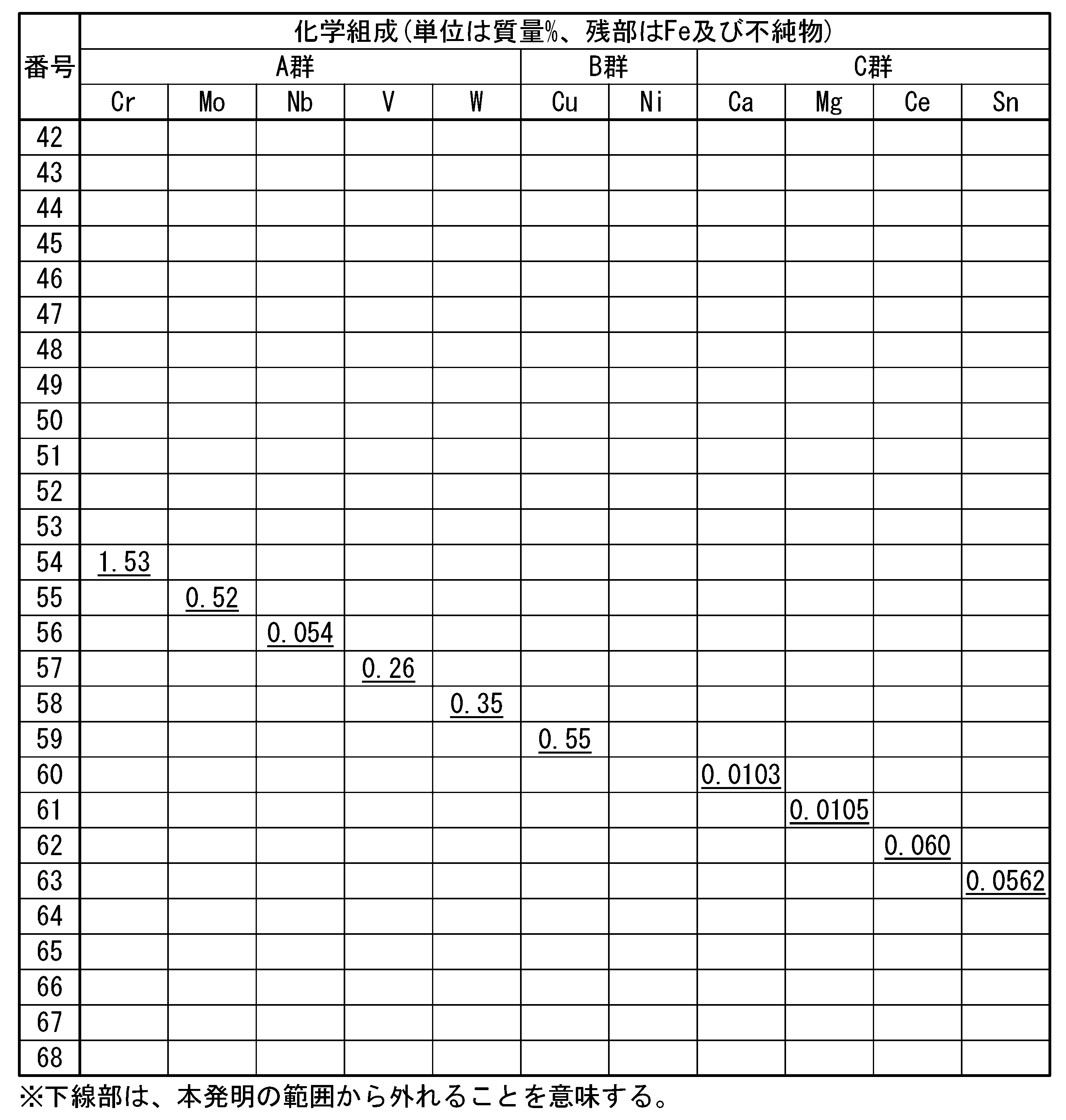


各水準のボルトについて、前述した方法により、D/4位置における硬質組織(ベイナイト組織)の面積率の測定、D/4位置における硬質組織(ベイナイト組織)以外の残部の確認、X線回折ピークの半価幅の測定、引張強さの測定、をそれぞれ行った。
各水準のボルトについて、フェライト相の(211)面に対応するX線回折ピークの半価幅の最大値βMAXとの比βMAX/βCを、前述した測定方法によって測定した。半価幅の算出には、X線回折装置(Rigaku AutoMATE)に付属するソフトウェアを用いた。
各水準のボルトについて、引張強さを、前述した測定方法によって測定した。引張試験時のクロスヘッド変位速度は3.0mm/minとした。
得られたボルトについて、以下の方法により、耐水素脆化特性を測定した。 ま
ず、ボルトを電界水素チャージすることにより、0.5ppmの拡散性水素をボルトに含有させた。電解水素チャージ方法は、ISO16573に準拠した。次に、試験中に水素が機械部品から大気中に放出することを防ぐために、試料にCdめっきを施した。次に、大気中で、そのボルトの最大引張荷重の90%の荷重をボルトに負荷し、この状態で100時間以上保持した。
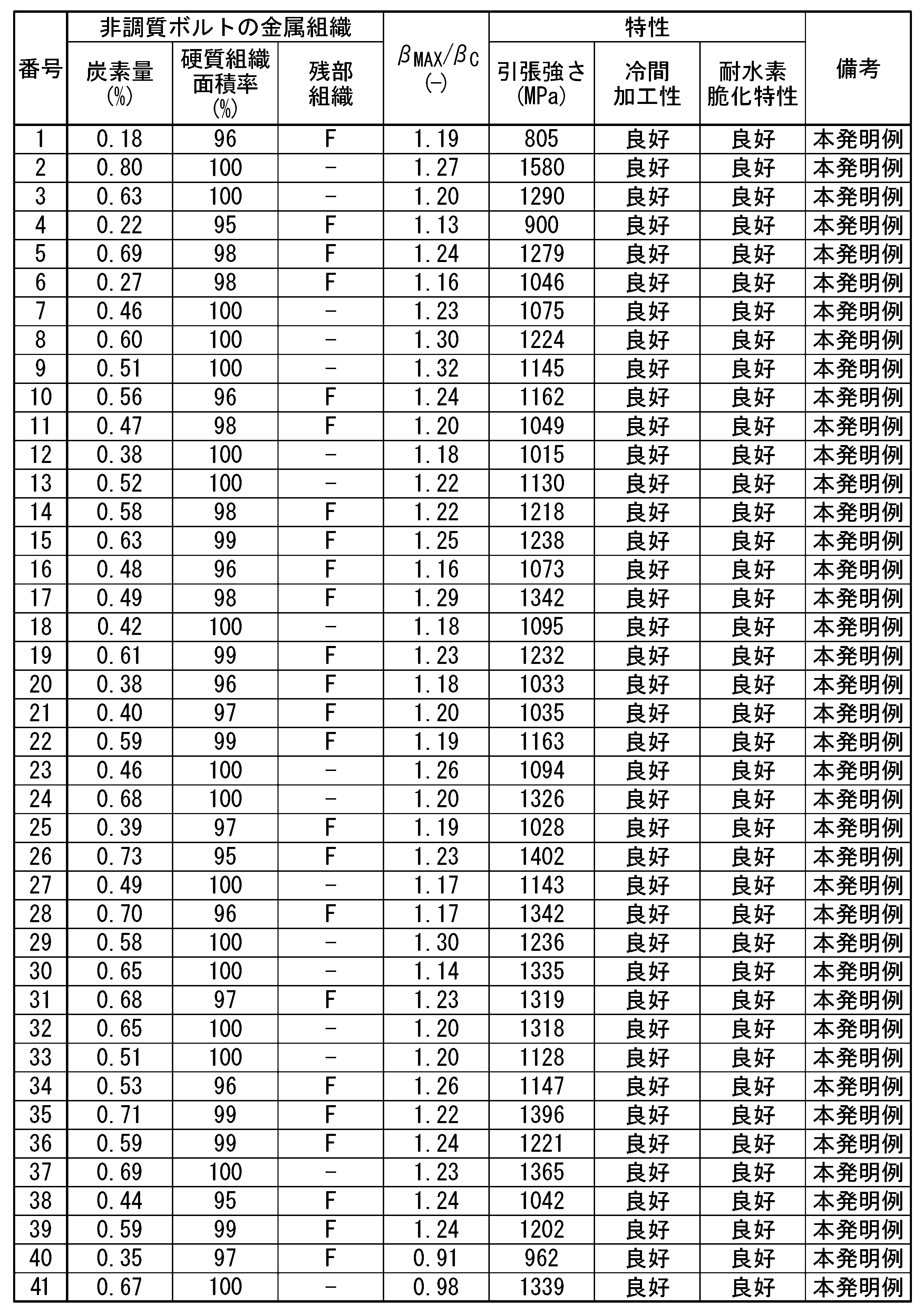

Claims (5)
- 化学組成が、質量%で、
C:0.18~0.80%、
Si:0.01~1.50%、
Mn:0.50~2.00%、
Al:0.005~0.080%、
P:0.030%以下、
S:0.030%以下、
Ti:0.005~0.100%、
B:0.0003~0.0050%、
N:0.0150%以下、
O:0.0100%以下、
残部:Fe及び不純物からなり、
軸部直径をDとして、D/4位置における金属組織の95%以上が硬質組織であり、
ボルト頭部と前記軸部との接続部の軸部中心におけるフェライト相の(211)面に対応するX線回折ピークの半価幅βCと、前記接続部の表面から軸部の中心軸線に向かう深さ500μmまでの領域におけるフェライト相の(211)面に対応するX線回折ピークの半価幅の最大値βMAXとの比βMAX/βCが1.50以下であり、
引張強さが800~1700MPaである、ボルト。 - 化学組成が、質量%で、
C:0.18~0.80%、
Si:0.01~1.50%、
Mn:0.50~2.00%、
Al:0.005~0.080%、
P:0.030%以下、
S:0.030%以下、
Ti:0.005~0.100%、
B:0.0003~0.0050%、
N:0.0150%以下、
O:0.0100%以下、を含有し、
更に、下記A群、B群及びC群からなる群から選択される1種又は2種以上を含有し、
残部:Fe及び不純物からなり、
軸部直径をDとして、D/4位置における金属組織の95%以上が硬質組織であり、
ボルト頭部と前記軸部との接続部の軸部中心におけるフェライト相の(211)面に対応するX線回折ピークの半価幅βCと、前記接続部の表面から軸部の中心軸線に向かう深さ500μmまでの領域におけるフェライト相の(211)面に対応するX線回折ピークの半価幅の最大値βMAXとの比βMAX/βCが1.50以下であり、
引張強さが800~1700MPaである、ボルト。
[A群]Cr:1.50%以下、Mo:0.50%以下、Nb:0.050%以下、V:0.20%以下、W:0.20%以下からなる群から選択される1種又は2種以上。
[B群]Cu:0.50%以下、Ni:0.50%以下からなる群から選択される1種又は2種。
[C群]Ca:0.0100%以下、Mg:0.0100%以下、Ce:0.020%以下、Sn:0.0400%以下からなる群から選択される1種又は2種以上。 - 質量%で、前記A群を含有する化学組成を有する請求項2に記載のボルト。
- 質量%で、前記B群を含有する化学組成を有する請求項2に記載のボルト。
- 質量%で、前記C群を含有する化学組成を有する請求項2に記載のボルト。
Priority Applications (3)
| Application Number | Priority Date | Filing Date | Title |
|---|---|---|---|
| JP2024539936A JP7773102B2 (ja) | 2023-03-15 | 2024-03-14 | ボルト |
| CN202480018283.4A CN120826486A (zh) | 2023-03-15 | 2024-03-14 | 螺栓 |
| KR1020257030859A KR20250149785A (ko) | 2023-03-15 | 2024-03-14 | 볼트 |
Applications Claiming Priority (2)
| Application Number | Priority Date | Filing Date | Title |
|---|---|---|---|
| JP2023041287 | 2023-03-15 | ||
| JP2023-041287 | 2023-03-15 |
Publications (1)
| Publication Number | Publication Date |
|---|---|
| WO2024190874A1 true WO2024190874A1 (ja) | 2024-09-19 |
Family
ID=92755980
Family Applications (1)
| Application Number | Title | Priority Date | Filing Date |
|---|---|---|---|
| PCT/JP2024/010018 Ceased WO2024190874A1 (ja) | 2023-03-15 | 2024-03-14 | ボルト |
Country Status (4)
| Country | Link |
|---|---|
| JP (1) | JP7773102B2 (ja) |
| KR (1) | KR20250149785A (ja) |
| CN (1) | CN120826486A (ja) |
| WO (1) | WO2024190874A1 (ja) |
Cited By (1)
| Publication number | Priority date | Publication date | Assignee | Title |
|---|---|---|---|---|
| CN119198524A (zh) * | 2024-11-26 | 2024-12-27 | 合肥通用机械研究院有限公司 | 高压气相氢致晶格畸变原位测试装置及原位测试方法 |
Citations (4)
| Publication number | Priority date | Publication date | Assignee | Title |
|---|---|---|---|---|
| WO2015083599A1 (ja) * | 2013-12-02 | 2015-06-11 | 株式会社神戸製鋼所 | ボルト用鋼線およびボルト、並びにそれらの製造方法 |
| WO2020090149A1 (ja) * | 2018-10-30 | 2020-05-07 | Jfeスチール株式会社 | ボルト用鋼及びその製造方法 |
| JP2021155816A (ja) * | 2020-03-27 | 2021-10-07 | 日本製鉄株式会社 | 鋼材 |
| JP2021183710A (ja) * | 2020-05-21 | 2021-12-02 | 日本製鉄株式会社 | 鋼線、非調質機械部品用線材、及び非調質機械部品 |
Family Cites Families (7)
| Publication number | Priority date | Publication date | Assignee | Title |
|---|---|---|---|---|
| JPH11315348A (ja) | 1998-04-30 | 1999-11-16 | Kobe Steel Ltd | 耐遅れ破壊性に優れた高強度線材およびその製造方法並びに高強度ボルト |
| JP3940270B2 (ja) | 2000-04-07 | 2007-07-04 | 本田技研工業株式会社 | 耐遅れ破壊性および耐リラクセーション特性に優れた高強度ボルトの製造方法 |
| JP4423219B2 (ja) | 2004-03-02 | 2010-03-03 | 本田技研工業株式会社 | 耐遅れ破壊特性及び耐リラクセーション特性に優れた高強度ボルト |
| JP4684862B2 (ja) | 2005-11-14 | 2011-05-18 | 株式会社神戸製鋼所 | ボルトの圧造方法 |
| WO2016121820A1 (ja) | 2015-01-27 | 2016-08-04 | 新日鐵住金株式会社 | 非調質機械部品用線材、非調質機械部品用鋼線、及び、非調質機械部品 |
| US20190024222A1 (en) | 2016-01-15 | 2019-01-24 | Nippon Steel & Sumitomo Metal Corporation | Steel wire for non-heat treated machine part and non-heat treated machine part |
| WO2022210125A1 (ja) * | 2021-03-31 | 2022-10-06 | 株式会社神戸製鋼所 | 機械構造部品用鋼線およびその製造方法 |
-
2024
- 2024-03-14 JP JP2024539936A patent/JP7773102B2/ja active Active
- 2024-03-14 WO PCT/JP2024/010018 patent/WO2024190874A1/ja not_active Ceased
- 2024-03-14 KR KR1020257030859A patent/KR20250149785A/ko active Pending
- 2024-03-14 CN CN202480018283.4A patent/CN120826486A/zh active Pending
Patent Citations (4)
| Publication number | Priority date | Publication date | Assignee | Title |
|---|---|---|---|---|
| WO2015083599A1 (ja) * | 2013-12-02 | 2015-06-11 | 株式会社神戸製鋼所 | ボルト用鋼線およびボルト、並びにそれらの製造方法 |
| WO2020090149A1 (ja) * | 2018-10-30 | 2020-05-07 | Jfeスチール株式会社 | ボルト用鋼及びその製造方法 |
| JP2021155816A (ja) * | 2020-03-27 | 2021-10-07 | 日本製鉄株式会社 | 鋼材 |
| JP2021183710A (ja) * | 2020-05-21 | 2021-12-02 | 日本製鉄株式会社 | 鋼線、非調質機械部品用線材、及び非調質機械部品 |
Cited By (1)
| Publication number | Priority date | Publication date | Assignee | Title |
|---|---|---|---|---|
| CN119198524A (zh) * | 2024-11-26 | 2024-12-27 | 合肥通用机械研究院有限公司 | 高压气相氢致晶格畸变原位测试装置及原位测试方法 |
Also Published As
| Publication number | Publication date |
|---|---|
| KR20250149785A (ko) | 2025-10-16 |
| JPWO2024190874A1 (ja) | 2024-09-19 |
| JP7773102B2 (ja) | 2025-11-19 |
| CN120826486A (zh) | 2025-10-21 |
Similar Documents
| Publication | Publication Date | Title |
|---|---|---|
| KR101961579B1 (ko) | 비조질 기계 부품용 선재, 비조질 기계 부품용 강선 및 비조질 기계 부품 | |
| JP3954338B2 (ja) | 耐ひずみ時効脆化特性および耐縦割れ性に優れる高強度鋼線およびその製造方法 | |
| EP2557191B1 (en) | Wire material for saw wire and method for producing same | |
| EP3135785B1 (en) | Spring steel and method for producing same | |
| JP6394708B2 (ja) | 伸線加工性に優れる高炭素鋼線材 | |
| JP6528860B2 (ja) | 非調質機械部品用鋼線及び非調質機械部品 | |
| RU2605033C1 (ru) | Низколегированная сталь для труб нефтепромыслового сортамента, имеющая превосходное сопротивление сульфидному растрескиванию под напряжением, и способ ее изготовления | |
| JP7518338B2 (ja) | 鋼線材 | |
| KR20220005094A (ko) | 고강도 열연 강판 및 그 제조 방법 | |
| JP6841383B2 (ja) | 鋼板及びその製造方法 | |
| KR20150023726A (ko) | 냉간 가공성, 피삭성 및 퀀칭성이 우수한 고탄소 강관 및 그 제조 방법 | |
| JP7469643B2 (ja) | 鋼線、非調質機械部品用線材、及び非調質機械部品 | |
| JPWO2017094870A1 (ja) | 冷間鍛造調質品用圧延棒線 | |
| JP6819198B2 (ja) | 冷間鍛造調質品用圧延棒線 | |
| JP6679935B2 (ja) | 冷間加工部品用鋼 | |
| JP7773102B2 (ja) | ボルト | |
| JP5679115B2 (ja) | 冷間加工性、被削性および焼入れ性に優れた高炭素鋼管およびその製造方法 | |
| JP3277878B2 (ja) | 伸線強化型高強度鋼線材およびその製造方法 | |
| CN108368583B (zh) | 非调质机械部件用钢丝及非调质机械部件 | |
| JP6645638B1 (ja) | ボルト用鋼 | |
| EP3385398A1 (en) | High-strength bolt | |
| JP2024131183A (ja) | 非調質ボルト | |
| JP7226083B2 (ja) | 線材及び鋼線 | |
| JP4915762B2 (ja) | 冷間加工性に優れた高強度鋼線又は棒鋼、高強度成形品並びにそれらの製造方法 | |
| JP2005320630A (ja) | 冷間加工性に優れた高強度鋼線又は棒鋼、高強度成形品並びにそれらの製造方法 |
Legal Events
| Date | Code | Title | Description |
|---|---|---|---|
| WWE | Wipo information: entry into national phase |
Ref document number: 2024539936 Country of ref document: JP |
|
| 121 | Ep: the epo has been informed by wipo that ep was designated in this application |
Ref document number: 24770977 Country of ref document: EP Kind code of ref document: A1 |
|
| WWE | Wipo information: entry into national phase |
Ref document number: 202517083785 Country of ref document: IN |
|
| WWE | Wipo information: entry into national phase |
Ref document number: 202480018283.4 Country of ref document: CN |
|
| ENP | Entry into the national phase |
Ref document number: 1020257030859 Country of ref document: KR Free format text: ST27 STATUS EVENT CODE: A-0-1-A10-A15-NAP-PA0105 (AS PROVIDED BY THE NATIONAL OFFICE) |
|
| WWP | Wipo information: published in national office |
Ref document number: 202517083785 Country of ref document: IN |
|
| NENP | Non-entry into the national phase |
Ref country code: DE |
|
| WWP | Wipo information: published in national office |
Ref document number: 1020257030859 Country of ref document: KR |
|
| WWP | Wipo information: published in national office |
Ref document number: 202480018283.4 Country of ref document: CN |
|
| 122 | Ep: pct application non-entry in european phase |
Ref document number: 24770977 Country of ref document: EP Kind code of ref document: A1 |