WO2024190643A1 - 測定装置 - Google Patents
測定装置 Download PDFInfo
- Publication number
- WO2024190643A1 WO2024190643A1 PCT/JP2024/008970 JP2024008970W WO2024190643A1 WO 2024190643 A1 WO2024190643 A1 WO 2024190643A1 JP 2024008970 W JP2024008970 W JP 2024008970W WO 2024190643 A1 WO2024190643 A1 WO 2024190643A1
- Authority
- WO
- WIPO (PCT)
- Prior art keywords
- temperature
- measurement
- stylus
- temperature correction
- detector
- Prior art date
- Legal status (The legal status is an assumption and is not a legal conclusion. Google has not performed a legal analysis and makes no representation as to the accuracy of the status listed.)
- Ceased
Links
Images




Classifications
-
- G—PHYSICS
- G01—MEASURING; TESTING
- G01B—MEASURING LENGTH, THICKNESS OR SIMILAR LINEAR DIMENSIONS; MEASURING ANGLES; MEASURING AREAS; MEASURING IRREGULARITIES OF SURFACES OR CONTOURS
- G01B5/00—Measuring arrangements characterised by the use of mechanical techniques
- G01B5/28—Measuring arrangements characterised by the use of mechanical techniques for measuring roughness or irregularity of surfaces
-
- G—PHYSICS
- G01—MEASURING; TESTING
- G01B—MEASURING LENGTH, THICKNESS OR SIMILAR LINEAR DIMENSIONS; MEASURING ANGLES; MEASURING AREAS; MEASURING IRREGULARITIES OF SURFACES OR CONTOURS
- G01B21/00—Measuring arrangements or details thereof, where the measuring technique is not covered by the other groups of this subclass, unspecified or not relevant
- G01B21/02—Measuring arrangements or details thereof, where the measuring technique is not covered by the other groups of this subclass, unspecified or not relevant for measuring length, width, or thickness
- G01B21/04—Measuring arrangements or details thereof, where the measuring technique is not covered by the other groups of this subclass, unspecified or not relevant for measuring length, width, or thickness by measuring coordinates of points
- G01B21/045—Correction of measurements
-
- G—PHYSICS
- G01—MEASURING; TESTING
- G01B—MEASURING LENGTH, THICKNESS OR SIMILAR LINEAR DIMENSIONS; MEASURING ANGLES; MEASURING AREAS; MEASURING IRREGULARITIES OF SURFACES OR CONTOURS
- G01B5/00—Measuring arrangements characterised by the use of mechanical techniques
- G01B5/0011—Arrangements for eliminating or compensation of measuring errors due to temperature or weight
- G01B5/0014—Arrangements for eliminating or compensation of measuring errors due to temperature or weight due to temperature
-
- G—PHYSICS
- G01—MEASURING; TESTING
- G01B—MEASURING LENGTH, THICKNESS OR SIMILAR LINEAR DIMENSIONS; MEASURING ANGLES; MEASURING AREAS; MEASURING IRREGULARITIES OF SURFACES OR CONTOURS
- G01B5/00—Measuring arrangements characterised by the use of mechanical techniques
- G01B5/20—Measuring arrangements characterised by the use of mechanical techniques for measuring contours or curvatures
-
- G—PHYSICS
- G01—MEASURING; TESTING
- G01B—MEASURING LENGTH, THICKNESS OR SIMILAR LINEAR DIMENSIONS; MEASURING ANGLES; MEASURING AREAS; MEASURING IRREGULARITIES OF SURFACES OR CONTOURS
- G01B2210/00—Aspects not specifically covered by any group under G01B, e.g. of wheel alignment, caliper-like sensors
- G01B2210/60—Unique sensor identification
Definitions
- the present invention relates to a measuring device, and in particular to a measuring device for measuring the shape, roughness, or contour of the surface of an object to be measured.
- Patent Document 1 discloses a surface quality measuring device that measures the surface quality of the measurement object's surface by scanning a stylus protruding from the tip of a measurement arm while it is in contact with the measurement object's surface and detecting minute up and down movements of the stylus.
- the measurement arm is supported so that it can swing (move in an arc) in the vertical direction around a rotation axis as a fulcrum.
- the rotation angle caused by the swinging of the measurement arm is detected using a scale with scale graduations along the swinging direction of the measurement arm.
- Patent Document 2 discloses that the thermal expansion coefficients of the stylus, scale, and connection parts of the measuring device are adjusted to satisfy certain conditions, thereby suppressing the effect of environmental temperature on the measurement results. Patent Document 2 also discloses that the thermal expansion coefficient of the stylus is adjusted to satisfy the above conditions by forming the stylus by joining together multiple members made of materials with different thermal expansion coefficients.
- a long stylus part is used in a measuring device with replaceable stylus to expand the measurement range by widening the movable range of the stylus tip.
- the measurement pressure applied to the stylus tip increases, which may cause wear on the stylus tip and scratches on the object being measured.
- the material constituting the stylus part is limited, it becomes difficult to adjust the thermal expansion coefficient of the stylus part by connecting multiple components together, as in Patent Document 2.
- the present invention was made in consideration of these circumstances, and aims to provide a measuring device that can suppress the effect of environmental temperature on the measurement results even when some of the components (measuring parts) of the measuring device, such as the stylus part or detector, are replaced.
- the measuring device is provided with a stylus for measuring the surface of the object to be measured, and is equipped with a detector including a stylus part mounted so as to be swingable around a swing center according to the shape of the surface of the object to be measured, a thermometer for measuring the temperature during measurement by the stylus part, a temperature correction parameter storage unit for storing temperature correction parameters according to the type of stylus part and the temperature during measurement measured by the thermometer and the temperature during calibration, and a temperature correction unit for detecting the type of stylus part used in the measurement, obtaining from the temperature correction parameter storage unit the temperature correction parameters according to the type of stylus part and the temperature during measurement measured by the thermometer and the temperature during calibration, and correcting the measurement result based on the temperature correction parameters.
- a detector including a stylus part mounted so as to be swingable around a swing center according to the shape of the surface of the object to be measured, a thermometer for measuring the temperature during measurement by the stylus part, a temperature correction parameter storage unit for storing temperature correction parameters according to the type
- the temperature correction parameter storage unit stores temperature correction parameters according to the type of detector, the temperature measured by the thermometer at the time of measurement, and the temperature measured at the time of calibration, and the temperature correction unit detects the type of detector used in the measurement, obtains the temperature correction parameters according to the type of detector, the temperature measured by the thermometer at the time of measurement, and the temperature measured at the time of calibration from the temperature correction parameter storage unit, and corrects the measurement results based on the temperature correction parameters.
- the measuring device is the first or second aspect, in which the temperature correction unit calculates the amount of thermal expansion of the calibrator based on the temperature measured by the thermometer when the stylus unit measures the calibrator to calibrate the measuring device, and corrects the measurement result based on the amount of thermal expansion.
- the effect of the environmental temperature on the measurement results can be suppressed.
- FIG. 1 is a diagram showing a measurement device according to an embodiment of the present invention.
- 2 is a block diagram showing a control system of the measurement device according to the embodiment of the present invention.
- FIG. 4 is a flow chart showing an overall flow of temperature correction.
- FIG. 13 is a diagram showing a measurement device during calibration.
- FIG. 2 is an enlarged side view of the calibrator.
- 11 is a diagram for explaining the influence of temperature changes in a measurement unit.
- FIG. 13 is a graph showing an example of calculation results of an error in the detector (Z-axis) indication precision.
- FIG. 13 is a diagram illustrating an example of temperature correction.
- FIG. 13 is a diagram showing an example of a GUI for temperature correction.
- 4 is a flowchart showing a procedure for calibrating the measurement device. 4 is a flowchart showing a procedure for measuring a measurement target W in the measuring device.
- Measurement device 1 is a diagram showing a measurement device according to an embodiment of the present invention.
- a three-dimensional orthogonal coordinate system is used in which the XY plane is the horizontal plane and the Z direction is the vertical direction (perpendicular direction).
- the measuring device 1 is a device for measuring the shape, roughness, contour, etc. of the surface of a measuring object W placed on a measuring object placement section (hereinafter referred to as a stage) 50.
- the stage 50 is placed on a base plate 52, and the surface of the stage 50 (the surface on which the measurement target W is placed) is parallel to the XY plane.
- a column (Z-axis) 54 extending approximately perpendicular to the surface of the stage 50 is placed on the base plate 52.
- a carriage (X-axis) 56 is attached to the column 54, and the carriage 56 can be moved in the Z direction along the column 54 by an actuator (not shown).
- the detector 10 is attached to the carriage 56, and the detector 10 can be moved in the X direction relative to the carriage 56 by an actuator (not shown).
- a scale 58 for detecting the X direction position of the detector 10 is attached to the carriage 56.
- the scale 58 is, for example, a linear scale (linear position scale) with scale marks formed along its length.
- the detector 10 is movable with respect to the column 54, but the present invention is not limited to this.
- the column 54 may be movable along the X direction relative to the stage 50, or the stage 50 may be movable along the X or Z direction relative to the column 54.
- the measurement object W placed on the stage 50 and the detector 10 are configured to be relatively movable in the XZ directions.
- the detector 10 may also be movable relative to the measurement object W placed on the stage 50 in the Y direction as well as the X direction.
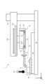
- the detector 10 includes a stylus portion 14, an arm portion 16, a pivot shaft 20, a scale 22, and a scale head 24.
- the probe portion 14 is fixed so as to be in approximately a straight line with the arm portion 16, and the probe portion 14 and the arm portion 16 are attached to the detector housing 26 so as to be able to swing integrally around the swing axis 20.
- the mounting angle with respect to the carriage 56 of the detector 10 is adjusted so that the swing axis 20 is approximately parallel to the XY plane.
- the probe portion 14 attached to the arm portion 16 is also referred to as the swing portion 18.
- the configuration of the oscillating portion 18 is not limited to the substantially linear example shown in FIG. 1.
- the probe portion 14 or the arm portion 16 may have an L-shaped bent portion, and the probe portion 14 and the arm portion 16 may be attached so as to be substantially parallel.
- a stylus 12 is provided at the tip of the stylus portion 14.
- the stylus 12 extends downward (in the -Z direction) in the figure.
- the oscillating portion 18 oscillates around the oscillating axis 20 according to the height and unevenness of the surface of the measurement object W at the contact position.
- the configuration of the stylus portion 14 is not limited to the example shown in FIG. 1.
- the stylus portion 14 may be a T-shaped stylus with styluses provided in the vertical direction in the figure, or an L-shaped stylus with a stylus protruding downward in the figure longer than the example shown in FIG. 1.
- the scale 22 is fixed to the detector housing 26 so as to face the base end of the arm portion 16.
- the detector housing 26 is a member that connects the oscillation center 20C of the oscillation shaft 20 and the scale 22 (defines the distance between the oscillation center 20C of the oscillation shaft 20 and the scale 22).
- the scale 22 is, for example, a linear scale (linear position scale) with scale graduations formed along the length of the scale 22.
- the scale 22 is attached so that its length (displacement detection direction) is approximately perpendicular to the length of the oscillating portion 18.
- the scale head 24 is fixed to the base end of the arm portion 16 and can swing integrally with the swinging portion 18.
- the scale head 24 is a device that reads the scale (hereinafter referred to as the indicated value) at the opposing position of the scale 22 fixed to the detector housing 26.
- the type of the scale head 24 is not particularly limited, but the scale head 24 can be, for example, a photoelectric sensor for reading the scale of the scale 22 or a non-contact sensor equipped with an imaging element and an illumination light source (for example, an LED (Light-Emitting Diode)).
- the reading of the scale 22 read by the scale head 24 is output to the control device 100 (see Figure 2).
- the control device 100 controls the actuators provided on the column 54 and carriage 56 to move the measurement object W and the stylus 12 of the detector 10 relative to each other, while obtaining readings of the graduations on the scale 22 for each position on the surface of the measurement object W. This makes it possible to measure the shape, roughness, contour, etc. of the surface of the measurement object W.
- the scale 22 is fixed to the detector housing 26, and the scale head 24 is fixed to the base end of the arm portion 16, but the present invention is not limited to this.
- the scale head 24 may be fixed to the detector housing 26, and the scale 22 may be fixed to the base end of the arm portion 16.
- the scale 22 is not limited to a linear scale, and may be, for example, an arc scale (angle scale) formed in an arc shape along the swing direction of the arm portion 16.
- FIG. 2 is a block diagram showing the control system of the measuring device 1.
- the control device 100 includes a control unit 102, an input unit 104, and a display unit 106.
- the control unit 102 includes a processor (e.g., a CPU (Central Processing Unit) or MPU (Micro-Processing Unit)) for controlling each part of the measuring device 1, and a memory (e.g., a ROM (Read Only Memory), RAM (Random Access Memory)).
- a processor e.g., a CPU (Central Processing Unit) or MPU (Micro-Processing Unit)
- a memory e.g., a ROM (Read Only Memory), RAM (Random Access Memory)
- the control unit 102 In response to operation input from the input unit 104, the control unit 102 outputs control signals for controlling the control device 100 and the measuring device 1, and control signals for controlling actuators for moving the detector 10, etc.
- the control unit 102 has a function of detecting the type of the measurement unit when a part of a component (measurement unit) of the measurement device 1, such as the stylus unit 14 or the detector 10, is replaced, and a temperature correction function based on the type of the measurement unit and the temperatures at the time of calibration and measurement.
- the control unit 102 is an example of a temperature correction unit.
- the input unit 104 is a device for accepting operational input from an operator, and includes, for example, a keyboard, a mouse, a touch panel, etc.
- the display unit 106 is a device for displaying images, and includes, for example, an LCD (Liquid Crystal Display).
- the display unit 106 displays, for example, a GUI (Graphical User Interface) for operating the control device 100, the measuring device 1, the actuator, etc., and measurement results such as the shape, roughness, or contour of the surface of the measurement object W.
- GUI Graphic User Interface
- Storage 108 is a device that stores programs for controlling the measuring device 1 and measurement result data, and includes, for example, an HDD (Hard Disk Drive) or an SSD (Solid State Drive).
- Storage 108 is an example of a temperature correction parameter storage unit that stores the temperature correction parameters described below.
- the detector drive mechanism 60 includes an X-axis drive section and a Z-axis drive section (e.g., actuators, not shown in FIG. 1) for moving the detector 10 in the X and Z directions, respectively.
- a Z-axis drive section e.g., actuators, not shown in FIG. 1
- the thermometer 80 is a thermometer capable of measuring the environmental temperature in the vicinity of the stage 50.
- the thermometer 80 is placed in the vicinity of the stage 50, but the location of the thermometer 80 is not particularly limited.
- the temperature of a drive unit such as the detector drive mechanism 60.
- the thermometer 80 may be, for example, a radiation temperature sensor or a color temperature sensor for measuring the temperature of the measurement object W, the calibrator M (see FIG. 4), or the detector 10.
- the control unit 102 accepts input of the readings of the scale 22 from the scale head 24, and calculates the shape, roughness, contour, etc. of the surface of the measurement object W from the readings of the scale 22.
- control unit 102 performs temperature correction (described below) based on temperatures T1 and T2 measured by the thermometer 80 when calibrating the measurement device 1 and when measuring the measurement object W, respectively.
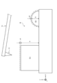
- Fig. 4 is a diagram showing the measuring device 1 during calibration. As shown in Fig. 4, during calibration, a calibrator (master) M is placed on the stage 50 of the measuring device 1. During calibration, temperature correction is performed taking into account the effect of temperature change (amount of thermal expansion) in the calibrator M, as described below.
- FIG. 5 is an enlarged side view of the calibrator M.
- a rectangular block gauge G1 and a hemispherical ball G2 are formed on the upper part of the base part of the calibrator M.
- Parameters indicating the surface shape of the calibrator M at a reference temperature T0 (20°C in one example), i.e., the height H of the block gauge G1 (height from the base surface of the calibrator M) and the radius R of the ball G2 at the reference temperature T0, are known.
- the calibrator M expands as shown in Figure 5.
- the height of the block gauge G1 at temperature T1 is H + ⁇ H, and the radius of the ball G2 is R + ⁇ R.
- the thermal expansion coefficient of the block gauge G1 is ⁇ and the thermal expansion coefficient of the ball G2 is ⁇ , the height of the block gauge G1 and the radius of the ball G2 at temperature T1 are expressed by the following formula.
- the thermal expansion coefficient ⁇ of the block gauge G1 and the thermal expansion coefficient ⁇ of the ball G2 are known values determined according to the material and shape of the calibrator M. Therefore, the height of the block gauge G1 and the radius of the ball G2 at the time of calibration can be calculated from the difference ⁇ T between the temperature (environmental temperature) T1 measured by the thermometer 80 at the time of calibration and the reference temperature T0.
- Fig. 6 is a diagram for explaining the influence of temperature change of the measurement part.
- the oscillating part 18 (the stylus part 14 and the arm part 16) at the calibration temperature T1 and the measurement temperature T2 are simplified and shown by solid and dashed straight lines, respectively, and the stylus 12 is omitted because it is short compared to the length of the oscillating part 18 and can be ignored.
- the distance from the tip of the probe portion 14 to the oscillation center 20C at the reference temperature T0 is L1
- the distance from the oscillation center 20C to the base end of the arm portion 16 is L2.
- the indicated value of the scale 22 at the measurement height Z is Z2. Note that the connection between the probe portion 14 and the arm portion 16 is omitted in Figure 6, but as shown in Figure 1, the distance L1 corresponds to the sum of the length of the probe portion 14 and the length of the portion from the tip of the arm portion 16 to the oscillation center 20C
- the distance L2 corresponds to the sum of the length of the portion from the oscillation center 20C to the base end of the arm portion 16.
- the oscillating part 18 expands as shown by the dashed line in Figure 6.
- the distance from the stylus part 14 to the oscillating center 20C at temperature T2 after the temperature expansion is L1a, and the distance from the oscillating center 20C to the base end of the arm part 16 is L2a.
- the indication value Z2a at the measurement height Z in the measuring device 1 after the temperature expansion is expressed by the following formula.
- Z2a Z2 ⁇ C...(3)
- the distances L1 and L2 at the calibration temperature T1 are known, and the distances L1a and L2a at the temperature T2 depend on the material and shape of the stylus portion 14 and the arm portion 16, as in the case of the formulas (1) and (2). It can be calculated from the thermal expansion coefficients of the probe portion 14 and the arm portion 16, which are determined according to the above factors, and the temperature difference ⁇ T.
- constant C is a value determined by the type of stylus portion 14 and arm portion 16 or detector 10 and the difference T2-T1 between the temperature at the time of calibration and the temperature at the time of measurement.
- Constant C is stored in storage 108 as a temperature correction parameter (temperature correction coefficient) in association with information about the components of the measuring device 1 used in the measurement (e.g., the type of stylus portion 14 or detector 10).
- Figure 7 is a graph showing an example of the calculation results for the error in the detector (Z-axis) indication accuracy.
- the horizontal axis of Figure 7 indicates the stylus stroke (stroke position Z2 at reference temperature T1), and the vertical axis indicates the detector (Z-axis) indication accuracy (Z2a-Z2).
- Figure 7 shows a graph of the calculation results when the temperature changes by ⁇ 10°C from the calibration temperature T1, and the slope of each graph (C-1) corresponds to the temperature correction parameter C.
- temperature correction is performed using a temperature correction parameter C prepared for each type of stylus part 14 or detector 10, so that the detector indication accuracy (Z2a-Z2) becomes zero. This makes it possible to suppress the effect of the environmental temperature on the measurement results.
- the temperature correction parameter C used during measurement may be stored as a table (lookup table) corresponding to the temperature T1 at the time of calibration and the temperature T2 at the time of measurement, or may be stored as a function calculated from the temperature correction parameter C corresponding to the temperature T1 at the time of calibration and the temperature T2 at the time of measurement (for example, an approximation curve calculated by least squares approximation or polynomial approximation, etc.).
- the temperature correction parameter C is stored as a table, it is possible to obtain the temperature correction parameter C corresponding to any temperature T1 and T2 by performing an interpolation calculation, an internal interpolation or an extrapolation based on the temperature T1 at the time of calibration and the temperature T2 at the time of measurement.
- the temperature correction parameter C can be obtained from storage 108 to correct the measurement results of the object W.
- the measuring device 1 is a device in which the stylus part 14, i.e. the part from the fixed part fixed to the arm part 16 to the stylus 12 at the tip, is removable and replaceable.
- the control part 102 has a function of acquiring information for identifying the stylus part 14 (e.g., an ID (identifier)) or information regarding the type of the stylus part 14 (e.g., the length or material of the arm, etc.).
- Specific modes for acquiring information regarding the type of the stylus part 14 include, for example, the following (1-1) or (1-2).
- a unique ID (for example, an identification code) is given to the probe portion 14, and a table of temperature correction parameters unique to each probe portion 14 is provided on the measurement device 1 side (in the storage 108).
- the stylus portion 14 is provided with information on its length and material, and the measuring device 1 (control portion 102) is provided with a function for calculating temperature correction parameters.
- the measuring device 1 is a device in which the detector 10 can be detached and replaced from the carriage 56 and the detector driving mechanism 60.
- the control unit 102 has a function of acquiring information for identifying the detector 10 (e.g., an ID (identifier)) or information regarding the type of the detector 10 (e.g., the length or material of an arm provided on the detector 10).
- Specific modes for acquiring information regarding the type of the detector 10 include, for example, any of the following (2-1) to (2-3).
- a unique ID (for example, an identification code) is given to the detector 10, and a table of temperature correction parameters unique to each detector 10 is provided on the measurement device 1 side (in the storage 108).
- the detector 10 is provided with information regarding the length or material of its internal arm, and the measuring device 1 (control unit 102) is provided with a function for calculating temperature correction parameters. (2-3) It has the function of calculating a temperature correction parameter from a combination of the ID of the stylus part 14 and the ID of the detector 10.
- the means by which the control unit 102 detects the type of the stylus unit 14 or the detector 10 may be, for example, a user inputting an ID from the input unit 104, or the ID of the stylus unit 14 or the detector 10 may be stored in a two-dimensional code or a non-contact tag (for example, an IC (Integrated Circuit) tag or an RFID (Radio Frequency Identification) tag) and read by the control device 100.
- a non-contact tag for example, an IC (Integrated Circuit) tag or an RFID (Radio Frequency Identification) tag
- FIG. 9 is a diagram showing an example of a GUI for temperature correction.
- the temperature (ambient temperature) measured by the thermometer 80 at the time of calibration and measurement can be input.
- a check box can be used to select whether or not to use the temperature of a driving part such as the detector driving mechanism 60 for temperature correction during measurement.
- These values may be input manually using the input unit 104, or may be automatically input by the control unit 102 acquiring the values from the thermometer 80 or the thermometer of the driving part.
- the thermal expansion coefficients of the block gauge G1, ball G2, and stylus portion 14 can be input. These values may be input manually using the input unit 104, or the thermal expansion coefficients ⁇ and ⁇ corresponding to the block gauge G1 and ball G2 of the calibrator M may be stored in advance in the storage 108, and the values read out by the control unit 102 during calibration may be automatically input. This makes it possible to easily perform temperature correction.
- the user can select whether or not to perform temperature correction of the calibrator M and the stylus part 14 by using a check box.
- FIG. 10 is a flowchart showing the procedure for calibrating the measurement device 1.
- the calibrator M is placed on the stage 50 of the measuring device 1 (step S10).
- control unit 102 acquires information about the measurement unit (e.g., the type of stylus unit 14 or detector 10) attached to the measurement device 1 (step S12).
- the measurement unit e.g., the type of stylus unit 14 or detector
- the measurement device 1 measures the surface shape of the calibrator M (step S14).
- the control unit 102 acquires the measurement results of the surface shape of the calibrator M and the temperature T1 at the time of calibration measured by the thermometer 80 (step S16).
- control unit 102 calculates the amount of thermal expansion of the calibrator M at the time of calibration based on the type information of the measurement unit and the temperature T1 at the time of calibration (step S18). Then, the control unit 102 corrects the measurement results of the calibrator M using the amount of thermal expansion of the calibrator M and stores them (step S20).
- step S20 the control unit 102 first calculates the dimensions of the calibrator M after thermal expansion, i.e., the height H+ ⁇ H of the block gauge G1 and the radius R+ ⁇ R of the ball G2. The control unit 102 then calculates the distances L1 and L2 using the height H+ ⁇ H of the block gauge G1 and the radius R+ ⁇ R of the ball G2. This allows temperature correction of the calibration of the measurement device 1.
- the measurement results of the calibrator M can be corrected by calculating the dimensions of the calibrator M after thermal expansion according to the temperature T1 at the time of calibration measured by the thermometer 80.
- FIG. 11 is a flowchart showing the procedure for measuring the object W to be measured using the measuring device 1.
- the measurement object W is placed on the stage 50 of the measurement device 1 (step S30).
- control unit 102 acquires information about the measurement unit (e.g., the type of stylus unit 14 or detector 10) attached to the measurement device 1 (step S32).
- the measurement unit e.g., the type of stylus unit 14 or detector
- the measurement device 1 measures the surface shape of the measurement object W (step S34).
- the control unit 102 acquires the measurement result of the surface shape of the measurement object W and the temperature T2 at the time of measurement measured by the thermometer 80 (step S36).
- control unit 102 acquires a temperature correction parameter from the storage 108 based on the type information of the measurement unit, the temperature T1 at the time of calibration, and the temperature T2 at the time of measurement (step S38), and corrects and stores the measurement results of the measurement object W using the temperature correction parameter (step S40).
- step S40 the temperature correction coefficient C and the indication value Z2a at temperature T2 are used to calculate the indication value Z2 that eliminates the effects of the temperature expansion of the stylus portion 14 (see formula (4)). This allows the measurement result of the measurement object W at temperature T2 to be obtained with high accuracy.
- the effect of the environmental temperature on the measurement results can be suppressed.
- 1...measuring device 10...detector, 12...probe, 14...probe section, 16...arm section, 18...oscillating section, 20...oscillating axis, 22...scale, 24...scale head, 26...detector housing, 50...measurement object placement section, 52...base plate, 54...column, 56...carriage, 58...scale, 60...detector drive mechanism, 80...thermometer, 100...control device, 102...control section, 104...input section, 106...display section, 108...storage
Landscapes
- Physics & Mathematics (AREA)
- General Physics & Mathematics (AREA)
- A Measuring Device Byusing Mechanical Method (AREA)
- Length Measuring Devices With Unspecified Measuring Means (AREA)
Abstract
Description
図1は、本発明の一実施形態に係る測定装置を示す図である。以下の説明では、XY平面を水平面とし、Z方向を垂直方向(鉛直方向)とする3次元直交座標系を用いる。
測定装置1により測定対象物Wの測定を行う場合には、測定装置1の精度を確認等のための校正を行う。図4は、校正時の測定装置1を示す図である。図4に示すように、校正時には、測定装置1のステージ50に校正器(マスター)Mを設置する。校正時には、下記の通り、校正器Mにおける温度変化の影響(熱膨張量)を考慮して温度補正を行う。
図5は、校正器Mを拡大して示す側面図である。図5に示すように、校正器Mのベース部分の上部には、直方体状のブロックゲージG1と、半球状のボールG2が形成されている。基準温度T0(一例で20℃)における校正器Mの表面形状を示すパラメータ、すなわち、基準温度T0におけるブロックゲージG1の高さ(校正器Mのベース表面からの高さ)Hと、ボールG2の半径Rは既知となっている。
ボールG2の半径 : R+β*ΔT …(2)
ブロックゲージG1の熱膨張率αとボールG2の熱膨張率βは、校正器Mの材質及び形状等に応じて決まる既知の値である。したがって、温度計80により校正時に測定した温度(環境温度)T1と基準温度T0の差分ΔTから、校正時のブロックゲージG1の高さとボールG2の半径とを算出することができる。
図6は、測定部の温度変化の影響を説明するための図である。図6では、校正時温度T1と測定時の温度T2における揺動部18(触針部14及びアーム部16)を、それぞれ実線と破線の直線により簡略化して示しており、触針12は、揺動部18の長さと比較して短く無視することができるので省略している。
上記の式より、測定高さZが同じ場合、温度膨張後の温度T2における指示値Z2aは、校正時温度T1における指示値Z2に比例する。したがって、温度膨張後の指示値Z2aは、定数Cを用いて下記の式(3)により表すことができる。
ここで、校正時温度T1における距離L1及びL2は既知であり、温度T2における距離L1a及びL2aは、式(1)及び式(2)と同様、触針部14及びアーム部16の材質及び形状等に応じて決まる触針部14及びアーム部16の熱膨張率と温度の差分ΔTから算出することができる。
実施例1に係る測定装置1は、触針部14、すなわち、アーム部16に固定される固定部から先端の触針12までの部分を取り外して交換可能な装置である。実施例1では、制御部102は、触針部14を特定するための情報(例えば、ID(identifier))、又は触針部14の種類(例えば、アームの長さ又は材質等)に関する情報を取得する機能を有する。触針部14の種類に関する情報の取得のための具体的な態様としては、例えば、下記の(1-1)又は(1-2)が考えられる。
(1-1)触針部14に固有のID(例えば、識別符号)を持たせ、測定装置1側(ストレージ108内)に触針部14ごとに固有の温度補正パラメータのテーブルを持たせる。
(1-2)触針部14にその長さ及び材質情報を持たせ、測定装置1側(制御部102)に温度補正パラメータを演算する機能を持たせる。
実施例2に係る測定装置1は、キャリッジ56及び検出器駆動機構60から検出器10を取り外して交換可能な装置である。実施例2では、制御部102は、検出器10を特定するための情報(例えば、ID(identifier))、又は検出器10の種類(例えば、検出器10に設けられたアームの長さ又は材質等)に関する情報を取得する機能を有する。検出器10の種類に関する情報の取得のための具体的な態様としては、例えば、下記の(2-1)から(2-3)のいずれかが考えられる。
(2-1)検出器10に固有のID(例えば、識別符号)を持たせ、測定装置1側(ストレージ108内)に検出器10ごとに固有の温度補正パラメータのテーブルを持たせる。
(2-2)検出器10にその内部のアームの長さ又は材質等に関する情報を持たせ、測定装置1側(制御部102)に温度補正パラメータを演算する機能を持たせる。
(2-3)触針部14のIDと検出器10のIDの組合せから温度補正パラメータを演算する機能を持たせる。
図10は、測定装置1の校正の手順を示すフローチャートである。
Claims (3)
- 測定対象物の表面の測定を行うための触針が設けられており、前記測定対象物の表面の形状に応じて揺動中心の周りに揺動可能に取り付けられた触針部を含む検出器と、
前記触針部による測定時の温度を測定する温度計と、
前記触針部の種類と、前記温度計により測定した測定時の温度と校正時の温度に応じた温度補正パラメータを保持する温度補正パラメータ保持部と、
前記測定に使用した前記触針部の種類を検出し、前記触針部の種類と、前記温度計により測定した測定時の温度と校正時の温度に応じた温度補正パラメータを前記温度補正パラメータ保持部から取得し、前記温度補正パラメータに基づいて前記測定の結果を補正する温度補正部と、
を備える測定装置。 - 前記温度補正パラメータ保持部は、前記検出器の種類と、前記温度計により測定した測定時の温度と校正時の温度に応じた温度補正パラメータを保持し、
前記温度補正部は、前記測定に使用した前記検出器の種類を検出し、前記検出器の種類と、前記温度計により測定した測定時の温度と校正時の温度に応じた温度補正パラメータを前記温度補正パラメータ保持部から取得し、前記温度補正パラメータに基づいて前記測定の結果を補正する、請求項1に記載の測定装置。 - 前記温度補正部は、前記触針部により、前記測定装置の校正を行うための校正器の測定を行う際に、前記温度計により測定した温度に基づいて前記校正器の熱膨張量を算出し、前記熱膨張量に基づいて前記測定の結果を補正する、請求項1又は2に記載の測定装置。
Priority Applications (2)
| Application Number | Priority Date | Filing Date | Title |
|---|---|---|---|
| DE112024001199.3T DE112024001199T5 (de) | 2023-03-13 | 2024-03-08 | Messvorrichtung |
| CN202480018515.6A CN120898109A (zh) | 2023-03-13 | 2024-03-08 | 测定装置 |
Applications Claiming Priority (2)
| Application Number | Priority Date | Filing Date | Title |
|---|---|---|---|
| JP2023-039048 | 2023-03-13 | ||
| JP2023039048A JP2024129692A (ja) | 2023-03-13 | 2023-03-13 | 測定装置 |
Publications (1)
| Publication Number | Publication Date |
|---|---|
| WO2024190643A1 true WO2024190643A1 (ja) | 2024-09-19 |
Family
ID=92755703
Family Applications (1)
| Application Number | Title | Priority Date | Filing Date |
|---|---|---|---|
| PCT/JP2024/008970 Ceased WO2024190643A1 (ja) | 2023-03-13 | 2024-03-08 | 測定装置 |
Country Status (4)
| Country | Link |
|---|---|
| JP (1) | JP2024129692A (ja) |
| CN (1) | CN120898109A (ja) |
| DE (1) | DE112024001199T5 (ja) |
| WO (1) | WO2024190643A1 (ja) |
Families Citing this family (1)
| Publication number | Priority date | Publication date | Assignee | Title |
|---|---|---|---|---|
| CN120651078B (zh) * | 2025-07-24 | 2025-11-18 | 中国电子产品可靠性与环境试验研究所((工业和信息化部电子第五研究所)(中国赛宝实验室)) | 一种光面环规自动校准装置和方法 |
Citations (3)
| Publication number | Priority date | Publication date | Assignee | Title |
|---|---|---|---|---|
| JPS60214212A (ja) * | 1984-04-10 | 1985-10-26 | Mitsutoyo Mfg Co Ltd | 測定装置 |
| JPH0327305U (ja) * | 1988-11-05 | 1991-03-19 | ||
| WO2021220595A1 (ja) * | 2020-04-30 | 2021-11-04 | 株式会社東京精密 | 測定装置 |
-
2023
- 2023-03-13 JP JP2023039048A patent/JP2024129692A/ja active Pending
-
2024
- 2024-03-08 DE DE112024001199.3T patent/DE112024001199T5/de active Pending
- 2024-03-08 CN CN202480018515.6A patent/CN120898109A/zh active Pending
- 2024-03-08 WO PCT/JP2024/008970 patent/WO2024190643A1/ja not_active Ceased
Patent Citations (3)
| Publication number | Priority date | Publication date | Assignee | Title |
|---|---|---|---|---|
| JPS60214212A (ja) * | 1984-04-10 | 1985-10-26 | Mitsutoyo Mfg Co Ltd | 測定装置 |
| JPH0327305U (ja) * | 1988-11-05 | 1991-03-19 | ||
| WO2021220595A1 (ja) * | 2020-04-30 | 2021-11-04 | 株式会社東京精密 | 測定装置 |
Also Published As
| Publication number | Publication date |
|---|---|
| DE112024001199T5 (de) | 2026-01-15 |
| JP2024129692A (ja) | 2024-09-27 |
| CN120898109A (zh) | 2025-11-04 |
Similar Documents
| Publication | Publication Date | Title |
|---|---|---|
| US11859969B2 (en) | Measurement device | |
| JP6324588B2 (ja) | 輪郭形状表面粗さ測定装置および輪郭形状表面粗さ測定方法 | |
| JP5845373B2 (ja) | 形状測定・校正装置 | |
| JP4776473B2 (ja) | 光軸偏向型レーザ干渉計、その校正方法、補正方法、及び、測定方法 | |
| WO2024190643A1 (ja) | 測定装置 | |
| JP4931867B2 (ja) | 可変端度器 | |
| TWI904630B (zh) | 雷射測量校正方法 | |
| WO2024190644A1 (ja) | 測定装置 | |
| JP2024129693A (ja) | 測定装置 | |
| JP2024129694A (ja) | 測定装置 | |
| WO2026004716A1 (ja) | 校正方法及び校正装置 | |
| JP2026006943A (ja) | 測定装置、測定方法及び測定制御プログラム | |
| JP2004108959A (ja) | 形状測定装置 | |
| JP7781368B2 (ja) | 形状測定装置の調整方法 | |
| JP2003114116A (ja) | 倣いプローブの校正装置および校正方法および誤差補正方法 | |
| JP2026006945A (ja) | 測定装置、測定方法及び測定制御プログラム | |
| WO2026009786A1 (ja) | 測定装置、測定方法及び測定制御プログラム | |
| JP2010169635A (ja) | 形状測定装置 | |
| JP2021173719A (ja) | 測定装置 | |
| Mahammad | Improvements of the Calibration of the Electronic Level by a New Multiple Reflections Technique Based Setup |
Legal Events
| Date | Code | Title | Description |
|---|---|---|---|
| 121 | Ep: the epo has been informed by wipo that ep was designated in this application |
Ref document number: 24770749 Country of ref document: EP Kind code of ref document: A1 |
|
| WWE | Wipo information: entry into national phase |
Ref document number: 202480018515.6 Country of ref document: CN |
|
| WWE | Wipo information: entry into national phase |
Ref document number: 202547095961 Country of ref document: IN |
|
| WWE | Wipo information: entry into national phase |
Ref document number: 112024001199 Country of ref document: DE |
|
| WWP | Wipo information: published in national office |
Ref document number: 202480018515.6 Country of ref document: CN |
|
| WWP | Wipo information: published in national office |
Ref document number: 202547095961 Country of ref document: IN |
|
| WWP | Wipo information: published in national office |
Ref document number: 112024001199 Country of ref document: DE |
|
| 122 | Ep: pct application non-entry in european phase |
Ref document number: 24770749 Country of ref document: EP Kind code of ref document: A1 |