WO2024190361A1 - 密封装置 - Google Patents
密封装置 Download PDFInfo
- Publication number
- WO2024190361A1 WO2024190361A1 PCT/JP2024/006531 JP2024006531W WO2024190361A1 WO 2024190361 A1 WO2024190361 A1 WO 2024190361A1 JP 2024006531 W JP2024006531 W JP 2024006531W WO 2024190361 A1 WO2024190361 A1 WO 2024190361A1
- Authority
- WO
- WIPO (PCT)
- Prior art keywords
- lip
- sealing device
- inward
- conductive
- rotating shaft
- Prior art date
- Legal status (The legal status is an assumption and is not a legal conclusion. Google has not performed a legal analysis and makes no representation as to the accuracy of the status listed.)
- Ceased
Links
Images


Classifications
-
- F—MECHANICAL ENGINEERING; LIGHTING; HEATING; WEAPONS; BLASTING
- F16—ENGINEERING ELEMENTS AND UNITS; GENERAL MEASURES FOR PRODUCING AND MAINTAINING EFFECTIVE FUNCTIONING OF MACHINES OR INSTALLATIONS; THERMAL INSULATION IN GENERAL
- F16J—PISTONS; CYLINDERS; SEALINGS
- F16J15/00—Sealings
- F16J15/16—Sealings between relatively-moving surfaces
- F16J15/32—Sealings between relatively-moving surfaces with elastic sealings, e.g. O-rings
- F16J15/3284—Sealings between relatively-moving surfaces with elastic sealings, e.g. O-rings characterised by their structure; Selection of materials
-
- F—MECHANICAL ENGINEERING; LIGHTING; HEATING; WEAPONS; BLASTING
- F16—ENGINEERING ELEMENTS AND UNITS; GENERAL MEASURES FOR PRODUCING AND MAINTAINING EFFECTIVE FUNCTIONING OF MACHINES OR INSTALLATIONS; THERMAL INSULATION IN GENERAL
- F16J—PISTONS; CYLINDERS; SEALINGS
- F16J15/00—Sealings
- F16J15/16—Sealings between relatively-moving surfaces
- F16J15/32—Sealings between relatively-moving surfaces with elastic sealings, e.g. O-rings
- F16J15/3204—Sealings between relatively-moving surfaces with elastic sealings, e.g. O-rings with at least one lip
- F16J15/3232—Sealings between relatively-moving surfaces with elastic sealings, e.g. O-rings with at least one lip having two or more lips
Definitions
- the present invention relates to a sealing device.
- a sealing device is known that is disposed in the gap between the outer peripheral surface of a rotating shaft and the inner peripheral surface of a shaft hole in a housing having a shaft hole into which the rotating shaft is inserted.
- the sealing device can be used, for example, by being incorporated into a reduction gear 1900 of an electric vehicle (EV) or a fuel cell vehicle (FCV).
- the reducer 1900 includes a housing 1300, a first rotating shaft 1201, a second rotating shaft 1202, and a third rotating shaft 1203 provided in the housing 1300, and a plurality of bearings 1400 provided in the housing 1300 and supporting the first rotating shaft 1201, the second rotating shaft 1202, and the third rotating shaft 1203, respectively.
- Electric power from the battery 1500 is supplied to the electric motor 1700 via the inverter 1600, and the electric motor 1700 is driven to rotate the first rotating shaft 1201, which is the output shaft of the electric motor 1700.
- the first rotating shaft 1201, the second rotating shaft 1202, and the third rotating shaft 1203 are connected in this order via a gear 1220.
- the rotation of the first rotating shaft 1201 is transmitted from the first rotating shaft 1201 to the second rotating shaft 1202, and is further transmitted from the second rotating shaft 1202 to the third rotating shaft 1203.
- the rotation of the first rotating shaft 1201 is transmitted to the third rotating shaft 1203 at a desired reduction ratio.
- the third rotating shaft 1203 is provided with a wheel 1800 .
- induced currents generated in electric motor 1700 can cause AM radio electromagnetic noise from the rotating shafts, or sparks can occur at bearing 1400, causing electrolytic corrosion in bearing 1400.
- One existing technology for this purpose is earth brushes, but these have problems such as the need to secure a dedicated space and the generation of brush wear powder.
- the sealing device of Patent Document 1 (the seal ring of the same document) comprises a seal body having a lip portion (the seal lip of the same document), and a conductive lip (the front seal of the same document) provided on the atmospheric side surface of the seal body.
- Patent Document 1 there is still room for improvement in the technology of Patent Document 1 in terms of ensuring electrical continuity through the conductive lip.
- the present invention was made in consideration of the above problems, and provides a sealing device that can more reliably ensure electrical continuity through a conductive lip.
- a sealing device that is disposed in a gap between an outer circumferential surface of a rotating shaft and an inner circumferential surface of a shaft hole in a housing having a shaft hole into which the rotating shaft is inserted, and seals the gap, comprising: A first lip portion; a second lip portion disposed inside the housing relative to the first lip portion; A metal ring that holds the second lip portion; Equipped with The second lip portion is a conductive lip made of a conductive material, The metal ring has an abutment portion that abuts against the housing, and an inward extending portion that extends radially inward from the abutment portion and holds the conductive lip, thereby forming a sealing device.
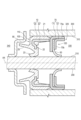
- FIG. 1 is a diagram showing a sealing device according to a first embodiment, illustrating a cross-sectional end surface along the axis of a rotating shaft.
- FIG. FIG. 2 is a partially enlarged view of FIG.
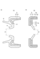
- FIG. 3(a) is a cross-sectional end view showing a first unit of the sealing device according to the first embodiment, showing the state before a rotating shaft is inserted therein
- FIG. 3(b) is a cross-sectional end view showing a second unit of the sealing device according to the first embodiment, showing the state before a rotating shaft is inserted therein.
- FIG. 4 is an exploded cut end view for explaining a manufacturing process of the second unit of the sealing device according to the first embodiment.
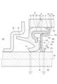
- 13 is a diagram showing a sealing device according to a second embodiment, showing a cross-sectional end surface along the axis of a rotating shaft.
- FIG. 1 is a schematic diagram for explaining a problem with a general sealing device.
- the sealing device 100 is disposed in the gap 320 so that the central axis AX of the sealing device 100 coincides with the axis of the rotating shaft 200 .
- a direction perpendicular to the central axis AX will be referred to as a radial direction.
- a direction going away from the central axis AX is referred to as the radially outer direction, and a direction going toward the central axis AX is referred to as the radially inner direction.
- the direction going around the central axis AX is referred to as the circumferential direction.
- the direction along the central axis AX may simply be referred to as the axial direction.
- one side (the right side in Figs. 1 and 2) in the direction along the central axis AX is the inner side (inside the machine) of the mechanism in which the sealing device 100 is provided, and this direction is referred to as the inner side 330.
- the other side (the left side in Figs. 1 and 2) in the direction along the central axis AX is the outer side (atmosphere side) of the mechanism in which the sealing device 100 is provided, and this direction is referred to as the outer side 340.
- the sealing device 100 of this embodiment is disposed in a gap 320 between an outer peripheral surface 210 of a rotating shaft 200 and an inner peripheral surface 310 of an axial hole 301 in a housing 300 having an axial hole 301 into which the rotating shaft 200 is inserted, and seals the gap 320.
- the sealing device 100 comprises a first lip portion 23, a second lip portion positioned on the inner side 330 of the first lip portion 23 within the housing 300, and a metal ring 70 that holds the second lip portion.
- the second lip portion is a conductive lip 50 made of a conductive material.
- the metal ring 70 has a contact portion 70 a that contacts the housing 300 , and an inward extending portion 70 b that extends radially inward from the contact portion 70 a and holds the conductive lip 50 .
- the sealing device 100 of this embodiment when the sealing device 100 is assembled to the housing 300 and the gap 320 of the axial hole 301 of the housing 300 is sealed, the metal ring 70 and the conductive lip 50 each form a part of a conductive path between the housing 300 and the rotating shaft 200. This ensures electrical continuity between the rotating shaft 200 and the housing 300 through the metal ring 70 and the conductive lip 50, that is, the rotating shaft can be earthed to the housing 300. This makes it possible to suppress the generation of electromagnetic noise from AM radio from the rotating shaft and the occurrence of electrolytic corrosion in the bearings. Since the sealing device 100 can be replaced with an existing sealing device, a space dedicated to an earth brush is not required, and the generation of brush wear powder can be prevented.
- this technology is ensured by the conductive lip 50 and the metal ring 70, which is a metal member, so that the electrical resistance of the conductive path from the rotating shaft 200 to the housing 300 can also be reduced.
- the conductive lip 50 by disposing the conductive lip 50 on the inner side 330 of the contact point between the first lip portion 23 and the rotating shaft 200 in the housing 300, that is, by disposing the conductive lip 50 on the inner side 330 of the point sealed by the first lip portion 23, it becomes possible to suppress the influence of foreign matter on the conductive lip 50. Therefore, it is possible to more reliably ensure electrical continuity by the conductive lip 50.
- the first lip portion 23 is a dust lip.
- the sealing device 100 combines the first lip portion 23, which is a dust lip, and the conductive lip 50, so that it is possible to achieve both dust sealing performance and conductivity while reducing the number of parts and installation space.
- the conductive lip 50 By arranging the conductive lip 50 on the inner side 330 of the contact point between the first lip portion 23, which is the dust lip, and the rotating shaft 200, conductivity can be imparted without impairing the dust seal performance.
- the sealing device 100 prevents foreign matter from entering from the outer side 340 to the inner side 330 by the first lip portion 23 and the conductive lip 50 . In particular, even in water-soaked environments where it was difficult to use earth brushes, electrical continuity can be ensured with a small number of parts.
- a separate oil seal (having an oil lip) may be arranged on the inner side 330 of the conductive lip 50.
- An example of a mechanism in which the sealing device 100 is disposed (attached) is a reduction gear for an electric vehicle (EV) or a fuel cell vehicle (FCV), and includes a housing 300 made of a metal material.
- the housing 300 has a shaft hole 301 into which the rotating shaft 200 is inserted.
- the sealing device 100 and the rotating shaft 200 the sealing device 100 is inserted and fixed into the shaft hole 301 first, and then the rotating shaft 200 is inserted.
- the sealing device 100 is configured with a first unit 110 having a first lip portion 23 and a second unit 120 having a conductive lip 50.
- the first unit 110 includes a seal body 10 .
- the seal body 10 is configured to include a core 30 made of a metallic material, and a seal body constituent member 20 made of an elastic body and integrated with the core 30.
- the seal body constituent member 20 includes a first lip portion 23.
- the seal body constituent member 20 is formed in an annular shape centered on the central axis AX.
- the seal body component 20 has, for example, a body abutment portion 21 formed in a cylindrical shape concentric with the central axis AX, and a body inward extension portion 22 extending radially inward in the form of an inner flange from one end (the end on the outer side 340) of the body abutment portion 21 in the axial direction.
- the first lip portion 23 extends obliquely from a radially inner end of the main body inward extending portion 22 radially inward and toward an outer side 340 (the left side in FIG. 2 ).
- the seal body component 20 has an outward extension portion 25 extending toward the outer side 340 from a surface of the outer side 340 of the body inward extension portion 22.
- the outward extension portion 25 is disposed radially outward from the first lip portion 23.
- a slinger 90 is fixed to the rotating shaft 200.
- the slinger 90 rotates in conjunction with the rotation of the rotating shaft 200.
- the slinger 90 is formed, for example, in a stepped flange shape that shifts in stages toward the inner side 330 in the radially outward direction.
- the outward extension portion 25 extends toward the inside of the gap between the slinger 90 and the outer circumferential surface 210 of the rotating shaft 200 .
- the seal body constituent member 20 is formed in a three-dimensional shape that corresponds to the movement trajectory of the cut end surface shape of the seal body constituent member 20 shown in Figure 2 when the cut end surface shape is rotated once around the central axis AX.
- a portion of the outer circumferential surface of the main body abutment portion 21 serves as a contact surface 21 a that is pressed circumferentially against the inner circumferential surface 310 of the shaft hole 301 .
- the first lip portion 23 is circumferentially pressed against an outer circumferential surface 210 of the rotating shaft 200, and slides against the outer circumferential surface 210 when the rotating shaft 200 rotates. Sealing performance is ensured by the pressure contact points between the contact surface 21 a and the inner circumferential surface 310 and the pressure contact points between the first lip portion 23 and the outer circumferential surface 210 .
- the material of the seal body component 20 can be a general sealing rubber material.
- elastic materials include synthetic rubbers such as nitrile rubber (NBR), hydrogenated nitrile rubber (H-NBR), acrylic rubber (ACM), and fluororubber (FKM).
- the seal body component 20 is formed as a single unit. More specifically, the seal body component 20 is integrally formed with the core metal 30 .
- the core bar 30 is placed in a molding die (not shown), uncrosslinked rubber material is injected, and then the cavity of the molding die is heated and pressurized to crosslink the rubber material, thereby obtaining a seal body 10 in which the seal body constituent member 20 and the core bar 30 are molded integrally.
- Examples of the metal material constituting the core bar 30 include stainless steel (SUS) and cold rolled steel (SPCC).
- the core bar 30 can be formed by pressing or forging.
- the core wire 30 has, for example, a tubular portion 31 formed in a cylindrical shape concentric with the central axis AX, and a core wire inward extension portion 32 extending radially inward in the form of an inner flange from one end (the end on the outer side 340) of the tubular portion 31 in the axial direction.
- the cylindrical portion 31 of the core metal 30 is embedded in the main body abutment portion 21. However, a portion of the cylindrical portion 31 may be exposed from the main body abutment portion 21 (from the seal main body constituent member 20).
- the core metal inward extending portion 32 is embedded in the main body inward extending portion 22.
- the core metal inward extending portion 32 may be formed in a flat flange shape, or may be partially bent to conform to the shape of the seal main body constituent member 20 as shown in FIG.
- the core bar 30 is formed into a three-dimensional shape that corresponds to the movement trajectory of the cut end surface shape of the core bar 30 shown in FIG. 2 when the cut end surface shape is rotated once around the central axis AX.
- the first unit 110 is constituted by the above-mentioned seal body 10 .
- the second unit 120 is composed of a metal ring 70 and a conductive lip 50 .
- the metal ring 70 is configured to include a first metal ring 71 and a second metal ring 72 .
- the first metal ring 71 has a first cylindrical portion 71a and a first inward extending portion 71b extending radially inward from the first cylindrical portion 71a.
- the second metal ring 72 has a second cylindrical portion 72a arranged along the inner surface of the first cylindrical portion 71a, and a second inward extension portion 72b extending radially inward from the second cylindrical portion 72a and arranged along the first inward extension portion 71b.
- the first cylindrical portion 71a and the second cylindrical portion 72a form the abutment portion 70a.
- the first inward extending portion 71b and the second inward extending portion 72b constitute an inward extending portion 70b.
- the conductive lip 50 is held by the inward extending portion 70b of the metal ring 70 by being sandwiched between the first inward extending portion 71b and the second inward extending portion 72b. In this way, the conductive lip 50 is held by being clamped between two metal rings (the first metal ring 71 and the second metal ring 72), thereby achieving a structure in which the conductive lip 50 is held more stably.
- the second inward extension portion 72b is positioned closer to the inner side 330 within the housing 300 than the first inward extension portion 71b.
- the inner peripheral end of the second inward extending portion 72b (the inner peripheral end 72c of the second metal ring 72) is located radially outward from the inner peripheral end of the first inward extending portion 71b (the inner peripheral end 71c of the first metal ring 71).
- the portion of the conductive lip 50 that extends radially inward from the inward extending portion 70b is bent toward the inner side 330 within the housing 300.
- the first cylindrical portion 71a is formed, for example, in a cylindrical shape concentric with the central axis AX.
- the first inward extending portion 71b extends radially inward from one end (the end on the outer side 340) of the first cylindrical portion 71a in the axial direction in the shape of an inner flange.
- the first cylindrical portion 71a is formed, for example, in a flat plate shape perpendicular to the central axis AX and in a doughnut shape.
- the first metal ring 71 is formed in a three-dimensional shape that corresponds to the movement trajectory of the cut end surface shape of the first metal ring 71 shown in FIG. 2 when the cut end surface shape is rotated once around the central axis AX.
- the outer peripheral surface of the first cylindrical portion 71 a is pressed circumferentially against the inner peripheral surface 310 of the shaft hole 301 .
- the second cylindrical portion 72a is formed, for example, in a cylindrical shape concentric with the central axis AX.
- the second inward extending portion 72b extends radially inward from one end (the end on the outer side 340) of the second cylindrical portion 72a in the axial direction in the shape of an inner flange.
- the second cylindrical portion 72a is formed, for example, in a flat plate shape perpendicular to the central axis AX and in a doughnut shape.
- the second metal ring 72 is formed in a three-dimensional shape that corresponds to the movement trajectory of the cut end surface shape of the second metal ring 72 shown in FIG. 2 when the cut end surface shape is rotated once around the central axis AX.
- the inner peripheral surface of the first cylindrical portion 71a is pressed circumferentially against the outer peripheral surface of the second cylindrical portion 72a.
- first metal ring 71 and the second metal ring 72 examples include stainless steel (SUS) or cold rolled steel (SPCC).
- SUS stainless steel
- SPCC cold rolled steel
- the first metal ring 71 and the second metal ring 72 can each be formed by pressing or forging.
- the conductive lip 50 is formed in a donut shape centered on the central axis AX.
- the conductive lip 50 is formed in a three-dimensional shape that corresponds to the movement trajectory of the cut end surface shape of the conductive lip 50 shown in FIG. 2 when the cut end surface shape is rotated once around the central axis AX.
- the tip portion (the radially inner end portion) of the conductive lip 50 contacts the outer peripheral surface 210 of the rotating shaft 200 in a circumferential manner, thereby ensuring electrical conductivity between the rotating shaft 200 and the conductive lip 50.
- the tip of the conductive lip 50 slides against the outer circumferential surface 210 when the rotating shaft 200 rotates.
- the conductive lip 50 is not required to have sealing properties.
- the material of the conductive lip 50 can be a material that is specialized for conductivity, such as conductive rubber or conductive resin.
- a preferred example of the material of the conductive lip 50 is conductive PTFE (fluororesin: PolyTetraFluoroEthylene).
- the outer peripheral edge of the conductive lip 50 is located radially inward from the inner peripheral surface of the first cylindrical portion 71a. Therefore, (unlike the conductive lip (front seal) in Patent Document 1), the outer peripheral edge of the conductive lip 50 does not reach the inner peripheral surface 310 (is spaced apart from the inner peripheral surface 310).
- the sealing device 100 is configured as described above.
- the first unit 110 and the second unit 120 of the sealing device 100 are each fixed to the housing 300 .
- the second unit 120 is fixed to the housing 300 by being inserted into the axial hole 301 so that the outer peripheral surface of the abutment portion 70 a, i.e., the outer peripheral surface of the first metal ring 71, is pressed against and fixed to the inner peripheral surface 310.
- the first unit 110 is fixed to the housing 300 by being inserted into the shaft hole 301 so that the contact surface 21 a is pressed against and fixed to the inner circumferential surface 310 . 2, the second unit 120 is disposed closer to the inner side 330 than the first unit 110.
- the first unit 110 and the second unit 120 are disposed adjacent to each other in the axial direction of the central axis AX. That is, for example, the second unit 120 and the first unit 110 are disposed such that the end face of the main body abutting portion 21 on the inner side 330 side contacts the surface of the inner circumferential end 71c on the outer side 340 side. Furthermore, the rotating shaft 200 is inserted into the inside of the first unit 110 and the inside of the second unit 120. As a result, the first lip portion 23 and the conductive lip 50 are each pressed against the outer circumferential surface 210 of the rotating shaft 200 in a circumferential manner. In this manner, an arrangement structure of the sealing device is obtained by incorporating the sealing device 100 into the housing 300 .
- the first lip portion 23 is inclined in a direction toward the outer side 340 of the housing 300 toward the tip side of the first lip portion 23.
- the conductive lip 50 is inclined in a direction toward the inner side 330 of the housing 300 toward the tip side of the conductive lip 50.
- the inclination direction of the first lip portion 23 and the inclination direction of the conductive lip 50 are opposite to each other.
- the operation of assembling the conductive lip 50 to the metal ring 70 to fabricate the second unit 120 can be performed, for example, as follows.
- the conductive lip 50 Before being assembled to the metal ring 70, the conductive lip 50 has, for example, a flat donut shape as shown in FIG.
- Such a conductive lip 50 is inserted into the first metal ring 71 so as to be disposed along the first inward extending portion 71b.
- the second metal ring 72 is press-fitted into the first metal ring 71 (the first metal ring 71 is fitted around the second metal ring 72), and the first metal ring 71 and the second metal ring 72 are crimped and fixed to each other, and a portion (the radially outer portion) of the conductive lip 50 is compressed and held by the first inward extending portion 71b and the second inward extending portion 72b.
- the inner peripheral end of the second inward extension portion 72b (the inner peripheral end 72c of the second metal ring 72) is located radially outward from the inner peripheral end of the first inward extension portion 71b (the inner peripheral end 71c of the first metal ring 71).
- the present invention is not limited to this example, and the conductive lip 50 may already be bent from a state before being sandwiched (compressed) by the first inward extension portion 71b and the second inward extension portion 72b.
- the portion of the conductive lip 50 that extends radially inward from the inward extension portion 70b may extend in a straight line, as shown in Figure 3 (b), or, even before the rotating shaft 200 is inserted into the sealing device 100, the portion of the conductive lip 50 that extends radially inward from the inward extension portion 70b may extend in an arc, as shown in Figure 2.
- the inner diameter D2 ( Figure 3(b)) of the conductive lip 50 is smaller than the inner diameter D1 ( Figure 3(a)) of the first lip portion 23.
- the contact area between the rotating shaft 200 and the conductive lip 50 is larger than the contact area between the rotating shaft 200 and the first lip portion 23 after the rotating shaft 200 is inserted into the sealing device 100. That is, it is possible to realize a structure in which the distance L2 is longer than the distance L1 shown in Fig. 2. This makes it possible to more reliably ensure electrical continuity by the conductive lip 50.
- the first lip portion 23 has higher rigidity than the conductive lip 50, and even if the contact area between the rotating shaft 200 and the first lip portion 23 is smaller than the contact area between the rotating shaft 200 and the conductive lip 50, the sealing performance of the first lip portion 23 can be sufficiently ensured.
- the sealing device 100 of this embodiment differs from the sealing device 100 of the first embodiment described above in the points described below, but in other respects is configured in the same manner as the sealing device 100 of the first embodiment described above.
- the sealing device 100 is configured to include the first unit 110 and the second unit 120 which are separate from each other.
- the sealing device 100 is constructed as a single unit.
- the dimension of the body abutment portion 21 of the seal body component 20 in the axial direction of the central axis AX is smaller than that of the first embodiment. Also, the protruding length of the body abutment portion 21 from the body inward extension portion 22 is smaller than that of the first embodiment.
- the sealing device 100 includes a metal ring 40 instead of the metal ring 70 .
- the metal ring 40 has an abutment portion 41 that abuts against the housing 300 , and an inward extension portion 42 that extends radially inward from the abutment portion 41 and holds the conductive lip 50 .
- the metal ring 40 is attached to the seal body 10 , and the conductive lip 50 is integrated with the seal body 10 by being sandwiched between the inward extension 42 and the seal body 10 . Therefore, compared to the first embodiment, the number of parts and the installation space can be reduced, and good integration between the conductive lip 50 and the seal body 10 can be achieved. More specifically, the metal ring 40 is fixed to the seal body component 20 .
- the contact portion 41 is formed, for example, in a cylindrical shape concentric with the central axis AX. However, the dimension of the contact portion 41 in the axial direction is extremely short.
- the contact portion 41 is fixed by crimping to the outer circumferential surface of the tip portion (the tip portion of the inner side 330) of the main body contact portion 21.
- the outer peripheral surface of the abutment portion 41 is pressed circumferentially against the inner peripheral surface 310 of the shaft hole 301 .
- the inward extending portion 42 of the metal ring 40 includes, for example, an outer flange portion 421 , an intermediate cylindrical portion 422 , and an inner flange portion 423 .
- the outer flange portion 421 extends radially inwardly from an end portion of the inner side 330 of the abutting portion 41 in the form of an inner flange.
- the outer flange portion 421 is disposed along the tip surface (end surface of the inner side 330) of the main body abutting portion 21.
- the outer flange portion 421 is formed in a flat plate shape perpendicular to the central axis AX and in a donut shape.
- the intermediate cylindrical portion 422 is formed in a cylindrical shape coaxial with the central axis AX.
- the intermediate cylindrical portion 422 extends from a radially inner end of the outer flange portion 421 toward the outer side 340.
- the intermediate cylindrical portion 422 is disposed along the inner circumferential surface of a portion of the main body abutting portion 21 that extends from the main body inward extending portion 22 toward the inner side 330.
- the inner flange portion 423 extends radially inward from the end portion of the intermediate cylindrical portion 422 on the outer side 340 side in an inner flange shape.
- the inner flange portion 423 is formed in a flat plate shape perpendicular to the central axis AX and in a donut shape.
- the inner flange portion 423 is disposed along a surface of the main body inward extending portion 22 facing the inner side 330.
- the metal ring 40 is formed into a three-dimensional shape that corresponds to the movement locus of the cut end surface shape of the metal ring 40 shown in FIG. 5 when the cut end surface shape is rotated once around the central axis AX.
- the inner flange portion 423 together with the main body inward extending portion 22 of the seal body constituent member 20 , clamps a portion (the radially outer portion) of the conductive lip 50 .
- the material of the metal ring 40 is similar to the material of the metal ring 70 (the first metal ring 71 and the second metal ring 72).
- the metal ring 40 can also be formed by pressing or forging.
- the seal body component 20 has a recess 22a in which a portion (the radially outer portion) of the conductive lip 50 is disposed. Therefore, during and after assembly of the sealing device 100, the conductive lip 50 can be more stably positioned and fixed to the seal body component 20, and ultimately to the seal body 10. In other words, the sealing device 100 is easy to manufacture and has excellent structural stability.
- the recess 22a is formed on the inner side 330 (the right side in FIG. 5) of the main body inward extension portion 22.
- the depth of the recess 22a (the dimension in the direction along the central axis AX) is less than the thickness dimension of the conductive lip 50 before assembly to the seal body 10, and the conductive lip 50 is clamped in a compressed state between the inner flange portion 423 and the bottom surface of the recess 22a.
- the outer periphery of the conductive lip 50 is positioned by the outer periphery of the recess 22a. Thus, the conductive lip 50 fits against the seal body component 20 .
- the distance from the inner peripheral edge to the outer peripheral edge of the conductive lip 50 in the radial direction i.e., ⁇ (outer diameter of the conductive lip 50) - (inner diameter of the conductive lip 50) ⁇ /2, is shorter than the distance from the outer peripheral surface 210 of the rotating shaft 200 to the inner peripheral surface 310 of the housing 300, i.e., ⁇ (inner diameter of the shaft hole 301) - (outer diameter of the rotating shaft 200) ⁇ /2.
- the outer peripheral edge of the conductive lip 50 is located radially inward from the contact surface 21a of the seal body component 20. More specifically, the outer peripheral edge of the conductive lip 50 is located radially inward from the inner peripheral surface of the intermediate cylindrical portion 422. This makes it easy to realize a structure in which the conductive lip 50 is fitted into the recess 22a.
- the conductive lip 50 and metal ring 40 can be assembled to the seal body 10, for example, by aligning the conductive lip 50 with the recess 22a and then fitting the metal ring 40 into the seal body 10.
- the inner end 40a (the inner end of the inner flange portion 423) of the inward extension portion 42 is located radially outward from the inner end of the portion of the seal body 10 that clamps the conductive lip 50 (the inner end 22d of the portion of the main body inward extension portion 22 that clamps the conductive lip 50).
- a portion of the conductive lip 50 (the radially outer portion) is clamped in a compressed state between the main body inward extension portion 22 and the inner flange portion 423, and by a mechanism similar to that described using Figures 4 and 3 (b) in the first embodiment, the portion of the conductive lip 50 that extends radially inward beyond the inward extension portion 42 is bent toward the inner side 330 within the housing 300.
- the sealing device 100 is fixed to the housing 300 by being inserted into the shaft hole 301 such that the outer circumferential surface and contact surface 21a of the abutment portion 41 are pressed against and fixed to the inner circumferential surface 310. Furthermore, the rotating shaft 200 is inserted into the sealing device 100. As a result, the first lip portion 23 and the conductive lip 50 are each pressed circumferentially against the outer circumferential surface 210 of the rotating shaft 200. As a result, an arrangement structure of the sealing device is obtained, which is configured by incorporating the sealing device 100 into the housing 300.
- the distance L2 is longer than the distance L1 shown in Figure 5, and the contact area between the rotating shaft 200 and the conductive lip 50 is larger than the contact area between the rotating shaft 200 and the first lip portion 23. Furthermore, before the rotating shaft 200 is inserted into the sealing device 100 (not shown), the inner diameter of the conductive lip 50 is smaller than the inner diameter of the first lip portion 23 .
- a sealing device that is disposed in a gap between an outer peripheral surface of a rotating shaft and an inner peripheral surface of a shaft hole in a housing having a shaft hole into which the rotating shaft is inserted, and seals the gap, A first lip portion; a second lip portion disposed inside the housing relative to the first lip portion; A metal ring that holds the second lip portion; Equipped with The second lip portion is a conductive lip made of a conductive material,
- the metal ring is a sealing device having an abutment portion that abuts against the housing, and an inward extension portion that extends radially inward from the abutment portion and holds the conductive lip.
- the first lip portion is inclined toward the outside of the housing toward the tip side of the first lip portion,
- the sealing device according to (1) wherein the conductive lip portion is inclined in a direction toward the inside of the housing toward the tip side of the conductive lip.
- the metal ring is configured to include a first metal ring and a second metal ring,
- the first metal ring is A first cylindrical portion; a first inward extending portion extending radially inward from the first cylindrical portion; having
- the second metal ring is A second cylindrical portion disposed along an inner circumferential surface of the first cylindrical portion; a second inward extending portion extending radially inward from the second cylindrical portion and disposed along the first inward extending portion,
- the first cylindrical portion and the second cylindrical portion constitute the abutment portion,
- the first inward extension portion and the second inward extension portion constitute the inward extension portion,
- the sealing device according to (1) or (2) wherein the conductive lip is held by being sandwiched between the first inward extension portion and the second inward extension
- the second inward extension portion is disposed on an inner side within the housing than the first inward extension portion, An inner circumferential end of the second inward extension portion is located radially outward from an inner circumferential end of the first inward extension portion,
- the sealing device according to claim 3 wherein a portion of the conductive lip that extends radially inward from the inward extension portion is bent toward the inside of the housing.
- the seal body includes: A core bar made of a metal material; a seal body component made of an elastic body and having the core metal integrated therewith;
- the present invention is configured with The sealing device according to any one of (1) to (4), wherein the seal body constituent member includes the first lip portion.
- the metal ring is attached to the seal body
- the sealing device according to (5) wherein the conductive lip is integrated with the seal body by being sandwiched between the inward extension portion and the seal body.
- An inner circumferential end of the inward extension portion is located radially outward from an inner circumferential end of a portion of the seal body that sandwiches the conductive lip,
- the sealing device according to claim 6, wherein a portion of the conductive lip that extends radially inward from the inward extension portion is bent toward the inside of the housing.
- Seal body 20 Seal body constituent member 21 Body abutment portion 21a Contact surface 22 Body inward extension portion 22a Recess 22d Inner peripheral end 23 First lip portion 25 Outer extension portion 30 Core metal 31 Cylindrical portion 31a Contact surface 32 Core metal inward extension portion 32a Contact surface 32b Bent portion 40 Metal ring 40a Inner peripheral end 41 Abutment portion 42 Inward extension portion 42a Recess 42b Bent portion 50 Conductive lip (second lip portion) 70 Metal ring 70a Contact portion 70b Inward extension portion 71 First metal ring 71a First cylindrical portion 71b First inward extension portion 71c Inner peripheral end 72 Second metal ring 72a Second cylindrical portion 72b Second inward extension portion 72c Inner peripheral end 90 Slinger 100 Sealing device 110 First unit 120 Second unit 200 Rotating shaft 210 Outer peripheral surface 300 Housing 301 Shaft hole 310 Inner peripheral surface 320 Gap 330 Inner side 340 Outer side 421 Outer flange portion 422 Intermediate cylindrical portion 423 Inner flange portion 1000 Sealing device 1201 First rotating shaft 1202 Second rotating shaft
Landscapes
- Engineering & Computer Science (AREA)
- General Engineering & Computer Science (AREA)
- Mechanical Engineering (AREA)
- Sealing With Elastic Sealing Lips (AREA)
Priority Applications (4)
| Application Number | Priority Date | Filing Date | Title |
|---|---|---|---|
| JP2025506652A JP7760092B2 (ja) | 2023-03-10 | 2024-02-22 | 密封装置 |
| KR1020257029447A KR20250143106A (ko) | 2023-03-10 | 2024-02-22 | 밀봉 장치 |
| CN202480015326.3A CN120787292A (zh) | 2023-03-10 | 2024-02-22 | 密封装置 |
| EP24770474.5A EP4678953A1 (en) | 2023-03-10 | 2024-02-22 | Sealing device |
Applications Claiming Priority (2)
| Application Number | Priority Date | Filing Date | Title |
|---|---|---|---|
| JP2023-037277 | 2023-03-10 | ||
| JP2023037277 | 2023-03-10 |
Publications (1)
| Publication Number | Publication Date |
|---|---|
| WO2024190361A1 true WO2024190361A1 (ja) | 2024-09-19 |
Family
ID=92754906
Family Applications (1)
| Application Number | Title | Priority Date | Filing Date |
|---|---|---|---|
| PCT/JP2024/006531 Ceased WO2024190361A1 (ja) | 2023-03-10 | 2024-02-22 | 密封装置 |
Country Status (5)
| Country | Link |
|---|---|
| EP (1) | EP4678953A1 (https=) |
| JP (1) | JP7760092B2 (https=) |
| KR (1) | KR20250143106A (https=) |
| CN (1) | CN120787292A (https=) |
| WO (1) | WO2024190361A1 (https=) |
Citations (6)
| Publication number | Priority date | Publication date | Assignee | Title |
|---|---|---|---|---|
| JP2014142065A (ja) | 2013-01-22 | 2014-08-07 | Carl Freudenberg Kg | シールリング及び該シールリングを備えるシール装置 |
| US20200103028A1 (en) * | 2018-10-01 | 2020-04-02 | Carl Freudenberg Kg | Sealing element |
| US20200103029A1 (en) * | 2018-10-01 | 2020-04-02 | Carl Freudenberg Kg | Sealing element |
| CN111043315A (zh) * | 2019-12-20 | 2020-04-21 | 嘉科(无锡)密封技术有限公司 | 一种接地式油封 |
| WO2022163675A1 (ja) * | 2021-01-27 | 2022-08-04 | Nok株式会社 | 密封装置 |
| JP2023037277A (ja) | 2021-09-03 | 2023-03-15 | 株式会社ダイフク | 物品搬送車 |
Family Cites Families (1)
| Publication number | Priority date | Publication date | Assignee | Title |
|---|---|---|---|---|
| KR101542570B1 (ko) | 2013-06-03 | 2015-08-06 | 다주건설 (주) | 수평 착정 장치 |
-
2024
- 2024-02-22 CN CN202480015326.3A patent/CN120787292A/zh active Pending
- 2024-02-22 EP EP24770474.5A patent/EP4678953A1/en active Pending
- 2024-02-22 WO PCT/JP2024/006531 patent/WO2024190361A1/ja not_active Ceased
- 2024-02-22 KR KR1020257029447A patent/KR20250143106A/ko active Pending
- 2024-02-22 JP JP2025506652A patent/JP7760092B2/ja active Active
Patent Citations (6)
| Publication number | Priority date | Publication date | Assignee | Title |
|---|---|---|---|---|
| JP2014142065A (ja) | 2013-01-22 | 2014-08-07 | Carl Freudenberg Kg | シールリング及び該シールリングを備えるシール装置 |
| US20200103028A1 (en) * | 2018-10-01 | 2020-04-02 | Carl Freudenberg Kg | Sealing element |
| US20200103029A1 (en) * | 2018-10-01 | 2020-04-02 | Carl Freudenberg Kg | Sealing element |
| CN111043315A (zh) * | 2019-12-20 | 2020-04-21 | 嘉科(无锡)密封技术有限公司 | 一种接地式油封 |
| WO2022163675A1 (ja) * | 2021-01-27 | 2022-08-04 | Nok株式会社 | 密封装置 |
| JP2023037277A (ja) | 2021-09-03 | 2023-03-15 | 株式会社ダイフク | 物品搬送車 |
Non-Patent Citations (1)
| Title |
|---|
| See also references of EP4678953A1 |
Also Published As
| Publication number | Publication date |
|---|---|
| EP4678953A1 (en) | 2026-01-14 |
| KR20250143106A (ko) | 2025-09-30 |
| JP7760092B2 (ja) | 2025-10-24 |
| CN120787292A (zh) | 2025-10-14 |
| JPWO2024190361A1 (https=) | 2024-09-19 |
Similar Documents
| Publication | Publication Date | Title |
|---|---|---|
| JP7214807B2 (ja) | 密封装置 | |
| JP7664978B2 (ja) | 導電構造、導電経路形成方法、及び、密封装置の通電方法 | |
| JP7475453B2 (ja) | 密封装置 | |
| JP2023138842A5 (ja) | 導電構造、導電経路形成方法、及び、密封装置の通電方法 | |
| JP7671417B2 (ja) | 導電構造体及び導電密封装置 | |
| JP6967155B2 (ja) | 密封装置 | |
| JP2024175009A (ja) | 導電性密封装置 | |
| JP7760092B2 (ja) | 密封装置 | |
| WO2024190338A1 (ja) | 密封装置 | |
| JP7693125B2 (ja) | 導電性摺動部材、密封装置、密封装置の製造方法 | |
| JP6674229B2 (ja) | 密封装置 | |
| JP7752273B1 (ja) | 導電構造体及び導電方法 | |
| JP7686894B1 (ja) | 導電構造体及び導電密封装置 | |
| JP7720738B2 (ja) | 密封装置 | |
| WO2026074896A1 (ja) | 導電性樹脂組成物、導電摺動体、及び導電構造体 | |
| CN121162689A (zh) | 导电密封结构 |
Legal Events
| Date | Code | Title | Description |
|---|---|---|---|
| 121 | Ep: the epo has been informed by wipo that ep was designated in this application |
Ref document number: 24770474 Country of ref document: EP Kind code of ref document: A1 |
|
| ENP | Entry into the national phase |
Ref document number: 2025506652 Country of ref document: JP Kind code of ref document: A |
|
| WWE | Wipo information: entry into national phase |
Ref document number: 2025506652 Country of ref document: JP Ref document number: 202480015326.3 Country of ref document: CN |
|
| ENP | Entry into the national phase |
Ref document number: 1020257029447 Country of ref document: KR Free format text: ST27 STATUS EVENT CODE: A-0-1-A10-A15-NAP-PA0105 (AS PROVIDED BY THE NATIONAL OFFICE) |
|
| WWE | Wipo information: entry into national phase |
Ref document number: 2024770474 Country of ref document: EP |
|
| NENP | Non-entry into the national phase |
Ref country code: DE |
|
| WWP | Wipo information: published in national office |
Ref document number: 202480015326.3 Country of ref document: CN |
|
| ENP | Entry into the national phase |
Ref document number: 2024770474 Country of ref document: EP Effective date: 20251010 |
|
| ENP | Entry into the national phase |
Ref document number: 2024770474 Country of ref document: EP Effective date: 20251010 |
|
| ENP | Entry into the national phase |
Ref document number: 2024770474 Country of ref document: EP Effective date: 20251010 |
|
| ENP | Entry into the national phase |
Ref document number: 2024770474 Country of ref document: EP Effective date: 20251010 |
|
| WWP | Wipo information: published in national office |
Ref document number: 2024770474 Country of ref document: EP |