WO2024190218A1 - アルミニウム合金バスバー - Google Patents
アルミニウム合金バスバー Download PDFInfo
- Publication number
- WO2024190218A1 WO2024190218A1 PCT/JP2024/004579 JP2024004579W WO2024190218A1 WO 2024190218 A1 WO2024190218 A1 WO 2024190218A1 JP 2024004579 W JP2024004579 W JP 2024004579W WO 2024190218 A1 WO2024190218 A1 WO 2024190218A1
- Authority
- WO
- WIPO (PCT)
- Prior art keywords
- aluminum alloy
- flat conductor
- bending
- bent portion
- aluminum
- Prior art date
- Legal status (The legal status is an assumption and is not a legal conclusion. Google has not performed a legal analysis and makes no representation as to the accuracy of the status listed.)
- Ceased
Links
Images



Classifications
-
- H—ELECTRICITY
- H01—ELECTRIC ELEMENTS
- H01R—ELECTRICALLY-CONDUCTIVE CONNECTIONS; STRUCTURAL ASSOCIATIONS OF A PLURALITY OF MUTUALLY-INSULATED ELECTRICAL CONNECTING ELEMENTS; COUPLING DEVICES; CURRENT COLLECTORS
- H01R25/00—Coupling parts adapted for simultaneous co-operation with two or more identical counterparts, e.g. for distributing energy to two or more circuits
- H01R25/16—Rails or bus-bars provided with a plurality of discrete connecting locations for counterparts
- H01R25/161—Details
-
- C—CHEMISTRY; METALLURGY
- C22—METALLURGY; FERROUS OR NON-FERROUS ALLOYS; TREATMENT OF ALLOYS OR NON-FERROUS METALS
- C22C—ALLOYS
- C22C21/00—Alloys based on aluminium
- C22C21/06—Alloys based on aluminium with magnesium as the next major constituent
- C22C21/08—Alloys based on aluminium with magnesium as the next major constituent with silicon
-
- C—CHEMISTRY; METALLURGY
- C22—METALLURGY; FERROUS OR NON-FERROUS ALLOYS; TREATMENT OF ALLOYS OR NON-FERROUS METALS
- C22C—ALLOYS
- C22C21/00—Alloys based on aluminium
-
- C—CHEMISTRY; METALLURGY
- C22—METALLURGY; FERROUS OR NON-FERROUS ALLOYS; TREATMENT OF ALLOYS OR NON-FERROUS METALS
- C22C—ALLOYS
- C22C21/00—Alloys based on aluminium
- C22C21/02—Alloys based on aluminium with silicon as the next major constituent
-
- C—CHEMISTRY; METALLURGY
- C22—METALLURGY; FERROUS OR NON-FERROUS ALLOYS; TREATMENT OF ALLOYS OR NON-FERROUS METALS
- C22C—ALLOYS
- C22C21/00—Alloys based on aluminium
- C22C21/06—Alloys based on aluminium with magnesium as the next major constituent
-
- C—CHEMISTRY; METALLURGY
- C22—METALLURGY; FERROUS OR NON-FERROUS ALLOYS; TREATMENT OF ALLOYS OR NON-FERROUS METALS
- C22F—CHANGING THE PHYSICAL STRUCTURE OF NON-FERROUS METALS AND NON-FERROUS ALLOYS
- C22F1/00—Changing the physical structure of non-ferrous metals or alloys by heat treatment or by hot or cold working
-
- C—CHEMISTRY; METALLURGY
- C22—METALLURGY; FERROUS OR NON-FERROUS ALLOYS; TREATMENT OF ALLOYS OR NON-FERROUS METALS
- C22F—CHANGING THE PHYSICAL STRUCTURE OF NON-FERROUS METALS AND NON-FERROUS ALLOYS
- C22F1/00—Changing the physical structure of non-ferrous metals or alloys by heat treatment or by hot or cold working
- C22F1/04—Changing the physical structure of non-ferrous metals or alloys by heat treatment or by hot or cold working of aluminium or alloys based thereon
-
- H—ELECTRICITY
- H01—ELECTRIC ELEMENTS
- H01M—PROCESSES OR MEANS, e.g. BATTERIES, FOR THE DIRECT CONVERSION OF CHEMICAL ENERGY INTO ELECTRICAL ENERGY
- H01M50/00—Constructional details or processes of manufacture of the non-active parts of electrochemical cells other than fuel cells, e.g. hybrid cells
- H01M50/50—Current conducting connections for cells or batteries
- H01M50/502—Interconnectors for connecting terminals of adjacent batteries; Interconnectors for connecting cells outside a battery casing
- H01M50/503—Interconnectors for connecting terminals of adjacent batteries; Interconnectors for connecting cells outside a battery casing characterised by the shape of the interconnectors
-
- H—ELECTRICITY
- H01—ELECTRIC ELEMENTS
- H01M—PROCESSES OR MEANS, e.g. BATTERIES, FOR THE DIRECT CONVERSION OF CHEMICAL ENERGY INTO ELECTRICAL ENERGY
- H01M50/00—Constructional details or processes of manufacture of the non-active parts of electrochemical cells other than fuel cells, e.g. hybrid cells
- H01M50/50—Current conducting connections for cells or batteries
- H01M50/502—Interconnectors for connecting terminals of adjacent batteries; Interconnectors for connecting cells outside a battery casing
- H01M50/521—Interconnectors for connecting terminals of adjacent batteries; Interconnectors for connecting cells outside a battery casing characterised by the material
- H01M50/522—Inorganic material
-
- H—ELECTRICITY
- H01—ELECTRIC ELEMENTS
- H01R—ELECTRICALLY-CONDUCTIVE CONNECTIONS; STRUCTURAL ASSOCIATIONS OF A PLURALITY OF MUTUALLY-INSULATED ELECTRICAL CONNECTING ELEMENTS; COUPLING DEVICES; CURRENT COLLECTORS
- H01R13/00—Details of coupling devices of the kinds covered by groups H01R12/70 or H01R24/00 - H01R33/00
- H01R13/02—Contact members
- H01R13/03—Contact members characterised by the material, e.g. plating, or coating materials
-
- H—ELECTRICITY
- H01—ELECTRIC ELEMENTS
- H01R—ELECTRICALLY-CONDUCTIVE CONNECTIONS; STRUCTURAL ASSOCIATIONS OF A PLURALITY OF MUTUALLY-INSULATED ELECTRICAL CONNECTING ELEMENTS; COUPLING DEVICES; CURRENT COLLECTORS
- H01R11/00—Individual connecting elements providing two or more spaced connecting locations for conductive members which are, or may be, thereby interconnected, e.g. end pieces for wires or cables supported by the wire or cable and having means for facilitating electrical connection to some other wire, terminal, or conductive member, blocks of binding posts
- H01R11/01—Individual connecting elements providing two or more spaced connecting locations for conductive members which are, or may be, thereby interconnected, e.g. end pieces for wires or cables supported by the wire or cable and having means for facilitating electrical connection to some other wire, terminal, or conductive member, blocks of binding posts characterised by the form or arrangement of the conductive interconnection between the connecting locations
-
- H—ELECTRICITY
- H01—ELECTRIC ELEMENTS
- H01R—ELECTRICALLY-CONDUCTIVE CONNECTIONS; STRUCTURAL ASSOCIATIONS OF A PLURALITY OF MUTUALLY-INSULATED ELECTRICAL CONNECTING ELEMENTS; COUPLING DEVICES; CURRENT COLLECTORS
- H01R2201/00—Connectors or connections adapted for particular applications
- H01R2201/26—Connectors or connections adapted for particular applications for vehicles
Definitions
- the present invention relates to an aluminum alloy busbar.
- Aluminum is a lightweight metal with good electrical conductivity, and is relatively inexpensive, so it is widely used for bus bars, electric wires, electrodes, and the like.
- Aluminum alloys used as conductive materials generally include industrially pure aluminum such as A1060 alloy and A1070 alloy, which are standardized by the Japanese Industrial Standards (JIS), as well as A6101 alloy.
- JIS Japanese Industrial Standards
- the electrical conductivity of A1060 alloy is guaranteed by JIS to be 61% IACS.
- A6101 alloy which has a guaranteed electrical conductivity of 55% IACS, is often used.
- A6101 alloy has been subjected to T6 treatment, and its standard mechanical properties are tensile strength of 220 MPa, yield stress of 195 MPa, and elongation of 15% (1.6 mm thickness, 50 mm gauge length).
- A6101 alloy has fine magnesium-silicon precipitates in the aluminum parent phase, and achieves high strength through the Orowan mechanism.
- A6101-T6 alloy has reduced workability in post-processing such as pressing and bending.
- Patent Document 1 discloses a method for manufacturing an aluminum alloy busbar. Specifically, the method is for manufacturing an aluminum alloy busbar in which a predetermined shape is obtained by edgewise bending an aluminum alloy rectangular wire. The method is characterized in that the processing part is heated to 100°C to 250°C during edgewise bending, and is held for 5 minutes or less before performing edgewise bending.
- the material of the aluminum alloy rectangular wire used is a T6 tempered aluminum alloy material containing 0.3 to 0.9% Mg, 0.2 to 1.2% Si, 0.2% or less Cu, 0.5% or less Fe, and the balance being aluminum and unavoidable impurities.
- the ratio A/B of the Vickers hardness A of the heated part to the Vickers hardness B of the non-heated part is 0.8 or more. This manufacturing method can improve the edgewise bending workability of the bent part while preventing a decrease in strength.
- Patent Document 1 the processed part is heated when edgewise bending is performed, which causes a problem that the material of the processed part changes and a difference in strength occurs between the heated part and the non-heated part.
- it since it is essential to heat the processed part, there is a problem that the manufacturing cost increases.
- the present invention was made in consideration of the problems inherent in the conventional technology.
- the object of the present invention is to provide an aluminum alloy busbar that has improved bending workability and electrical connection stability by controlling the structure of the material.
- An aluminum alloy bus bar comprises a flat conductor made of an aluminum alloy having a composition containing 0.35 to 0.8 mass % magnesium and 0.3 to 0.7 mass % silicon, with the remainder being aluminum and unavoidable impurities, and a plurality of Mg-Si-based acicular particles containing magnesium and silicon are dispersed inside the aluminum alloy, the average length of the Mg-Si-based acicular particles being 67.1 nm to 378.4 nm, and the number density of the Mg-Si-based acicular particles in the aluminum alloy being 4.5 x 10²⁰ / m3 to 6.8 x 10²¹ / m3 .
- the present invention by controlling the structure of the material, it is possible to provide an aluminum alloy busbar with improved bending workability and electrical connection stability.
- FIG. 1 is a perspective view that illustrates an example of an aluminum alloy bus bar according to the present embodiment.
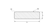
- FIG. 2 is a schematic cross-sectional view showing an example of a cross section of a flat conductor in an aluminum alloy bus bar.
- FIG. 3 is a schematic diagram for explaining the bending radius R of the edgewise bent portion of the flat conductor.
- FIG. 4 is a photograph showing the state of a flat conductor marked with a grid-like marker before bending.
- FIG. 5 is a photograph showing the state of a flat conductor marked with a grid-like marker after edgewise bending.
- FIG. 6 is a schematic diagram showing the cross-sectional shape of each of the square edge and the round edge of the flat conductor in this embodiment, and a photograph showing the appearance.
- FIG. 1 is a perspective view that illustrates an example of an aluminum alloy bus bar according to the present embodiment.
- FIG. 2 is a schematic cross-sectional view showing an example of a cross section of a flat conductor in an aluminum alloy
- FIG. 7 is a transmission electron microscope photograph showing the results of observing the test sample of Example 1 at a magnification of 200,000.
- FIG. 8 is a schematic diagram showing an example of the dispersion state of acicular particles inside an aluminum alloy.
- FIG. 9 shows an example of the results of observing a bent portion formed by edgewise bending at a magnification of 50 times, showing a case in which no cracks or necking were observed in the bent portion.
- FIG. 10 shows an example of the results of observing a bent portion formed by edgewise bending at a magnification of 50 times, in which cracks and necking were observed in the bent portion.
- FIG. 11 is a diagram for explaining observation points of the bent portion in FIG. 9 and FIG. FIG.
- FIG. 12 is a graph showing the relationship between the average length of precipitates and the yield stress in the test samples of Examples 1 to 12 and Comparative Examples 1 to 7.
- FIG. 13 is a graph showing the relationship between the number density of precipitates and the yield stress in the test samples of Examples 1 to 12 and Comparative Examples 1 to 7.
- the busbars are curved and twisted in various directions to form the routing path for the busbars.
- punching and pressing results in material loss, which is undesirable from the perspective of carbon neutrality and leads to increased processing costs.
- large dies are required, resulting in a significant increase in costs.
- the A6101-T6 alloy has low bending workability and a large bending radius, so busbars made from this alloy have long routing distances and are unsuitable for routing in small spaces.
- busbars are often made from rolled material, but because the shape is created through slitting, punching, and pressing, the corners are sharp, which raises concerns that they may act as points of stress concentration.
- busbars are required to have fastening reliability, vibration resistance, high temperature resistance, etc.
- the busbar needs to have sufficient strength to ensure electrical connectivity and vibration resistance.
- industrially pure aluminum is difficult to use for busbars because it does not have enough strength to ensure electrical connectivity and vibration resistance.
- A6101 alloy as an aluminum alloy for busbars is being considered, but this alloy has poor heat resistance, and there are concerns that its mechanical properties and other physical properties will change due to temperature changes in the in-vehicle environment.
- the aluminum alloy busbar of this embodiment has an optimized aluminum alloy composition and further controls the microstructure to form fine needle-shaped precipitates within the aluminum alloy structure, thereby improving bending workability and the stability of electrical connections.
- the aluminum alloy busbar 1 of this embodiment is made of an aluminum alloy and has a long flat conductor 10.
- the periphery of the central portion of the flat conductor 10 is covered with an insulating layer 20 having electrical insulation properties.
- the aluminum alloy busbar 1 has a plurality of bent portions 12.
- the bent portions 12 include an edgewise bent portion 12A that is bent in the width direction of the flat conductor 10, and a flatwise bent portion 12B that is bent in the thickness direction of the flat conductor 10.
- the flat conductor 10 in the aluminum alloy busbar 1 has through holes 11 at both ends, which can be fastened to other fastened members, for example, by using a fastening member.
- a fastening member for example, a bolt and nut are used as the fastening member and a terminal is used as the other fastened member
- the flat conductor 10 and the terminal can be fastened by inserting the threaded portion of the bolt into both the hole 11 of the flat conductor 10 and the hole of the terminal, and then screwing the nut into the threaded portion.
- the material and thickness of the insulator layer 20 are not particularly limited, so long as it can ensure electrical insulation against the flat conductor 10.
- resin materials that can be used to form the insulator layer 20 include vinyl chloride, heat-resistant vinyl chloride, cross-linked vinyl chloride, polyethylene, cross-linked polyethylene, foamed polyethylene, cross-linked foamed polyethylene, chlorinated polyethylene, polypropylene, polyamide (nylon), polyvinylidene fluoride, ethylene-tetrafluoroethylene copolymer, tetrafluoroethylene-hexafluoropropylene copolymer, tetrafluoroethylene, perfluoroalkoxyalkane, natural rubber, chloroprene rubber, butyl rubber, ethylene propylene rubber, chlorosulfonated polyethylene rubber, and silicone rubber. These materials may be used alone or in combination of two or more.
- the flat conductor 10 of the aluminum alloy busbar 1 is made of an aluminum alloy containing 0.35 to 0.8 mass% magnesium and 0.3 to 0.7 mass% silicon, with the remainder being aluminum and unavoidable impurities.
- the aluminum used as the base material in the aluminum alloy is preferably pure aluminum with a purity of 99.7% by mass or more.
- those with a purity of Al99.70 or more can be preferably used.
- examples include Al99.70, Al99.94, Al99.97, Al99.98, Al99.99, Al99.990, and Al99.995, each of which has a purity of 99.7% by mass or more.
- not only expensive high-purity aluminum ingots such as Al99.995 can be used as the aluminum ingots, but also affordable aluminum ingots with a purity of 99.7% by mass or more.
- Magnesium (Mg) is an element that can increase the strength of the flat conductor 10, which is an aluminum alloy plate, while minimizing the decrease in electrical conductivity. Magnesium is preferably contained in the aluminum alloy at 0.35 to 0.8 mass%. Silicon (Si) is an element that can improve the strength of the flat conductor 10 through solid solution strengthening and precipitation dispersion strengthening. Silicon is preferably contained in the aluminum alloy at 0.3 to 0.7 mass%.
- the aluminum alloy may contain iron, but the iron content is preferably 0.50 mass% or less.
- the aluminum alloy may contain trace amounts of unavoidable impurities.
- unavoidable impurities examples include nickel (Ni), rubidium (Rb), tin (Sn), vanadium (V), gallium (Ga), boron (B), sodium (Na), zirconium (Zr), manganese (Mn), lead (Pb), and calcium (Ca). These elements are unavoidably contained to the extent that they do not impair the effects of this embodiment and do not have a significant effect on the properties of the aluminum alloy of this embodiment. Elements that are already contained in the aluminum ingot used are also included as unavoidable impurities.
- the amount of unavoidable impurities in the aluminum alloy is preferably 0.07% by mass or less in total, and more preferably 0.05% by mass or less.
- the aluminum alloy constituting the flat conductor 10 has a plurality of dispersed Mg-Si-based needle-shaped particles containing magnesium and silicon.
- the aluminum alloy has a high dispersion of Mg-Si-based needle-shaped particles made of an intermetallic compound containing magnesium and silicon.
- Mg-Si-based needle-shaped particles are highly dispersed inside the aluminum alloy, and therefore the yield stress of the flat conductor 10 is increased, so that even when the hole 11 is fastened with a fastening member (e.g., a bolt and a nut), the stress relaxation around the hole 11 can be suppressed.
- the conductivity between the flat conductor 10 and the fastening member and between the flat conductor 10 and another fastened member can be increased.
- the high dispersion of Mg-Si-based needle-shaped particles can increase the yield stress of the flat conductor 10 while maintaining high bending workability. Therefore, even when the edgewise bent portion 12A and the flatwise bent portion 12B are formed in the aluminum alloy busbar 1, the occurrence of cracks and necking (constriction) in the bent portion 12 can be suppressed.
- the yield stress of the busbar is insufficient, when the busbar and other fastened members are fastened with bolts and nuts, the bolts and nuts will sink into the busbar due to stress relaxation, and the fastening force of the bolts and nuts will decrease. As a result, the bolts will loosen and the electrical resistance between the busbar and other fastened members will increase, making the electrical connection between the busbar and other fastened members unstable.
- the yield stress is increased. Therefore, the stress relaxation of the flat conductor 10 can be suppressed, and the electrical connection between the flat conductor 10 and other fastened members can be maintained in good condition.
- the bending workability of the flat conductor 10 can be improved and the occurrence of cracks and necking in the bent portion 12 of the flat conductor 10 can be suppressed.
- the aluminum alloy constituting the flat conductor 10 contains 0.35 to 0.8 mass % magnesium and 0.3 to 0.7 mass % silicon.
- the JIS standard 6000 series (Al-Mg-Si type) aluminum alloy is an age-precipitating type alloy, and the strength is achieved by forming a compound between magnesium and silicon.
- the strength of the 6000 series aluminum alloy can be increased by increasing the amount of magnesium and silicon added.
- the magnesium or silicon added in excess of the amount of Mg-Si precipitates can be dissolved in the aluminum parent phase to improve workability.
- the amount of magnesium and silicon added is increased at the same time, the amount of Mg-Si precipitates increases, leading to a decrease in bending workability. In order to suppress this, it is necessary to limit the amount of magnesium and silicon added.
- the composition range of the A6101 alloy is specified in JIS H4000 (aluminum and aluminum alloy plate and strip), with the magnesium additive amount being 0.35 to 0.80 mass %, and the silicon additive amount being 0.30 to 0.70 mass %.
- the aluminum alloy constituting the flat conductor 10 according to this embodiment was investigated within this composition range. As mentioned above, if the amount of magnesium and silicon added is reduced, the amount of Mg-Si precipitates produced is reduced, and the yield stress is reduced, and if it is increased too much, bending workability is reduced. For this reason, in order to obtain the effects of this embodiment, it is desirable to control the composition within the above range.
- the Mg-Si acicular particles dispersed inside the aluminum alloy constituting the flat conductor 10 preferably have an average length of 67.1 nm to 378.4 nm, more preferably 291.3 nm to 378.4 nm.
- the average length of the Mg-Si acicular particles within this range, stress relaxation of the flat conductor 10 can be suppressed, improving the stability of the electrical connection with other fastened members.
- the bending workability of the flat conductor 10 can be maintained at a high level, making it possible to perform edgewise bending, flatwise bending, and twist bending.
- the average length of the Mg-Si acicular particles can be determined by observing a sample of the aluminum alloy constituting the flat conductor 10 with a transmission electron microscope and measuring the lengths of multiple acicular particles.
- the length of the Mg-Si acicular particles refers to the longest distance between two different points on the contour of the acicular particles when the aluminum alloy is observed with a microscope.
- the aspect ratio and diameter of the Mg-Si acicular particles are not particularly limited, but the aspect ratio can be, for example, 4.4 to 68.2.
- the diameter of the Mg-Si acicular particles is the diameter perpendicular to the longitudinal direction of the acicular particles, and can be determined by observation with a transmission electron microscope.
- the number density of the Mg-Si acicular particles in the aluminum alloy constituting the flat conductor 10 is preferably 4.5 ⁇ 10 20 /m 3 to 6.8 ⁇ 10 21 /m 3 , and more preferably 4.5 ⁇ 10 20 /m 3 to 9.1 ⁇ 10 20 /m 3.
- the Mg-Si acicular particles are highly dispersed at 4.5 ⁇ 10 20 /m 3 or more, thereby increasing the yield stress, suppressing the stress relaxation of the flat conductor 10 and maintaining good electrical connection between the flat conductor 10 and other fastened members.
- the Mg-Si acicular particles are 6.8 ⁇ 10 21 /m 3 or less, the deterioration of the bending workability of the flat conductor 10 can be suppressed, so that edgewise bending, flatwise bending, and twist bending can be performed.
- the number density of Mg-Si acicular particles in an aluminum alloy can be calculated as follows: First, an aluminum alloy sample is observed under a transmission electron microscope to determine the number of acicular particles present in a given area, thereby calculating the areal density (number/m 2 ). The areal density is then multiplied by the thickness of the sample to calculate the number density (number/m 3 ) of the acicular particles.
- the flat conductor 10 has an allowable bending strain ⁇ , expressed by the following formula 1, exceeding 0.27.
- b is the width (mm) of the flat conductor 10
- Rmin is the minimum bending radius (mm) when the flat conductor 10 of the given width is bent edgewise.
- the width b of the flat conductor 10 is the width when observing a cross section perpendicular to the longitudinal direction of the flat conductor 10, as shown in Fig. 2.
- Rmin is the minimum value of the radius R from the bent position to the center of the bend when the flat conductor 10 of the given width is bent edgewise at room temperature, as shown in Fig. 3.
- Equation 1 takes into consideration the difference between theoretical bending strain and measured bending strain when the flat conductor 10 is bent edgewise.
- bending strain refers to the strain applied to the outermost surface of the outer curved surface portion (outer R portion) when the flat conductor 10 is bent edgewise.
- the theoretical bending strain ⁇ ' can be calculated from Equation 2 below.
- Equation 2 b is the plate width (mm) of the flat conductor 10
- R is the bending radius (mm) when the flat conductor 10 of the plate width is bent edgewise.
- the measured bending strain can be calculated from the amount of change in the lattice by edgewise bending the flat conductor 10 marked with a lattice-shaped marker, as shown in Figures 4 and 5.
- the allowable bending strain ⁇ of the flat conductor 10 exceeds 0.27, the bending workability of the flat conductor 10 is good. Therefore, even if the flat conductor 10 is bent edgewise, the occurrence of cracking and necking in the bent portion 12 can be suppressed. In contrast, for example, a flat conductor made of an A6101-T6 alloy has too high strength and poor bending workability, so the allowable bending strain ⁇ is 0.27 or less.
- the flat conductor 10 preferably has a yield stress of 55 to 201 MPa at room temperature.
- the yield stress of the flat conductor 10 is 55 MPa or more, stress relaxation of the flat conductor 10 can be suppressed, and therefore good electrical connection can be maintained between the flat conductor 10 and other fastened members.
- the yield stress of the flat conductor 10 is 201 MPa or less, the bending workability of the flat conductor 10 is good, and therefore cracking and necking of the bent portion 12 can be suppressed.
- the yield stress of the flat conductor 10 can be measured in accordance with JIS Z2241 (Method of tensile testing of metal materials).
- the busbars arranged inside the battery pack of a vehicle are used to connect the junction box (J/B), battery stack, etc., and possible methods for connecting these to the busbar include welding, solid-state welding, bolt fastening, etc.
- F the bolt axial force (N)
- T the tightening torque (N ⁇ m)
- d the nominal diameter of the threaded portion (m)
- K the torque coefficient.
- the pressure acting on the flange seat is the value obtained by dividing this bolt axial force F by the flange seat area S ( mm2 ). Note that the seat area is the area where the bolt flange actually contacts the busbar.
- F/S (MPa) is the lower limit of the yield stress required to prevent the busbar from collapsing.
- bolts such as M6 are often used.
- the fastening torque is 5 to 10 (N/m)
- the bearing surface pressure is about 42 to 83 (MPa).
- the fastening torque is not constant because the contact resistance changes depending on the material and surface properties of the busbar, but when safety factors are taken into account, it is preferable that the yield stress of the busbar is at least 100 MPa or more.
- the A6101 alloy is specified in various standards such as JIS, ASTM, and EN, it is necessary to ensure a yield stress of at least 55 MPa, as in the case of A6101-T64 specified in ASTM B317/B317M. Therefore, it is preferable that the yield stress of the flat conductor 10 according to this embodiment is 55 MPa or more.
- the yield stress of the flat conductor 10 is 120 MPa or more.
- the yield stress of the flat conductor 10 at room temperature is preferably 55 to 201 MPa, more preferably 100 to 201 MPa, and particularly preferably 120 to 201 MPa.
- the aluminum alloy busbar 1 of this embodiment is a conductive member that is connected to a junction box (J/B), a battery stack, etc., so it is preferable that its conductivity is as high as possible. Therefore, it is preferable that the conductivity of the flat conductor 10 is 55% IACS or more.
- the conductivity of the flat conductor 10 can be measured in accordance with JIS H0505 (Method of measuring volume resistivity and conductivity of non-ferrous metal materials).
- the flat conductor 10 preferably has an n-value of 0.07 or more, more preferably 0.15 or more, measured in accordance with JIS Z2241 (Metallic Material Tensile Test Method).
- the n-value is an index of the degree of work hardening of a metallic material, and the closer to 1 the value is, the greater the degree of work hardening.
- the hardness of the bent portion 12 after bending relative to the hardness of the bent portion 12 before bending [Hardness of the bent portion after bending]/[Hardness of the bent portion before bending] exceeds 1, so that it is possible to suppress the decrease in strength of the bent portion 12.
- the bent portion 12 when bending is performed on the flat conductor 10, when the n-value is 0.07 or more, the bent portion 12 is work-hardened, and therefore exhibits a high hardness value. Specifically, the hardness of the bent portion 12 after bending relative to the hardness of the bent portion 12 before bending exceeds 1.0 and is about 1.3. Therefore, by having the n value of the flat conductor 10 be 0.07 or more, it is possible to suppress a decrease in strength of the bent portion 12.
- the flat conductor 10 has at least the corners 13 at the bent portion 12 chamfered. It is also preferable that the flat conductor 10 has the entire corners 13 along the longitudinal direction chamfered.
- FIG. 6 shows a schematic cross-sectional shape of each of the square edge where the corners 13 are not chamfered and the round edge where the corners 13 are chamfered for the flat conductor 10 in this embodiment.
- FIG. 6 also shows an external photograph of each of the square edge and the round edge.
- the flat conductor 10 may have a square edge where the corners 13 are not chamfered and are approximately right angles.
- the corners 13 are chamfered from the viewpoint of preventing the corners 13 from acting as a starting point of stress concentration.
- the corners 13 are chamfered to be a round edge with a curved surface, the corners 13 are less likely to act as a starting point of stress concentration. Therefore, when the flat conductor 10 is bent, the occurrence of cracks can be further prevented.
- the aluminum alloy busbar 1 Next, a method for manufacturing the aluminum alloy busbar 1 according to this embodiment will be described.
- this manufacturing method first, aluminum, magnesium, and silicon are melted to have the above composition and cast to produce a cast billet. Then, the cast billet is subjected to a homogenization treatment.
- the homogenization treatment conditions can be 500 to 560°C for 4 to 10 hours.
- aluminum, magnesium, and silicon are melted to have the above composition and continuously cast to produce a cast rod, and then the cast rod is rolled to produce a wire rod.
- the homogenized cast billet or the wire obtained as described above is extruded using an extrusion molding machine to obtain an extruded material having a desired cross-sectional shape.
- the extrusion molding can be performed by hot extrusion, and the temperature during extrusion can be, for example, 350 to 500°C.
- the extrusion molding machine is not particularly limited, but a conform extruder can be used, for example.
- a die (metal mold) processed to obtain the desired cross-sectional shape can be used to obtain an extruded material with any cross-sectional shape.
- the part of the cavity of the die that corresponds to the above-mentioned corners can be curved to obtain an extruded material with chamfered corners.
- the extruded material extruded from the extruder is cooled with water, hot water, or cooling oil, or by air cooling.
- the cooled extruded material is wound up to any size.
- the cooled extruded material may be wound up in a coil shape around a bobbin, or it may be wound up in a hoop shape without using a bobbin.
- the wound extrusion material is subjected to aging heat treatment using a heating furnace.
- the heating furnace is not particularly limited, but an electric furnace can be used, for example.
- the conditions of the aging heat treatment are such that Mg-Si acicular particles with the above-mentioned average length and number density are formed inside the aluminum alloy.
- the conditions of the aging heat treatment can be, for example, a temperature of 225°C or higher for 2 hours or more, and preferably 225 to 300°C for 2 to 24 hours.
- the aged material that has been subjected to the aging heat treatment is bent into any shape at room temperature.
- the bending can be performed, for example, using a forming machine.
- an aluminum alloy busbar 1 which is made of a flat conductor 10 having at least one bent portion 12 selected from the group consisting of an edgewise bent portion 12A, a flatwise bent portion 12B, and a twisted bent portion formed by applying a twist.
- a manufacturing method equivalent to the T5 treatment can be used to obtain a flat conductor 10 having Mg-Si acicular particles with the above-mentioned average length and number density.
- a solution treatment may be performed before the aging heat treatment.
- the method for coating the periphery of the central portion of the flat conductor 10 with the electrically insulating insulator layer 20 is not particularly limited, and the insulator layer 20 can be formed by extrusion coating, for example.
- the insulator layer 20 can be formed on an aging-treated material by extrusion coating, and then the bent portion 12 can be formed by bending.
- the aluminum alloy busbar 1 includes a flat conductor 10 made of an aluminum alloy having a composition containing 0.35 to 0.8 mass % magnesium and 0.3 to 0.7 mass % silicon, with the remainder being aluminum and unavoidable impurities.
- a plurality of Mg-Si based acicular particles 16 containing magnesium and silicon are dispersed inside the aluminum alloy.
- the average length of the Mg-Si based acicular particles 16 is 67.1 nm to 378.4 nm, and the number density of the Mg-Si based acicular particles 16 in the aluminum alloy is 4.5 x 10²⁰ / m3 to 6.8 x 10²¹ / m3 .
- the flat conductor 10 of the aluminum alloy busbar 1 is made of an aluminum alloy containing a predetermined amount of magnesium and silicon, and furthermore, Mg-Si acicular particles 16 having a predetermined length are dispersed at a predetermined density inside the aluminum alloy. This configuration increases the yield stress of the flat conductor 10, so that even when fastened with a fastening member, stress relaxation around the hole 11 is suppressed, and high conductivity can be maintained between the flat conductor 10 and the fastening member and between the flat conductor 10 and other fastened members.
- the high dispersion of Mg-Si acicular particles increases the yield stress of the flat conductor 10 while also providing high bending workability, so that even when a bent portion 12 is formed in the flat conductor 10, the occurrence of cracks and necking in the bent portion 12 can be suppressed.
- the flat conductor 10 may have an allowable bending strain ⁇ , expressed by Equation 1, of more than 0.27.
- the allowable bending strain ⁇ of the flat conductor 10 exceeds 0.27, the bending workability of the flat conductor 10 is improved, so that even if edgewise bending is performed, the occurrence of cracking and necking in the bent portion 12 can be suppressed.
- the flat conductor 10 may have at least one bent portion 12. Since the flat conductor 10 has good bending workability, at least one bent portion 12 selected from the group consisting of an edgewise bent portion 12A, a flatwise bent portion 12B, and a twist bent portion can be easily formed in the flat conductor 10.
- the yield stress of the flat conductor 10 at room temperature measured in accordance with JIS Z2244 may be 55 to 201 MPa.
- the yield stress of the flat conductor 10 is 55 MPa or more, stress relaxation of the flat conductor 10 can be suppressed, so that good electrical connections can be maintained between the flat conductor 10 and the fastening member and between the flat conductor 10 and other fastened members.
- the yield stress of the flat conductor 10 is 201 MPa or less, deterioration of the bending workability of the flat conductor 10 can be suppressed, so that the bent portion 12 can be easily formed.
- At least the corners 13 of the bent portion 12 of the flat conductor 10 may be chamfered.
- the corners 13 are less likely to act as a starting point for stress concentration when the flat conductor 10 is bent, so that the occurrence of cracks can be further suppressed.
- the aluminum alloy busbar 1 according to the sixth aspect may be used as a wiring member in a vehicle.
- the wiring member is, for example, a member that is wired in a vehicle and electrically connects each device. Since the aluminum alloy busbar 1 has good bending workability and good electrical connection stability, it can be suitably used, for example, as a conductive member that is wired inside a battery pack mounted in a vehicle.
- Example 1 First, aluminum, silicon, and magnesium were weighed out in the proportions shown in Table 1. The weighed aluminum, silicon, and magnesium were then melted to prepare a molten metal, which was then poured into a die to obtain an ingot. The ingot was then subjected to a homogenization treatment to produce a cast billet. The homogenization treatment was carried out at 540°C for 4 hours, with a heating rate of 40°C/h.
- the obtained cast billet was hot extruded at 500°C and then water-cooled to obtain a long, flat extruded material.
- the obtained extruded material was then wound up, and the wound extruded material was subjected to aging heat treatment using a heating furnace.
- the aging heat treatment was performed at 225°C for 2 hours. In this way, a long test sample with a plate thickness t of 2.0 mm and a plate width b of 15.0 mm was obtained. Note that in this example, no solution treatment was performed prior to the aging heat treatment.
- Example 2 Test samples of each example were obtained in the same manner as in Example 1, except that the temperature and time of the aging heat treatment of the extruded material were changed as shown in Table 1.
- Example 7 Test samples of each example were obtained in the same manner as in Example 1, except that the ratio of each element was changed as shown in Table 1, and the temperature and time of the aging heat treatment of the extruded material were changed as shown in Table 1. However, in Example 7, the die was adjusted so that the test sample had a plate thickness t of 5.0 mm and a plate width b of 24.0 mm.
- Test samples for each example were obtained using the same process as in Example 1, except that the ratio of each element was changed as shown in Table 1, and the temperature and time of the aging heat treatment for the extruded material were changed as shown in Table 1.
- Comparative Example 2 First, aluminum, silicon, and magnesium were weighed in the proportions shown in Table 1, and an extruded material was obtained by the same process as in Example 1. Next, the obtained extruded material was wound, and the wound extruded material was subjected to solution treatment using a heating furnace. The solution treatment was performed at 540°C for 2 hours. Then, after the solution treatment, an aging heat treatment was performed using a heating furnace. The aging heat treatment was performed at 225°C for 8 hours. In this manner, the test sample of this example was obtained.
- the manufacturing method of Comparative Example 2 is a method equivalent to the T6 treatment.
- Comparative Example 3 Test samples of this example were obtained in the same manner as in Comparative Example 2, except that the aging heat treatment time was changed as shown in Table 1.
- the average length and number density of the precipitates were measured by observing the test samples of each example with a transmission electron microscope. Specifically, a test piece with a diameter of about 3 mm and a thickness of 100 ⁇ m or less was prepared from the test sample of each example, and then sliced using a twin-jet electrolytic polishing device. The sliced test piece was then observed with a transmission electron microscope.
- Figure 7 shows the results of observing a test piece made from the test sample of Example 1 at 200,000x magnification. As shown in Figure 7, in Example 1, it can be seen that multiple acicular particles 16 are dispersed inside the aluminum matrix 15. The length of the acicular particle 16A was then calculated from the longest distance between two different points on the contour of the acicular particle 16A, and the average length was calculated from the lengths of the multiple acicular particles 16A.
- the acicular particles 16A are arranged along the plane of the paper in FIG. 7, and therefore are observed as acicular precipitates in FIG. 7.
- the long axis of the acicular particles 16B crosses the plane of the paper in FIG. 7, and therefore they are observed as dots in FIG. 7, rather than needles. That is, for example, as shown in FIG. 8, when the acicular particles 16B are arranged approximately perpendicular to the acicular particles 16A, the acicular particles 16B are observed as dots in FIG. 7. Therefore, the number density of the precipitates was calculated by counting the number of acicular particles 16A and 16B present in the observation field to obtain the areal density, and then multiplying the areal density by the thickness of the test piece.
- Table 2 The average length and number density of the precipitates in the test samples of each example are summarized in Table 2.
- the minimum bending radius Rmin of the test sample of each example was measured.
- the minimum bending radius Rmin was determined by observing the bent portion with an optical microscope after edgewise bending at room temperature, and determining the smallest bending radius R when no macroscopic defects such as cracks or necking occurred. Therefore, even if the bent portion did not break, if defects such as cracks or necking occurred, the bending radius at that time was not determined as the minimum bending radius Rmin .
- Fig. 9 and Fig. 10 show an example of the results of observing a bent portion formed by edgewise bending with an optical microscope at a magnification of 50 times.
- Fig. 9 and Fig. 10 show the results of observing the outer curved surface portion (outer R portion) of the bent portion as shown in Fig. 11.
- Fig. 9 shows a case where no cracks or necking are observed on the outer curved surface portion of the bent portion.
- Fig. 10 shows a case where cracks and necking are observed on the outer curved surface portion of the bent portion.
- the minimum bending radius R min is defined as the minimum bending radius R min .
- the hardness of the bent portion of each test sample when it was bent at room temperature with the minimum bending radius shown in Table 2 was measured in accordance with JIS Z2244. Then, the hardness ratio was calculated from the hardness of the bent portion after bending to the hardness of the bent portion before bending ([hardness of the bent portion after bending]/[hardness of the bent portion before bending]). Furthermore, the allowable bending strain ⁇ was calculated according to Formula 1 from the plate width (mm) of the test sample and the minimum bending radius R min (mm) when the test sample of the plate width was bent edgewise at room temperature. The hardness ratio and allowable bending strain ⁇ of each test sample are summarized in Table 2.
- test samples of each example were bent edgewise to a bend radius of 30 mm, and the bent portion was observed to see whether defects occurred.
- the test samples of each example were bent edgewise at room temperature to a bend radius of 30 mm, and then the outer curved surface portion (outer R portion) of the bent portion was observed as shown in Figure 11.
- cases in which no macroscopic defects such as cracks or necking occurred on the outer curved surface portion of the bent portion were judged as " ⁇ ”.
- cases in which cracks or necking were observed on the outer curved surface portion of the bent portion were judged as " ⁇ ".
- Table 2 The judgment results for each test sample are summarized in Table 2.
- the average length of the Mg-Si-based precipitates was 67.1 nm to 378.4 nm, and the number density of the Mg-Si-based precipitates was 4.5 ⁇ 10 20 /m 3 to 6.8 ⁇ 10 21 /m 3.
- the average length of the Mg-Si-based precipitates was less than 67.1 nm, and the number density of the Mg-Si-based precipitates exceeded 6.8 ⁇ 10 21 /m 3.
- the yield stress of the test samples of Examples 1 to 12 was 100 to 201 MPa, but the yield stress of the test samples of Comparative Examples 1 to 7 exceeded 201 MPa except for Comparative Example 3.
- the test samples of Examples 1 to 12 had a minimum bending radius R min of 30 mm or less, while the test samples of Comparative Examples 1 to 7 had a minimum bending radius R min of 33 mm or more.
- FIG. 12 shows the relationship between the average length of precipitates and the yield stress in the test samples of Examples 1 to 12 and Comparative Examples 1 to 7.
- FIG. 13 shows the relationship between the number density of precipitates and the yield stress in the test samples of Examples 1 to 12 and Comparative Examples 1 to 7.
- FIG. 12 it can be seen that the yield stress tends to decrease as the average length of precipitates increases.
- FIG. 13 it can be seen that the yield stress tends to increase as the number density of precipitates increases. Therefore, it can be seen that an aluminum alloy with a desired yield stress can be obtained by adjusting the average length and number density of Mg-Si-based precipitates.
- the n values of the test samples of Examples 1 to 12 were 0.07 or more, while the n values of the test samples of Comparative Examples 1 to 7 were 0.06 or less. Furthermore, the hardness ratio ([hardness of bent portion after bending]/[hardness of bent portion before bending]) of the test samples of Examples 1 to 12 was 1.0 or more, and the ratio was 1.1 or more for all samples except Example 7. Therefore, it can be seen that when the average length and number density of Mg-Si-based precipitates are within the above ranges, the decrease in strength of the bent portion 12 can be suppressed.
- the allowable bending strain of the test samples of Examples 1 to 12 was greater than 0.27 and was 0.30 or more, while the allowable bending strain of the test samples of Comparative Examples 1 to 7 was 0.27 or less. Therefore, it can be seen that by having an allowable bending strain exceeding 0.27, the bending workability of the aluminum alloy is improved, and the occurrence of defects in the bent portion can be suppressed.
Landscapes
- Chemical & Material Sciences (AREA)
- Engineering & Computer Science (AREA)
- Materials Engineering (AREA)
- Mechanical Engineering (AREA)
- Metallurgy (AREA)
- Organic Chemistry (AREA)
- General Chemical & Material Sciences (AREA)
- Chemical Kinetics & Catalysis (AREA)
- Electrochemistry (AREA)
- Physics & Mathematics (AREA)
- Thermal Sciences (AREA)
- Crystallography & Structural Chemistry (AREA)
- Inorganic Chemistry (AREA)
- Conductive Materials (AREA)
Priority Applications (4)
| Application Number | Priority Date | Filing Date | Title |
|---|---|---|---|
| JP2025506595A JPWO2024190218A1 (https=) | 2023-03-13 | 2024-02-09 | |
| EP24770336.6A EP4682277A1 (en) | 2023-03-13 | 2024-02-09 | Aluminum alloy bus bar |
| CN202480012232.0A CN120677259A (zh) | 2023-03-13 | 2024-02-09 | 铝合金汇流条 |
| US19/297,460 US20250372931A1 (en) | 2023-03-13 | 2025-08-12 | Aluminum alloy bus bar |
Applications Claiming Priority (2)
| Application Number | Priority Date | Filing Date | Title |
|---|---|---|---|
| JP2023039057 | 2023-03-13 | ||
| JP2023-039057 | 2023-03-13 |
Related Child Applications (1)
| Application Number | Title | Priority Date | Filing Date |
|---|---|---|---|
| US19/297,460 Continuation US20250372931A1 (en) | 2023-03-13 | 2025-08-12 | Aluminum alloy bus bar |
Publications (1)
| Publication Number | Publication Date |
|---|---|
| WO2024190218A1 true WO2024190218A1 (ja) | 2024-09-19 |
Family
ID=92755352
Family Applications (1)
| Application Number | Title | Priority Date | Filing Date |
|---|---|---|---|
| PCT/JP2024/004579 Ceased WO2024190218A1 (ja) | 2023-03-13 | 2024-02-09 | アルミニウム合金バスバー |
Country Status (5)
| Country | Link |
|---|---|
| US (1) | US20250372931A1 (https=) |
| EP (1) | EP4682277A1 (https=) |
| JP (1) | JPWO2024190218A1 (https=) |
| CN (1) | CN120677259A (https=) |
| WO (1) | WO2024190218A1 (https=) |
Citations (6)
| Publication number | Priority date | Publication date | Assignee | Title |
|---|---|---|---|---|
| JPH0967659A (ja) * | 1995-08-31 | 1997-03-11 | Ykk Corp | Al−Mg−Si系アルミニウム合金の熱処理方法 |
| JP2016079475A (ja) * | 2014-10-20 | 2016-05-16 | 昭和電工株式会社 | 熱伝導性・導電性部材の製造方法 |
| JP2017110245A (ja) * | 2015-12-14 | 2017-06-22 | 株式会社神戸製鋼所 | 自動車用アルミニウム合金鍛造材 |
| JP2018206663A (ja) | 2017-06-07 | 2018-12-27 | 株式会社Uacj | アルミニウム合金バスバーの製造方法及びアルミニウム合金バスバー |
| JP2021533260A (ja) * | 2018-08-02 | 2021-12-02 | テスラ,インコーポレイテッド | ダイカスト用アルミニウム合金 |
| JP2023039057A (ja) | 2021-09-08 | 2023-03-20 | ギガフォトン株式会社 | 極端紫外光生成装置、及び電子デバイスの製造方法 |
-
2024
- 2024-02-09 CN CN202480012232.0A patent/CN120677259A/zh active Pending
- 2024-02-09 WO PCT/JP2024/004579 patent/WO2024190218A1/ja not_active Ceased
- 2024-02-09 JP JP2025506595A patent/JPWO2024190218A1/ja active Pending
- 2024-02-09 EP EP24770336.6A patent/EP4682277A1/en active Pending
-
2025
- 2025-08-12 US US19/297,460 patent/US20250372931A1/en active Pending
Patent Citations (6)
| Publication number | Priority date | Publication date | Assignee | Title |
|---|---|---|---|---|
| JPH0967659A (ja) * | 1995-08-31 | 1997-03-11 | Ykk Corp | Al−Mg−Si系アルミニウム合金の熱処理方法 |
| JP2016079475A (ja) * | 2014-10-20 | 2016-05-16 | 昭和電工株式会社 | 熱伝導性・導電性部材の製造方法 |
| JP2017110245A (ja) * | 2015-12-14 | 2017-06-22 | 株式会社神戸製鋼所 | 自動車用アルミニウム合金鍛造材 |
| JP2018206663A (ja) | 2017-06-07 | 2018-12-27 | 株式会社Uacj | アルミニウム合金バスバーの製造方法及びアルミニウム合金バスバー |
| JP2021533260A (ja) * | 2018-08-02 | 2021-12-02 | テスラ,インコーポレイテッド | ダイカスト用アルミニウム合金 |
| JP2023039057A (ja) | 2021-09-08 | 2023-03-20 | ギガフォトン株式会社 | 極端紫外光生成装置、及び電子デバイスの製造方法 |
Non-Patent Citations (1)
| Title |
|---|
| See also references of EP4682277A1 |
Also Published As
| Publication number | Publication date |
|---|---|
| CN120677259A (zh) | 2025-09-19 |
| JPWO2024190218A1 (https=) | 2024-09-19 |
| US20250372931A1 (en) | 2025-12-04 |
| EP4682277A1 (en) | 2026-01-21 |
Similar Documents
| Publication | Publication Date | Title |
|---|---|---|
| JP6698735B2 (ja) | 自動車用アルミ電線 | |
| CN103052729B (zh) | 铝合金导体及其制造方法 | |
| CN109923227B (zh) | 铝合金线、铝合金绞合线、包覆电线以及带端子电线 | |
| JP6678579B2 (ja) | アルミニウム合金線及びアルミニウム合金線の製造方法 | |
| US11810687B2 (en) | Aluminum alloy wire, aluminum alloy strand wire, covered electrical wire, and terminal-equipped electrical wire | |
| WO2016088888A1 (ja) | アルミニウム合金線材、アルミニウム合金撚線、被覆電線およびワイヤーハーネス、ならびにアルミニウム合金線材の製造方法 | |
| TWI413132B (zh) | 配線用電線導體、配線用電線、以及其等之製造方法 | |
| WO2016199564A1 (ja) | アルミニウム合金線、アルミニウム合金撚線、被覆電線およびワイヤーハーネス | |
| CN107978382A (zh) | 铝线以及使用该铝线的铝电线和线束 | |
| JP2023036892A (ja) | 被覆電線、端子付き電線、銅合金線、銅合金撚線、及び銅合金線の製造方法 | |
| JP2003105468A (ja) | 端子用アルミニウム合金材料および前記材料からなる端子 | |
| US10553327B2 (en) | Aluminum alloy conductor wire, aluminum alloy stranded wire, coated wire, wire harness and method of manufacturing aluminum alloy conductor wire | |
| CN112585700A (zh) | 包覆电线、带端子电线、铜合金线、铜合金绞合线以及铜合金线的制造方法 | |
| WO2024190218A1 (ja) | アルミニウム合金バスバー | |
| JP6288456B2 (ja) | 電線の製造方法、電線、及びワイヤーハーネス | |
| JP7145683B2 (ja) | フラットケーブル及びその製造方法 | |
| JP2016225159A (ja) | アルミニウム電線及びワイヤーハーネス | |
| WO2018084263A1 (ja) | 被覆電線、端子付き電線、銅合金線、及び銅合金撚線 | |
| US11017914B2 (en) | Covered electric wire, terminal-fitted electric wire, copper alloy wire, and copper alloy stranded wire | |
| RU2791313C1 (ru) | Электротехнический сплав на основе алюминия и изделие, выполненное из него | |
| US20200181741A1 (en) | Aluminum Alloy Wire, Aluminum Alloy Strand Wire, Covered Electrical Wire, and Terminal-Equipped Electrical Wire | |
| JP2018154927A (ja) | アルミニウム合金、アルミニウム合金を用いたアルミニウム合金電線、アルミニウム合金電線を用いた自動車用ワイヤーハーネス、及びアルミニウム合金素線の製造方法 |
Legal Events
| Date | Code | Title | Description |
|---|---|---|---|
| 121 | Ep: the epo has been informed by wipo that ep was designated in this application |
Ref document number: 24770336 Country of ref document: EP Kind code of ref document: A1 |
|
| WWE | Wipo information: entry into national phase |
Ref document number: 202517076457 Country of ref document: IN |
|
| WWE | Wipo information: entry into national phase |
Ref document number: 202480012232.0 Country of ref document: CN |
|
| ENP | Entry into the national phase |
Ref document number: 2025506595 Country of ref document: JP Kind code of ref document: A |
|
| WWE | Wipo information: entry into national phase |
Ref document number: 2025506595 Country of ref document: JP |
|
| WWP | Wipo information: published in national office |
Ref document number: 202517076457 Country of ref document: IN |
|
| WWP | Wipo information: published in national office |
Ref document number: 202480012232.0 Country of ref document: CN |
|
| WWE | Wipo information: entry into national phase |
Ref document number: 2024770336 Country of ref document: EP |
|
| NENP | Non-entry into the national phase |
Ref country code: DE |
|
| ENP | Entry into the national phase |
Ref document number: 2024770336 Country of ref document: EP Effective date: 20251013 |
|
| ENP | Entry into the national phase |
Ref document number: 2024770336 Country of ref document: EP Effective date: 20251013 |
|
| ENP | Entry into the national phase |
Ref document number: 2024770336 Country of ref document: EP Effective date: 20251013 |
|
| ENP | Entry into the national phase |
Ref document number: 2024770336 Country of ref document: EP Effective date: 20251013 |
|
| ENP | Entry into the national phase |
Ref document number: 2024770336 Country of ref document: EP Effective date: 20251013 |
|
| WWP | Wipo information: published in national office |
Ref document number: 2024770336 Country of ref document: EP |