WO2024190020A1 - 物体侵入検出システム、その検出方法及びプログラム - Google Patents
物体侵入検出システム、その検出方法及びプログラム Download PDFInfo
- Publication number
- WO2024190020A1 WO2024190020A1 PCT/JP2023/044544 JP2023044544W WO2024190020A1 WO 2024190020 A1 WO2024190020 A1 WO 2024190020A1 JP 2023044544 W JP2023044544 W JP 2023044544W WO 2024190020 A1 WO2024190020 A1 WO 2024190020A1
- Authority
- WO
- WIPO (PCT)
- Prior art keywords
- optical fiber
- vibration
- measurement point
- detection system
- detected
- Prior art date
- Legal status (The legal status is an assumption and is not a legal conclusion. Google has not performed a legal analysis and makes no representation as to the accuracy of the status listed.)
- Ceased
Links
Images





Classifications
-
- G—PHYSICS
- G01—MEASURING; TESTING
- G01H—MEASUREMENT OF MECHANICAL VIBRATIONS OR ULTRASONIC, SONIC OR INFRASONIC WAVES
- G01H9/00—Measuring mechanical vibrations or ultrasonic, sonic or infrasonic waves by using radiation-sensitive means, e.g. optical means
-
- G—PHYSICS
- G01—MEASURING; TESTING
- G01V—GEOPHYSICS; GRAVITATIONAL MEASUREMENTS; DETECTING MASSES OR OBJECTS; TAGS
- G01V8/00—Prospecting or detecting by optical means
- G01V8/10—Detecting, e.g. by using light barriers
- G01V8/20—Detecting, e.g. by using light barriers using multiple transmitters or receivers
- G01V8/24—Detecting, e.g. by using light barriers using multiple transmitters or receivers using optical fibres
-
- G—PHYSICS
- G08—SIGNALLING
- G08B—SIGNALLING SYSTEMS, e.g. PERSONAL CALLING SYSTEMS; ORDER TELEGRAPHS; ALARM SYSTEMS
- G08B13/00—Burglar, theft or intruder alarms
- G08B13/02—Mechanical actuation
Definitions
- This disclosure relates to an object intrusion detection system that detects the intrusion of an object, and a detection method and program thereof.
- the threshold voltage needs to be changed to detect objects, which may complicate the configuration.
- the objective of this disclosure is to provide an object intrusion detection system, a detection method, and a program that solve any of the problems described above.
- one aspect of the present disclosure is to A first optical fiber for detecting vibrations; a second optical fiber that is disposed at a different height from the first optical fiber and detects vibration; an intrusion object detection unit that determines whether or not the detection is a false positive depending on the number of optical fibers in which vibration is detected;
- the object intrusion detection system includes:
- one aspect of the present disclosure is to A first optical fiber for detecting vibrations; a second optical fiber that is disposed at a height position different from that of the first optical fiber and detects vibrations, determining whether or not the detection is erroneous depending on the number of optical fibers in which vibration is detected; Detection method.
- one aspect of the present disclosure is to A first optical fiber for detecting vibrations; a second optical fiber that is disposed at a height position different from that of the first optical fiber and detects vibrations, A process of determining whether or not the detection is erroneous depending on the number of optical fibers in which vibration is detected, It is a program that is executed by a computer.
- the present disclosure provides an object intrusion detection system, a detection method, and a program that solves any of the problems described above.
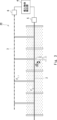
- FIG. 1 is a schematic diagram showing a schematic configuration of an object intrusion detection system according to an embodiment of the present invention
- 4 is a flowchart showing the flow of a detection method of the object intrusion detection system according to the present embodiment.
- 1 is a schematic diagram showing a schematic configuration of an object intrusion detection system according to an embodiment of the present invention
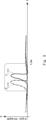
- FIG. 13 is a diagram showing a state in which a strong wind perpendicularly crosses a measurement point F 2,2 of the second optical fiber and a measurement point F 1,2 of the first optical fiber in that order. 13 is a diagram showing waveforms of vibration values at measurement points of the first and second optical fibers when a strong wind passes through.
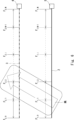
- FIG. 13 is a diagram showing a state in which a strong wind crosses a measurement point F 1,1 of a first optical fiber and a measurement point F 2,2 of a second optical fiber in this order in a diagonal direction. 13 is a diagram showing waveforms of vibration values at measurement points of the first and second optical fibers when a strong wind passes diagonally across the optical fibers;
- FIG. 1 is a schematic diagram showing a schematic configuration of an object intrusion detection system according to an embodiment of the present invention
- EMBODIMENT 1 1 is a schematic diagram showing a schematic configuration of an intrusion detection system according to the present embodiment.
- the intrusion detection system 1 according to the present embodiment includes a first optical fiber 2, a second optical fiber 3, and an intrusion object detection unit 4.
- the first optical fiber 2 is laid, for example, along a boundary line such as a perimeter fence or wall of a facility. This first optical fiber 2 is laid to detect intruders, such as people or animals, who cross the boundary line such as the perimeter fence. For this reason, the first optical fiber 2 is preferably positioned, for example, at a height position where vibrations caused by an intruder can be easily detected.
- the second optical fiber 3 is laid to suppress erroneous detection of an intruder by the first optical fiber 2.
- the second optical fiber 3 may be laid parallel to the first optical fiber 2 at a different height position from the first optical fiber 2.
- the second optical fiber 3 may be disposed at a predetermined height that is easily affected by strong winds and cannot be touched by people.
- the second optical fiber 3 is attached to a support or the like and laid at the predetermined height.
- the cause of the false detection is construction work, trains, airplanes, automobiles, etc., the second optical fiber 3 may be buried under the ground where it is easily affected by vibrations.
- the second optical fiber 3 is laid parallel to the first optical fiber 2, at a predetermined distance inward from the first optical fiber 2.
- both the first and second optical fibers 2, 3 vibrate in response to a strong wind that moves across the first and second optical fibers 2, 3.
- only the first optical fiber 2 vibrates in response to an intruder entering the boundary line.
- the intruding object detection unit 4 detects the intrusion of an intruder into the boundary line based on the characteristics of the first and second optical fibers 2 and 3. In other words, when vibrations are detected only in the first fiber, the intruding object detection unit 4 detects the intrusion of an intruder into the boundary line due to the vibrations.
- the intrusion object detection unit 4 determines that the detection is a false positive due to a strong wind or the like, and does not detect the intrusion of an intruder into the boundary line due to the vibrations. In this way, it is possible to clearly distinguish whether the vibrations of the first optical fiber 2 are due to a strong wind or the like, or due to an intruder, based on the vibrations of the second optical fiber 3. This makes it possible to suppress false detections of intruders.
- the intruding object detection unit 4 has the hardware configuration of a typical computer, including, for example, a processor such as a CPU (Central Processing Unit) and a GPU (Graphics Processing Unit), internal memory such as a RAM (Random Access Memory) and a ROM (Read Only Memory), storage devices such as a HDD (Hard Disk Drive) and an SSD (Solid State Drive), an input/output I/F for connecting peripheral devices such as a display, and a communication I/F for communicating with devices external to the device.
- a processor such as a CPU (Central Processing Unit) and a GPU (Graphics Processing Unit)
- internal memory such as a RAM (Random Access Memory) and a ROM (Read Only Memory)
- storage devices such as a HDD (Hard Disk Drive) and an SSD (Solid State Drive)
- an input/output I/F for connecting peripheral devices such as a display
- a communication I/F for communicating with devices external to the device.
- FIG. 2 is a flowchart showing the flow of the detection method of the object intrusion detection system according to the present embodiment.
- the intruding object detection unit 4 determines whether or not vibration has been detected in the first optical fiber 2 (step S101).
- step S101 determines whether or not vibration has been detected in the second optical fiber 3 (step S102). On the other hand, if the intruding object detection unit 4 determines that vibration has not been detected in the first optical fiber 2 (NO in step S101), it ends this process.
- the intruding object detection unit 4 determines that vibrations have been detected in the second optical fiber 3 (YES in step S102), it determines that this is a false detection due to strong winds or the like, and does not detect the intrusion of an intruder into the boundary line due to the vibrations (step S103). On the other hand, if the intruding object detection unit 4 determines that vibrations have not been detected in the second optical fiber 3 (NO in step S102), it detects the intrusion of an intruder into the boundary line due to the vibrations.
- the intruding object detection unit 4 detects the intrusion of an intruder into the boundary line due to the vibrations. Furthermore, when vibrations are detected in both the first optical fiber 2 and the second optical fiber 3, the intruding object detection unit 4 determines that this is a false detection due to a strong wind or the like, and does not detect the intrusion of an intruder into the boundary line due to the vibrations. This makes it possible to suppress false detection of an intruder due to a strong wind or the like.
- the number of optical fibers is two, the first and second optical fibers 2 and 3, but this is not limited to this, and the number of optical fibers may be three or more.
- the intruding object detection unit 4 may determine that a false detection has occurred if the number of optical fibers in which vibrations have been detected is greater than a predetermined number.
- the predetermined number is 1, in this modified example the predetermined number may be, for example, 2 or 3 or more, and may be determined arbitrarily by the user. The predetermined number may be determined according to the type of event or object that is to be detected as a false detection.
- EMBODIMENT 2 3 is a schematic diagram showing a schematic configuration of an object intrusion detection system according to the present embodiment.
- the object intrusion detection system 20 according to the present embodiment further includes a first optical fiber sensor 5 and a second optical fiber sensor 6.
- a first optical fiber sensor 5 is provided at the end of the first optical fiber 2.
- the first optical fiber sensor 5 measures the strain ⁇ L of the first optical fiber 2 through the phase difference ⁇ of the backscattered light in the gauge length section.
- the first optical fiber 2 operates as an independent vibration sensor in each gauge length section.
- the first optical fiber sensor 5 transmits a pulsed optical signal to the first optical fiber 2, and detects the vibration value of each measurement point on the first optical fiber 2 based on the reflected signal from each measurement point.
- a second optical fiber sensor 6 is provided at the end of the second optical fiber 3.
- the second optical fiber sensor 6 transmits a pulsed optical signal to the second optical fiber 3, and detects the vibration value of each measurement point on the second optical fiber 3 based on the reflected signal from each measurement point.
- the first optical fiber sensor 5 detects vibration values of each measurement point F1,0 , ..., F1,N of the first optical fiber 2 at regular intervals.
- the second optical fiber sensor 6 detects vibration values of each measurement point F2,0 , ..., F2 ,i , ..., F2 ,N of the second optical fiber 3 at regular intervals.
- the measurement points F 1,0 , . . . , F 1,i , . . . , F 1,N of the first optical fiber 2 correspond to the measurement points F 2,0 , . . . , F 2,N of the second optical fiber 3, respectively.
- Fig. 5 is a diagram showing waveforms of vibration values at the measurement points of the first and second optical fibers 2 and 3 when the strong wind passes.
- the waveform F1,2 (t) of the vibration value at the measurement point F1,2 of the first optical fiber 2 and the waveform F2,2 (t) of the vibration value at the measurement point F2,2 of the second optical fiber 3 are the same or similar.
- the waveform F2,2 (t) of the vibration value at the measurement point F2,2 of the second optical fiber 3 precedes the waveform F1,2 (t) of the vibration value at the measurement point F1,2 of the first optical fiber 2 in terms of time.
- Fig. 7 is a diagram showing waveforms of vibration values at the measurement points of the first and second optical fibers 2 and 3 when the strong wind crosses diagonally.
- the waveform F1,1 (t) of the vibration value at the measurement point F1,1 of the first optical fiber 2 and the waveform F2,2 (t) of the vibration value at the measurement point F2,2 of the second optical fiber 3 are the same or similar. Furthermore, after passing through the measurement point F1,1 of the first optical fiber 2, the strong wind passes through the measurement point F2,2 of the second optical fiber 3. For this reason, the waveform F1,1 (t) of the vibration value at the measurement point F1,1 of the first optical fiber 2 precedes in time the waveform F2,2 (t) of the vibration value at the measurement point F2,2 of the second optical fiber 3.
- the intruding object detection unit 4 checks whether the same or similar vibration waveform is occurring at the corresponding measurement point F2 ,i of the second optical fiber 3 and at measurement points F2 ,i ⁇ a within a predetermined distance from the measurement point F2, i during a predetermined period p.
- the value of a which indicates the degree to which diagonal wind is taken into account
- the value of p which indicates the extent to which past information is checked, may be set to optimal values determined experimentally.
- the intruding object detection unit 4 will not detect the intrusion of an intruder into the boundary line due to the vibration of measurement point F1 ,i , as a false detection due to strong winds.
- EMBODIMENT 3 8 is a schematic diagram showing a schematic configuration of an object intrusion detection system according to the present embodiment.
- an object intrusion detection system 30 according to the present embodiment 3 further includes a movement direction determination unit 7 that determines the movement direction of an object.
- the Doppler effect causes the vibration frequency at each measurement point on the first optical fiber 2 to increase and the vibration frequency at each measurement point on the second optical fiber 3 to decrease.
- the movement direction determination unit 7 compares the frequency of vibration at the measurement point of the first optical fiber 2 with the frequency of vibration at the measurement point of the second optical fiber 3. The movement direction determination unit 7 then determines that the object generating the vibration is moving in the direction of the optical fiber with the higher frequency of vibration at the measurement point of the first and second optical fibers 2, 3.
- the movement direction determination unit 7 determines that the vibration frequency at the measurement point of the first optical fiber 2 is higher than the vibration frequency at the measurement point of the second optical fiber 3, it determines that the vibrating object is moving in the direction of the first optical fiber 2. In this way, the movement direction of the object generating the sound can be easily determined by simply comparing the vibration frequencies at the measurement points of the first and second optical fibers 2, 3.
- the object intrusion detection system 30 may issue a warning, for example, to an object moving from the first optical fiber 2 to the second optical fiber 3, based on the object's movement direction determined by the movement direction determination unit 7.
- the present disclosure can also be realized, for example, by having a processor execute a computer program to perform the process shown in FIG. 2.
- the program includes instructions (or software code) that, when loaded into a computer, cause the computer to perform one or more functions described in the embodiments.
- the program may be stored on a non-transitory computer-readable medium or tangible storage medium.
- computer-readable medium or tangible storage medium may include random-access memory (RAM), read-only memory (ROM), flash memory, solid-state drive (SSD) or other memory technology, CD-ROM, digital versatile disc (DVD), Blu-ray® disk or other optical disk storage, magnetic cassette, magnetic tape, magnetic disk storage or other magnetic storage device.
- the program may be transmitted on a transitory computer-readable medium or communication medium.
- transitory computer-readable medium or communication medium may include electrical, optical, acoustic, or other forms of propagated signals.
- a part or all of the above-described embodiments can be described as, but is not limited to, the following supplementary notes.
- Appendix 1 A first optical fiber for detecting vibrations; a second optical fiber that is disposed at a different height from the first optical fiber and detects vibration; an intrusion object detection unit that determines whether or not the detection is a false positive depending on the number of optical fibers in which vibration is detected;
- An object intrusion detection system comprising: (Appendix 2) 2.
- the object intrusion detection system according to claim 1,
- the second optical fiber is laid in parallel to the first optical fiber at a different height position, a first optical fiber sensor that transmits an optical signal to the first optical fiber and detects a vibration value at each measurement point on the first optical fiber based on a reflected signal from the measurement point; a second optical fiber sensor that transmits an optical signal to the second optical fiber and detects a vibration value at each measurement point on the second optical fiber based on a reflected signal from the measurement point; Further comprising: Object intrusion detection system. (Appendix 4) 4.
- the intruding object detection unit is if a waveform of a vibration value at a measurement point of the first optical fiber is identical or similar to a waveform of at least one of a corresponding measurement point of the second optical fiber and a measurement point within a predetermined distance from the corresponding measurement point during a predetermined period, it is determined to be a false detection, and the intrusion of an object based on the vibration value is not detected.
- Object intrusion detection system (Appendix 5) 5.
- Object intrusion detection system is if a waveform of a vibration value at a measurement point of the first optical fiber is identical or similar to a waveform of at least one of a corresponding measurement point of the second optical fiber and a measurement point within a predetermined distance from the corresponding measurement point during a predetermined
- Reference Signs List 1 Object intrusion detection system 2 First optical fiber 3 Second optical fiber 4 Intrusion object detection unit 5 First optical fiber sensor 6 Second optical fiber sensor 7 Movement direction determination unit 20 Object intrusion detection system 30 Object intrusion detection system
Landscapes
- Physics & Mathematics (AREA)
- General Physics & Mathematics (AREA)
- Life Sciences & Earth Sciences (AREA)
- General Life Sciences & Earth Sciences (AREA)
- Geophysics (AREA)
- Burglar Alarm Systems (AREA)
Priority Applications (1)
| Application Number | Priority Date | Filing Date | Title |
|---|---|---|---|
| JP2025506486A JPWO2024190020A1 (https=) | 2023-03-16 | 2023-12-13 |
Applications Claiming Priority (2)
| Application Number | Priority Date | Filing Date | Title |
|---|---|---|---|
| JP2023042271 | 2023-03-16 | ||
| JP2023-042271 | 2023-03-16 |
Publications (1)
| Publication Number | Publication Date |
|---|---|
| WO2024190020A1 true WO2024190020A1 (ja) | 2024-09-19 |
Family
ID=92754687
Family Applications (1)
| Application Number | Title | Priority Date | Filing Date |
|---|---|---|---|
| PCT/JP2023/044544 Ceased WO2024190020A1 (ja) | 2023-03-16 | 2023-12-13 | 物体侵入検出システム、その検出方法及びプログラム |
Country Status (2)
| Country | Link |
|---|---|
| JP (1) | JPWO2024190020A1 (https=) |
| WO (1) | WO2024190020A1 (https=) |
Citations (3)
| Publication number | Priority date | Publication date | Assignee | Title |
|---|---|---|---|---|
| JP2000082187A (ja) * | 1998-07-02 | 2000-03-21 | Furukawa Electric Co Ltd:The | 侵入検知装置 |
| JP2006208061A (ja) * | 2005-01-26 | 2006-08-10 | Comsec:Kk | 侵入検知センサー |
| WO2021075145A1 (ja) * | 2019-10-18 | 2021-04-22 | 日本電気株式会社 | 光ファイバセンシングシステム及び事象特定方法 |
-
2023
- 2023-12-13 JP JP2025506486A patent/JPWO2024190020A1/ja active Pending
- 2023-12-13 WO PCT/JP2023/044544 patent/WO2024190020A1/ja not_active Ceased
Patent Citations (3)
| Publication number | Priority date | Publication date | Assignee | Title |
|---|---|---|---|---|
| JP2000082187A (ja) * | 1998-07-02 | 2000-03-21 | Furukawa Electric Co Ltd:The | 侵入検知装置 |
| JP2006208061A (ja) * | 2005-01-26 | 2006-08-10 | Comsec:Kk | 侵入検知センサー |
| WO2021075145A1 (ja) * | 2019-10-18 | 2021-04-22 | 日本電気株式会社 | 光ファイバセンシングシステム及び事象特定方法 |
Also Published As
| Publication number | Publication date |
|---|---|
| JPWO2024190020A1 (https=) | 2024-09-19 |
Similar Documents
| Publication | Publication Date | Title |
|---|---|---|
| JPWO2011001684A1 (ja) | 車両位置検出装置及び車両位置検出方法 | |
| US10697861B2 (en) | Structure abnormality detection device, structure abnormality detection method, storage medium, and structure abnormality detection system | |
| KR20190115180A (ko) | 주차보조시스템 및 이의 초음파센서 감지성능 향상 방법 | |
| US10641681B2 (en) | Structure abnormality detection system, structure abnormality detection method, and storage medium | |
| WO2012098836A1 (ja) | 車両方向特定装置、車両方向特定方法、及びそのプログラム | |
| KR101519255B1 (ko) | 차량 주변 소리 알림 시스템 및 그 방법 | |
| WO2012095939A1 (ja) | 車両台数特定装置及び車両台数特定方法 | |
| US10625670B2 (en) | Notification device and notification method | |
| JP2017194331A (ja) | 損傷検出システム、損傷検出装置、損傷検出方法及びプログラム | |
| JP2016203670A (ja) | 踏切障害物検知システム | |
| WO2024190020A1 (ja) | 物体侵入検出システム、その検出方法及びプログラム | |
| JP7021019B2 (ja) | 検出システム、検出装置、および検出方法 | |
| WO2018168218A1 (ja) | センサ接着状態判定システム、センサ接着状態判定装置及びセンサ接着状態判定方法 | |
| TWI541528B (zh) | 多元觸發之方法 | |
| JP7578290B2 (ja) | 光ファイバセンシングシステム、光ファイバセンシング機器、及び救助要請検知方法 | |
| KR102064000B1 (ko) | 잡음 감지 기능을 갖는 장애물 감지 장치와 잡음 감지 방법 | |
| CN107886661B (zh) | 一种基于振动能量累积的入侵事件判定方法 | |
| KR102569543B1 (ko) | 장애물 감지 시스템 및 장애물 감지 방법 | |
| JPWO2017104641A1 (ja) | 情報処理装置、情報処理方法、プログラム、及び、情報処理システム | |
| KR20180061091A (ko) | 센서를 이용한 건축물의 지진감지 알림 시스템 | |
| JP2015034793A (ja) | 障害物検知装置及び障害物検知方法 | |
| JP4974358B2 (ja) | 車長検出装置 | |
| JP6519115B2 (ja) | 車両用障害物検知装置 | |
| WO2021152787A1 (ja) | 構造物劣化検出システム、構造物劣化検出方法、及び構造物劣化検出装置 | |
| KR102036368B1 (ko) | 선로 검사 시스템 및 방법 |
Legal Events
| Date | Code | Title | Description |
|---|---|---|---|
| 121 | Ep: the epo has been informed by wipo that ep was designated in this application |
Ref document number: 23927624 Country of ref document: EP Kind code of ref document: A1 |
|
| WWE | Wipo information: entry into national phase |
Ref document number: 2025506486 Country of ref document: JP |
|
| NENP | Non-entry into the national phase |
Ref country code: DE |
|
| 122 | Ep: pct application non-entry in european phase |
Ref document number: 23927624 Country of ref document: EP Kind code of ref document: A1 |