WO2024189823A1 - 熱交換器およびそれを備えた空気調和装置 - Google Patents
熱交換器およびそれを備えた空気調和装置 Download PDFInfo
- Publication number
- WO2024189823A1 WO2024189823A1 PCT/JP2023/010084 JP2023010084W WO2024189823A1 WO 2024189823 A1 WO2024189823 A1 WO 2024189823A1 JP 2023010084 W JP2023010084 W JP 2023010084W WO 2024189823 A1 WO2024189823 A1 WO 2024189823A1
- Authority
- WO
- WIPO (PCT)
- Prior art keywords
- tube
- heat exchanger
- flat tubes
- flow path
- flat
- Prior art date
- Legal status (The legal status is an assumption and is not a legal conclusion. Google has not performed a legal analysis and makes no representation as to the accuracy of the status listed.)
- Ceased
Links
Images






Classifications
-
- F—MECHANICAL ENGINEERING; LIGHTING; HEATING; WEAPONS; BLASTING
- F28—HEAT EXCHANGE IN GENERAL
- F28D—HEAT-EXCHANGE APPARATUS, NOT PROVIDED FOR IN ANOTHER SUBCLASS, IN WHICH THE HEAT-EXCHANGE MEDIA DO NOT COME INTO DIRECT CONTACT
- F28D1/00—Heat-exchange apparatus having stationary conduit assemblies for one heat-exchange medium only, the media being in contact with different sides of the conduit wall, in which the other heat-exchange medium is a large body of fluid, e.g. domestic or motor car radiators
- F28D1/02—Heat-exchange apparatus having stationary conduit assemblies for one heat-exchange medium only, the media being in contact with different sides of the conduit wall, in which the other heat-exchange medium is a large body of fluid, e.g. domestic or motor car radiators with heat-exchange conduits immersed in the body of fluid
- F28D1/03—Heat-exchange apparatus having stationary conduit assemblies for one heat-exchange medium only, the media being in contact with different sides of the conduit wall, in which the other heat-exchange medium is a large body of fluid, e.g. domestic or motor car radiators with heat-exchange conduits immersed in the body of fluid with plate-like or laminated conduits
- F28D1/0308—Heat-exchange apparatus having stationary conduit assemblies for one heat-exchange medium only, the media being in contact with different sides of the conduit wall, in which the other heat-exchange medium is a large body of fluid, e.g. domestic or motor car radiators with heat-exchange conduits immersed in the body of fluid with plate-like or laminated conduits the conduits being formed by paired plates touching each other
- F28D1/0325—Heat-exchange apparatus having stationary conduit assemblies for one heat-exchange medium only, the media being in contact with different sides of the conduit wall, in which the other heat-exchange medium is a large body of fluid, e.g. domestic or motor car radiators with heat-exchange conduits immersed in the body of fluid with plate-like or laminated conduits the conduits being formed by paired plates touching each other the plates having lateral openings therein for circulation of the heat-exchange medium from one conduit to another
- F28D1/0333—Heat-exchange apparatus having stationary conduit assemblies for one heat-exchange medium only, the media being in contact with different sides of the conduit wall, in which the other heat-exchange medium is a large body of fluid, e.g. domestic or motor car radiators with heat-exchange conduits immersed in the body of fluid with plate-like or laminated conduits the conduits being formed by paired plates touching each other the plates having lateral openings therein for circulation of the heat-exchange medium from one conduit to another the plates having integrated connecting members
- F28D1/0341—Heat-exchange apparatus having stationary conduit assemblies for one heat-exchange medium only, the media being in contact with different sides of the conduit wall, in which the other heat-exchange medium is a large body of fluid, e.g. domestic or motor car radiators with heat-exchange conduits immersed in the body of fluid with plate-like or laminated conduits the conduits being formed by paired plates touching each other the plates having lateral openings therein for circulation of the heat-exchange medium from one conduit to another the plates having integrated connecting members with U-flow or serpentine-flow inside the conduits
-
- F—MECHANICAL ENGINEERING; LIGHTING; HEATING; WEAPONS; BLASTING
- F25—REFRIGERATION OR COOLING; COMBINED HEATING AND REFRIGERATION SYSTEMS; HEAT PUMP SYSTEMS; MANUFACTURE OR STORAGE OF ICE; LIQUEFACTION SOLIDIFICATION OF GASES
- F25B—REFRIGERATION MACHINES, PLANTS OR SYSTEMS; COMBINED HEATING AND REFRIGERATION SYSTEMS; HEAT PUMP SYSTEMS
- F25B39/00—Evaporators; Condensers
-
- F—MECHANICAL ENGINEERING; LIGHTING; HEATING; WEAPONS; BLASTING
- F28—HEAT EXCHANGE IN GENERAL
- F28D—HEAT-EXCHANGE APPARATUS, NOT PROVIDED FOR IN ANOTHER SUBCLASS, IN WHICH THE HEAT-EXCHANGE MEDIA DO NOT COME INTO DIRECT CONTACT
- F28D1/00—Heat-exchange apparatus having stationary conduit assemblies for one heat-exchange medium only, the media being in contact with different sides of the conduit wall, in which the other heat-exchange medium is a large body of fluid, e.g. domestic or motor car radiators
- F28D1/02—Heat-exchange apparatus having stationary conduit assemblies for one heat-exchange medium only, the media being in contact with different sides of the conduit wall, in which the other heat-exchange medium is a large body of fluid, e.g. domestic or motor car radiators with heat-exchange conduits immersed in the body of fluid
- F28D1/04—Heat-exchange apparatus having stationary conduit assemblies for one heat-exchange medium only, the media being in contact with different sides of the conduit wall, in which the other heat-exchange medium is a large body of fluid, e.g. domestic or motor car radiators with heat-exchange conduits immersed in the body of fluid with tubular conduits
- F28D1/053—Heat-exchange apparatus having stationary conduit assemblies for one heat-exchange medium only, the media being in contact with different sides of the conduit wall, in which the other heat-exchange medium is a large body of fluid, e.g. domestic or motor car radiators with heat-exchange conduits immersed in the body of fluid with tubular conduits the conduits being straight
- F28D1/0535—Heat-exchange apparatus having stationary conduit assemblies for one heat-exchange medium only, the media being in contact with different sides of the conduit wall, in which the other heat-exchange medium is a large body of fluid, e.g. domestic or motor car radiators with heat-exchange conduits immersed in the body of fluid with tubular conduits the conduits being straight the conduits having a non-circular cross-section
- F28D1/05366—Assemblies of conduits connected to common headers, e.g. core type radiators
- F28D1/05391—Assemblies of conduits connected to common headers, e.g. core type radiators with multiple rows of conduits or with multi-channel conduits combined with a particular flow pattern, e.g. multi-row multi-stage radiators
-
- F—MECHANICAL ENGINEERING; LIGHTING; HEATING; WEAPONS; BLASTING
- F28—HEAT EXCHANGE IN GENERAL
- F28F—DETAILS OF HEAT-EXCHANGE AND HEAT-TRANSFER APPARATUS, OF GENERAL APPLICATION
- F28F9/00—Casings; Header boxes; Auxiliary supports for elements; Auxiliary members within casings
- F28F9/02—Header boxes; End plates
- F28F9/0219—Arrangements for sealing end plates into casing or header box; Header box sub-elements
- F28F9/0221—Header boxes or end plates formed by stacked elements
-
- F—MECHANICAL ENGINEERING; LIGHTING; HEATING; WEAPONS; BLASTING
- F24—HEATING; RANGES; VENTILATING
- F24F—AIR-CONDITIONING; AIR-HUMIDIFICATION; VENTILATION; USE OF AIR CURRENTS FOR SCREENING
- F24F1/00—Room units for air-conditioning, e.g. separate or self-contained units or units receiving primary air from a central station
- F24F1/06—Separate outdoor units, e.g. outdoor unit to be linked to a separate room comprising a compressor and a heat exchanger
- F24F1/14—Heat exchangers specially adapted for separate outdoor units
-
- F—MECHANICAL ENGINEERING; LIGHTING; HEATING; WEAPONS; BLASTING
- F25—REFRIGERATION OR COOLING; COMBINED HEATING AND REFRIGERATION SYSTEMS; HEAT PUMP SYSTEMS; MANUFACTURE OR STORAGE OF ICE; LIQUEFACTION SOLIDIFICATION OF GASES
- F25B—REFRIGERATION MACHINES, PLANTS OR SYSTEMS; COMBINED HEATING AND REFRIGERATION SYSTEMS; HEAT PUMP SYSTEMS
- F25B13/00—Compression machines, plants or systems, with reversible cycle
-
- F—MECHANICAL ENGINEERING; LIGHTING; HEATING; WEAPONS; BLASTING
- F28—HEAT EXCHANGE IN GENERAL
- F28F—DETAILS OF HEAT-EXCHANGE AND HEAT-TRANSFER APPARATUS, OF GENERAL APPLICATION
- F28F17/00—Removing ice or water from heat-exchange apparatus
- F28F17/005—Means for draining condensates from heat exchangers, e.g. from evaporators
-
- F—MECHANICAL ENGINEERING; LIGHTING; HEATING; WEAPONS; BLASTING
- F28—HEAT EXCHANGE IN GENERAL
- F28F—DETAILS OF HEAT-EXCHANGE AND HEAT-TRANSFER APPARATUS, OF GENERAL APPLICATION
- F28F2230/00—Sealing means
Definitions
- This disclosure relates to a headerless heat exchanger and an air conditioning device equipped with the same.
- a heat exchanger is a type of heat exchanger that is made by stacking a plurality of heat exchange members and exchanges heat between a first fluid such as a refrigerant and a second fluid such as air.
- One such heat exchanger is a headerless heat exchanger (see, for example, Patent Document 1).
- the heat exchanger of Patent Document 1 has a plurality of heat transfer paths for the first fluid that are provided in the stacking direction of the heat exchange members that are substantially rectangular in shape, each of which extends in the longitudinal direction of the heat exchange members, and a header path that extends in the stacking direction of the heat exchange members and connects the plurality of heat transfer paths.
- the heat exchange members are plates, and the unevenness provided on the plates forms a heat transfer path for the refrigerant between the plate and the adjacent plate on one side of the stacking direction, and also forms an air path between the plate and the adjacent plate on the other side of the stacking direction.
- the heat transfer paths for the refrigerant are connected to each other by providing a through hole in the portion where the plate and the adjacent plate on the other side of the stacking direction are joined.
- the heat exchanger of Patent Document 1 is constructed by stacking plates, with the refrigerant heat transfer flow path and the air flow path formed by the unevenness on the plates, and the refrigerant header flow path formed by through holes in the joints of the plates. Therefore, the plate pitch and the total width of the refrigerant heat transfer flow path and the air flow path in the plate stacking direction are determined by the size of the unevenness on the plates (i.e. the depth of the grooves or the height of the protrusions).
- the width of the air flow path in the plate stacking direction can be changed by the size of the unevenness, there is a limit to how much the unevenness can be changed because the unevenness is processed directly on the plates, and also, if an attempt is made to widen the width of the air flow path, the width of the refrigerant heat transfer flow path will become narrower.
- the heat exchanger of Patent Document 1 has a low degree of freedom in designing the air flow path.
- This disclosure has been made to solve the problems described above, and aims to increase the freedom in designing the air flow path in a headerless heat exchanger.
- the first heat exchanger is a heat exchanger including a plurality of flat tubes arranged in a first direction and each extending in a second direction intersecting the first direction, the flat tubes having a tube wall with a heat transfer flow path through which a fluid flows in the internal space, the tube walls having flat tube side wall portions facing each other in the first direction, the tube side wall portions having through holes formed therein, the adjacent flat tubes having connecting portions that connect the tube walls and communicate the heat transfer flow paths inside the tube walls, the connecting portions being constituted by connecting protrusions that protrude in the first direction from the periphery of the through hole formed in at least one of the opposing tube side wall portions of the adjacent flat tubes.
- the air conditioner according to the present disclosure also includes a refrigerant circuit in which a compressor, the above-mentioned heat exchanger, an expansion valve, and an indoor heat exchanger are connected via refrigerant piping, and a fluid circulates.
- a heat transfer flow path for a fluid is provided within the tube wall of the flat tube, and adjacent flat tubes have connecting parts that connect the tube walls and communicate the heat transfer flow paths, and the connecting parts protrude in a first direction from the peripheral part of the through hole in the tube side wall part. Therefore, by changing the length of the connecting parts, the width in the first direction of the air flow path outside the connecting parts can be changed, so that the width in the first direction of the air flow path can be increased without narrowing the width in the first direction of the heat transfer flow path of the fluid. This allows for greater freedom in designing the air flow paths in a headerless heat exchanger.
- FIG. 1 is a perspective view showing a schematic configuration of a heat exchanger according to a first embodiment
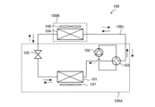
- FIG. 2 is a refrigerant circuit diagram of an air conditioner equipped with the heat exchanger of FIG. 1.
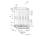
- FIG. 2 is a perspective view showing a configuration of a flat tube of the heat exchanger of FIG. 1 .
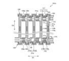
- FIG. 2 is a longitudinal sectional view of the heat exchanger of FIG. 1 .
- 5 is a partial cross-sectional view showing the AA cross section of the part surrounded by an ellipse in FIG. 4.
- FIG. 11 is a perspective view showing a schematic configuration of a heat exchanger according to a second embodiment.
- FIG. 7 is a longitudinal sectional view of the heat exchanger of FIG. 6 .
- FIG. 8 is a diagram showing an example of the configuration of a connecting portion enclosed in a square in FIG. 7 .
- FIG. 11 is a perspective view showing a configuration of a heat exchanger according to a third embodiment.
- FIG. 11 is a perspective view showing a schematic configuration of a heat exchanger according to a fourth embodiment.
- FIG. 11 is a longitudinal sectional view of the heat exchanger of FIG. 10 .
- FIG. 11 is a cross-sectional view of the heat exchanger of FIG. 10 taken along plane B, as viewed from above.
- 11 is a cross-sectional view of the heat exchanger of FIG. 10 taken along plane C, as viewed from above.
- FIG. FIG. 13 is a perspective view showing a schematic configuration of a heat exchanger according to a fifth embodiment.
- a vertical cross-sectional view showing the configuration of a positional regulation portion for a flat tube of a heat exchanger according to embodiment 6.
- FIG. 1 is a perspective view showing a schematic configuration of a heat exchanger according to the first embodiment.
- the heat exchanger 101 has a plurality of flat tubes 10 arranged in a first direction D1 and connected to each other.
- the flat tubes 10 extend in a direction in which the tube axis Ax extends (hereinafter, also referred to as the tube axis direction), and have a flat shape that is long in one direction in a cross section perpendicular to the tube axis Ax.
- the first direction D1 in which the plurality of flat tubes 10 are arranged is referred to as a stacking direction
- the tube axis direction of the flat tubes 10 is referred to as a second direction D2 or the longitudinal direction of the flat tubes 10
- the longitudinal direction of the cross section of the flat tubes 10 is referred to as a third direction D3 or the short direction of the flat tubes 10.
- the heat exchanger 101 is defined as being installed so that the stacking direction (first direction D1) of the flat tubes 10 is the left-right direction.
- Each flat tube 10 is defined as being arranged so that its tube axis Ax is in the up-down direction perpendicular to the stacking direction (first direction D1) and its short side direction (third direction D3) is in the front-to-back direction perpendicular to the tube axis direction and the stacking direction.
- the arrangement of the heat exchanger 101, or the angle between the stacking direction (first direction D1) of the flat tubes 10 in the heat exchanger 101 and the tube axis direction (second direction D2) of each flat tube 10, is not limited to the above case.
- the heat exchanger 101 may be arranged at an angle so that the tube axis direction of each flat tube 10 is inclined with respect to the vertical direction.
- the heat exchanger 101 when the heat exchanger 101 is installed so that the stacking direction (first direction D1) of the flat tubes 10 is the left-right direction, the heat exchanger 101 may be configured so that the tube axis direction of each flat tube 10 is inclined with respect to the vertical direction.
- Gaps that are air flow paths P2 are formed between the tube walls 11 of adjacent flat tubes 10 in the stacking direction (first direction D1), and air flows through each gap in the heat exchanger 101 along the short side direction of the flat tubes 10 (third direction D3).
- the flat tube 10 arranged at one end of the stacking direction among the plurality of flat tubes 10 is provided with a first pipe a and a second pipe b which serve as an inlet and outlet for a fluid (e.g., a refrigerant, etc.) in the heat exchanger 101.
- a fluid e.g., a refrigerant, etc.
- the fluid flowing through the flat tube 10 may be a refrigerant, or may be water, brine, etc.
- a fluid flow path is provided between the first pipe a and the second pipe b.
- the fluid flow path is provided in the plurality of flat tubes 10.
- the heat exchanger 101 exchanges heat between air and a fluid.
- the fluid flowing through the plurality of flat tubes 10 is defined as a refrigerant.
- Adjacent flat tubes 10 have connecting portions 19 for connecting the tube walls 11 of the adjacent flat tubes.
- Each flat tube 10 has a tube wall 11 and connecting protrusions 19a, 19b (see FIG. 3 described below) that extend outward from the tube wall 11 in a first direction D1 and constitute the connecting portion 19.
- the flat tubes 10 have a tube structure that maintains an internal space through which the refrigerant flows along their longitudinal direction (second direction D2), i.e., from the upper end to the lower end of the tube wall 11. The detailed structure of the flat tubes 10 will be described later.
- the heat exchanger 101 is provided with tube sealing portions 20 that close each open end 1e on both sides in the longitudinal direction (second direction D2) of the flat tubes 10.
- the tube sealing portions 20 are provided for each flat tube 10 at two locations, the upper and lower sides of the flat tube.
- the tube sealing portions 20 are joined to the open end 1e of the flat tube 10 by a joining means such as brazing or adhesive.
- FIG. 2 is a refrigerant circuit diagram of an air-conditioning device 100 equipped with the heat exchanger 101 of FIG. 1. As shown in FIG. 2, the heat exchanger 101 constitutes part of a refrigerant circuit 100c through which the refrigerant circulates in the air-conditioning device 100.
- the air conditioning device 100 has a compressor 102, a heat exchanger 101, an expansion valve 105, an indoor heat exchanger 104, and a four-way valve 103.
- the compressor 102, the heat exchanger 101, the expansion valve 105, and the four-way valve 103 are provided in the outdoor unit 100A
- the indoor heat exchanger 104 is provided in the indoor unit 100B.
- the first pipe a and the second pipe b (see FIG. 1), which serve as the inlet and outlet of the refrigerant of the heat exchanger 101, are connected to the four-way valve 103 and the expansion valve 105 of the refrigerant circuit 100c.
- the compressor 102, heat exchanger 101, expansion valve 105, indoor heat exchanger 104, and four-way valve 103 are connected to each other via refrigerant piping to form a refrigerant circuit 100c in which the refrigerant can circulate.
- the operation of the compressor 102 performs a refrigeration cycle in which the refrigerant circulates through the compressor 102, heat exchanger 101, expansion valve 105, and indoor heat exchanger 104 while undergoing a phase change.
- the outdoor unit 100A is provided with an outdoor fan 107 that forces outdoor air to pass through the heat exchanger 101.
- the heat exchanger 101 exchanges heat between the refrigerant and the outdoor airflow generated by the operation of the outdoor fan 107.
- the indoor unit 100B is provided with an indoor fan 106 that forces indoor air to pass through the indoor heat exchanger 104.
- the indoor heat exchanger 104 exchanges heat between the refrigerant and the indoor airflow generated by the operation of the indoor fan 106.
- the operation of the air conditioning device 100 can be switched between cooling operation and heating operation.
- the direction of refrigerant flow during cooling operation is indicated by a dashed arrow
- the direction of refrigerant flow during heating operation is indicated by a solid arrow.
- the four-way valve 103 is a solenoid valve that switches the refrigerant flow path in response to switching between cooling operation and heating operation of the air conditioning device 100.
- the four-way valve 103 guides the refrigerant from the compressor 102 to the heat exchanger 101 and guides the refrigerant from the indoor heat exchanger 104 to the compressor 102, and during heating operation, guides the refrigerant from the compressor 102 to the indoor heat exchanger 104 and guides the refrigerant from the heat exchanger 101 to the compressor 102.
- the refrigerant compressed by the compressor 102 is sent to the heat exchanger 101.
- the refrigerant releases heat to the outdoor air and is condensed.
- the refrigerant is then sent to the expansion valve 105, where it is reduced in pressure and then sent to the indoor heat exchanger 104.
- the refrigerant then absorbs heat from the indoor air in the indoor heat exchanger 104 and evaporates, before returning to the compressor 102. Therefore, when the air conditioning device 100 is in cooling operation, the heat exchanger 101 functions as a condenser, and the indoor heat exchanger 104 functions as an evaporator.
- the refrigerant compressed by the compressor 102 is sent to the indoor heat exchanger 104.
- the refrigerant releases heat to the indoor air and is condensed.
- the refrigerant is then sent to the expansion valve 105, where it is reduced in pressure and then sent to the heat exchanger 101.
- the refrigerant then absorbs heat from the outdoor air in the heat exchanger 101 and evaporates, before returning to the compressor 102. Therefore, when the air conditioning device 100 is in heating operation, the heat exchanger 101 functions as an evaporator, and the indoor heat exchanger 104 functions as a condenser.
- FIG. 3 is a perspective view showing the configuration of the flat tubes 10 of the heat exchanger 101 of FIG. 1.
- FIG. 4 is a longitudinal cross-sectional view of the heat exchanger 101 of FIG. 1.
- FIG. 5 is a partial cross-sectional view showing the A-A cross section of the part surrounded by an ellipse in FIG. 4.
- the refrigerant flow path of the heat exchanger 101 and the structure of the flat tubes 10 are described in detail with reference to FIG. 1 to FIG. 5.
- the direction of refrigerant flow when the heat exchanger 101 is used as a condenser is indicated by solid white arrows.
- dashed white arrows the direction of air flow is indicated by dashed white arrows.
- the tube wall 11 has substantially flat tube side wall portions 10a and 10b facing each other in the first direction D1, and curved connecting wall portions 10c and 10d connecting the tube side wall portions 10a and 10b at the respective ends of the tube side wall portions 10a and 10b on both sides in the third direction D3.
- the tube side wall portions 10a and 10b each have a rectangular shape with a long side extending in the longitudinal direction (second direction D2) of the flat tube 10 and a short side extending in the lateral direction (third direction D3) of the flat tube 10.
- the tube side wall portions 10a and 10b are each flat, the "flat shape" in this application does not have to be a surface composed of a completely flat surface, and may have a structure that appears to be flat as a whole.
- a depression, a protrusion, or a wave shape may be formed in part of the flat area.
- the wall portion on the left side of the pipe wall 11 is the pipe side wall portion 10a
- the wall portion on the right side of the pipe wall 11 is the pipe side wall portion 10b.
- the left pipe side wall portion 10a has a through hole h1a that penetrates in the first direction D1
- the right pipe side wall portion 10b has a through hole h1b that penetrates in the first direction D1.
- the connecting portion 19 of the adjacent flat tubes 10 has a cylindrical shape with a hollow portion Sg penetrating in the first direction D1.
- the connecting portion 19 is composed of a connecting protrusion 19a or 19b extending from the peripheral portion of the through hole h1a or h1b in at least one of the tube side wall portions 10a and 10b facing each other in the adjacent flat tubes 10 to the side of the facing tube side wall portion 10b or 10a.
- the connecting portion 19 is composed of cylindrical connecting protrusions 19a and 19b formed in both tube side wall portions 10a and 10b facing each other in the adjacent flat tubes 10.
- Such through holes h1a, h1b and connecting protrusions 19a, 19b can be formed, for example, by a burring process in which a hole is made in the flat portion of the flat tube 10 and the flat portion of the periphery is deformed so as to rise into a cylindrical shape.
- the connecting portion 19 connects the through holes h1a and h1b provided in the tube side wall portions 10a and 10b with the hollow portion Sg, thereby communicating the internal spaces of adjacent tube walls 11.
- the connecting portion 19 also has the function of dividing the inner hollow portion Sg from the air flow path P2, which is the space outside the connecting portion 19.
- the through holes h1a, h1b, and the connecting portion 19 are formed inward from the opening ends 1e on both sides in the longitudinal direction (second direction D2) of the flat tubes 10.
- the through holes h1a, h1b, the connecting protrusions 19a, and the connecting protrusions 19b of each flat tube 10 are formed below the upper opening end 1e of the flat tube 10 and above the lower opening end 1e of the flat tube 10.
- Such flat tubes 10 can be manufactured, for example, by forming through holes h1a and h1b and connecting protrusions 19a and 19b in advance in the base material of the flat tube 10, and then shaping the base material by roll forming. Also, the connecting protrusions 19a and 19b may be formed by raising the periphery of the holes when forming the through holes h1a and h1b in the base material of the flat tube 10.
- a metal material with high thermal conductivity such as aluminum, copper, or brass is used.
- the refrigerant flow path in the heat exchanger 101 is provided in the tube wall 11 of each flat tube 10 and has a heat transfer flow path P1a extending in the longitudinal direction of the flat tube 10 (second direction D2), and a header flow path P1b extending in the stacking direction of the flat tubes 10 (first direction D1) and connecting the heat transfer flow paths P1a of the flat tubes 10.
- One end of the header flow path P1b extending in the first direction D1 is connected to the first pipe a (see FIG. 1).
- the above-mentioned through holes h1a, h1b, and hollow portion Sg of the connecting portion 19 constitute the header flow path P1b, and the refrigerant flows through the hollow portion Sg.
- the connecting portion 19 is formed of a part of the flat tube 10, and the portion of the header flow path P1b that is arranged between the tube walls 11 of the flat tube 10 is the hollow portion Sg inside the connecting portion 19. Therefore, in the heat exchanger 101, the header flow path P1b is formed in the flat tube 10, which is the heat exchange member, so there is no need to provide a header pipe in addition to the multiple flat tubes 10, resulting in a headerless configuration.
- a first partition 30 is provided inside each flat tube 10, extending in the longitudinal direction of the flat tube 10 (second direction D2, up-down direction) and dividing the internal space of the tube wall 11 of the flat tube 10 in the lateral direction of the flat tube 10 (third direction D3, front-to-rear direction).
- the upper end 30e of the first partition 30 is provided below the upper opening end 10e of the flat tube 10.
- a turn-back flow path P1at is formed in the upper part of the internal space of the tube wall 11, through which the refrigerant can flow in the front-to-rear direction (third direction D3). That is, in the example of FIG. 5, the heat transfer flow path P1a of the refrigerant has an inverted U-shape including the turn-back flow path P1at.
- the refrigerant flow path of the heat exchanger 101 is composed of a plurality of heat transfer flow paths P1a and a header flow path P1b and a header flow path P1c (see FIG. 3) that are arranged in parallel in the front and rear directions at the bottom of the heat exchanger 101.
- the header flow path P1b is composed of hollow portions Sg of a plurality of connecting portions 19 arranged at the front side at the bottom of the heat exchanger 101.
- the header flow path P1c is composed of hollow portions (not shown) of a plurality of connecting portions 18 arranged at the rear side at the bottom of the heat exchanger 101.
- the right end of the front header flow path P1b is connected to the first pipe a
- the right end of the rear header flow path P1c is connected to the second pipe b.
- the heat exchanger 101 shown in Figures 1 and 3 to 5 is one example of the heat exchanger 101 of the present disclosure, and the shape of the heat transfer flow path P1a, the presence or absence, number and arrangement of the first partitions 30 in the flat tubes 10, and the arrangement of the first pipe a and the second pipe b in the heat exchanger 101 can be changed as appropriate.
- a high-temperature, high-pressure gaseous refrigerant flows into the heat exchanger 101 from the first pipe a.
- the high-temperature, high-pressure gaseous refrigerant first flows into the header flow path P1b that penetrates the lower front side of the multiple flat tubes 10 in the left-right direction, and flows through the header flow path P1b from right to left.
- the high-temperature, high-pressure gaseous refrigerant is distributed and flows into the heat transfer flow paths P1a provided in each of the tube walls 11 of the multiple flat tubes 10.
- the high-temperature, high-pressure gaseous refrigerant that flows into each heat transfer flow path P1a flows upward along the front side of the internal space of the tube wall 11, flows backward along the return flow path P1at (see Figure 5) at the upper part of the internal space of the tube wall 11, and then flows downward along the rear side of the internal space of the tube wall 11.
- the high-temperature, high-pressure gaseous refrigerant exchanges heat with the air flowing through the gaps between the tube walls 11 of the flat tubes 10 (i.e., the air flow path P2) through the tube walls 11, and condenses to become a high-pressure gas-liquid two-phase refrigerant.
- the high-pressure gas-liquid two-phase refrigerant from the multiple heat transfer paths P1a flows into the header path P1c (see FIG. 3) that penetrates the lower rear side of the multiple flat tubes 10, and merges in the header path P1c. As shown in FIG. 1 and FIG.
- the high-pressure gas-liquid two-phase refrigerant that merges in the header path P1c flows out of the heat exchanger 101 (for example, the expansion valve 105 of the refrigerant circuit 100c shown in FIG. 2) from the second pipe b connected to the header path P1c.
- the connecting portion 19 that connects the tube walls 11 of adjacent flat tubes 10 communicates the heat transfer flow paths P1a with each other, and separates the refrigerant flow path (particularly the header flow path P1b) from the outer air flow path P2 in the gap between the tube walls 11.
- the connecting portion 19 is composed of connecting protrusions 19a, 19b that are part of the flat tubes 10.
- the length of the connecting portion 19 can be set according to the desired tube pitch Lp, and the tube pitch Lp and the width of the first direction D1 of the air flow path P2 can be changed without narrowing the width of the first direction D1 of the refrigerant heat transfer flow path P1a. Therefore, a heat exchanger 101 can be provided that has a high degree of freedom in designing the air flow path compared to conventional heat exchangers made by stacking plates.
- the area of the joint between the heat exchange members becomes larger than in the configuration disclosed herein, resulting in problems such as increased ventilation resistance, poor drainage of condensation water, or blockage of air flow path P2 due to frost. Furthermore, increased ventilation resistance, poor drainage of condensation water, or blockage of air flow path P2 due to frost reduces heat exchange performance.
- the area of the joint between the heat exchange members i.e., between the flat tubes 10) can be minimized, and even when the width of the first direction D1 of the air flow path P2 is increased, it is only necessary to change the length of the connecting portion 19, so fewer changes to parts are required.
- the connecting protrusions 19a and 19b that make up the connecting portion 19 are configured to, for example, fit together. This configuration will be described with a specific example.
- the right tube side wall 10b of the left flat tube 10 has a cylindrical connecting protrusion 19b that protrudes to the right
- the left tube side wall 10a of the right flat tube 10 has a cylindrical connecting protrusion 19a that protrudes to the left.
- the inner diameter Dia of the connecting protrusion 19a is approximately the same as the outer diameter Dob of the connecting protrusion 19b, and when the flat tubes 10 are stacked, the right tip of the connecting protrusion 19b fits into the connecting protrusion 19a, thereby connecting the flat tubes 10 to each other.
- each connecting protrusion 19a, 19b should be appropriately determined so that the tip of each connecting protrusion 19a, 19b does not protrude into the heat transfer flow path P1a of the opposing flat tube 10 when the tube pitch L is set to the desired length.
- the connecting protrusions 19a and 19b do not have to be configured to fit together.
- the outer diameter Dob of the connecting protrusions 19b may be made slightly smaller than the inner diameter Dia of the connecting protrusions 19a, and the right end of the connecting protrusions 19b may be inserted into the connecting protrusions 19a so that the pipe pitch Lp is the desired length, and then the connecting protrusions 19a and 19b may be joined by a joining means such as brazing or adhesive.
- the shapes of the connecting protrusions 19a and 19b that constitute the connecting portion 19 are not limited to the above shapes, and it is sufficient if the connecting protrusions 19a and 19b can partition the refrigerant header flow path P1b and the air flow path P2.
- the connecting protrusions 19a and 19b may be formed to overlap partially in the first direction D1 (see FIG. 4), or the tips may be joined together without overlapping in the first direction D1. In a configuration in which the connecting protrusions 19a and 19b overlap partially in the first direction D1, a portion of the first direction D1 of the connecting portion 19 becomes a double-wall structure, and the strength of the connecting portion 19 can be increased compared to a configuration in which the tips are joined together.
- the heat exchanger 101 is a heat exchanger 101 including a plurality of flat tubes 10 arranged in a first direction D1 and each extending in a second direction D2 intersecting the first direction D1.
- the flat tubes 10 have a tube wall 11 in which a heat transfer flow path P1a through which a fluid flows in the internal space is provided.
- the tube wall 11 has flat tube side wall portions 10a, 10b facing each other in the first direction D1, and through holes h1a, h1b are formed in the tube side wall portions 10a, 10b.
- adjacent flat tubes 10 have a connecting portion 19 that connects the tube walls 11 to each other and communicates the heat transfer flow paths P1a inside the tube walls 11 to each other.
- the connecting portion 19 is formed by connecting protrusions 19a, 19b that protrude in the first direction D1 from the periphery of the through holes h1a, h1b formed in at least one of the opposing tube side walls 10a, 10b of the adjacent flat tubes 10.
- a heat transfer flow path P1a is provided in the tube wall 11 of the flat tube 10
- adjacent flat tubes 10 have connecting portions 19 that connect the tube walls 11 and communicate the heat transfer flow paths P1a
- the connecting portions 19 are composed of connecting protrusions 19a, 19b that protrude in the first direction D1 from the peripheral portions of the through holes h1a, h1b of the tube side wall portions 10a, 10b.
- the heat transfer flow path of the refrigerant and the air flow path are formed by directly machining the plates to have unevenness, and the heat transfer flow paths are communicated by through holes provided at the joints between the plates, so that when attempting to widen the width of the air flow path, the width of the heat transfer flow path of the refrigerant becomes narrower.
- a heat transfer flow path P1a of the fluid is provided in the flat tube 10, and the connecting portion 19 that connects the heat transfer flow paths P1a to each other is configured to protrude in the first direction D1 from the tube side wall portions 10a, 10b.
- the width of the first direction D1 of the air flow path P2 i.e., the gap between the tube walls 11
- the width of the first direction D1 of the air flow path P2 can be increased without narrowing the width of the first direction D1 of the heat transfer flow path P1a of the fluid. Therefore, the freedom of design of the air flow path can be increased in the headerless heat exchanger 101.
- the connecting portion 19 is also formed by connecting protrusions 19a and 19b formed on both of the opposing tube side walls 10a, 10b of adjacent flat tubes 10. This makes it more difficult for the connecting protrusions 19a or 19b to penetrate into the tube wall 11, compared to when the connecting portion 19 is formed by only one of the connecting protrusions 19a or 19b.
- connecting protrusions 19a and 19b formed on both of the opposing tube side walls 10a and 10b of adjacent flat tubes 10 overlap at least partially in the first direction D1. This allows a part of the connecting portion 19 to have a double-wall structure, thereby increasing the strength of the connecting portion 19.
- the flat tube 10 has a first partition 30 that is disposed in the internal space of the tube wall 11, extends in the second direction D2, and divides the internal space into a third direction D3 that is perpendicular to the first direction D1 and the second direction D2. At least one end of the first partition 30 in the second direction D2 (e.g., the upper end 30e) is located inside both ends (both open ends 10e) of the flat tube 10 in the second direction D2.
- FIG. 6 is a perspective view showing a schematic configuration of a heat exchanger 101b according to a second embodiment.
- FIG. 7 is a vertical cross-sectional view of the heat exchanger 101b in FIG. 6.
- FIG. 8 is a diagram showing an example of a configuration of the connecting portion 19 enclosed in a square in FIG. 7.
- the direction of the refrigerant flow when the heat exchanger 101b is used as a condenser is indicated by a solid white arrow.
- the heat exchanger 101b according to the second embodiment will be described with reference to FIG. 6 to FIG. 8.
- the heat exchanger 101b according to the second embodiment is a modified version of the heat exchanger 101 according to the first embodiment, in which the configuration of the tube sealing portion 20 is changed. Note that components having the same functions and actions as those in the first embodiment are denoted by the same reference numerals, and their description will be omitted.
- the pipe sealing portion 20 is provided for each flat tube 10 at two locations, above and below the flat tube 10, but in the heat exchanger 101b of embodiment 2, a common pipe sealing portion 120 is provided for multiple flat tubes 10 at two locations, above and below the multiple flat tubes 10.
- the tube sealing portion 120 is composed of a substantially rectangular plate-shaped member that covers the open ends 1e of the flat tubes 10.
- the open ends 1e of the flat tubes 10 are fixed to the tube sealing portion 120 at a constant pitch.
- the tube sealing portion 120 has a plurality of grooves 120r and flat portions 120p between the grooves 120r.
- the grooves 120r are formed at a constant pitch Lr in the stacking direction (first direction D1) of the flat tubes 10 and extend in the short direction (third direction D3) of the flat tubes 10 so as to follow the open ends 1e of the flat tubes 10.
- the pitch Lr of the grooves 120r in the tube sealing portion 120 is the same as the tube pitch Lp of the flat tubes 10.
- An end portion including the open end 10e of the flat tube 10 is arranged in each groove 120r of the tube sealing portion 120.
- the width of the groove 120r in the first direction D1 is approximately the same as the thickness of the flat tube 10 in the first direction D1, and is the same or slightly wider.
- the flat portion 120p other than the portion that blocks the lower open end 10e of the flat tube 10 i.e., the groove portion 120r
- the groove portion 120r has a drainage hole 120h formed therein to drain water such as condensation water or melted frost water that occurs in the flat tube 10, etc.
- each flat tube 10 When the flat tubes 10 are stacked during the manufacture of the heat exchanger 101b, the longitudinal ends of each flat tube 10 are inserted into the grooves 120r of the tube sealing portion 120 while the opposing connecting protrusions 19a and 19b of adjacent flat tubes 10 are engaged with each other. As a result, the flat tubes 10 are arranged at a constant tube pitch Lp in the first direction D1. Then, the grooves 120r of the tube sealing portion 120 and the longitudinal ends of each flat tube 10, and the connecting protrusions 19a and 19b of adjacent flat tubes 10 are joined by a joining means such as brazing or adhesive. Then, the opening ends 1e of the flat tubes 10 are fixed to the tube sealing portion 20 by the joining means, thereby increasing the strength of the closure of the opening ends 1e of the longitudinal ends of the flat tubes 10.
- a joining means such as brazing or adhesive
- first direction D1 the positions of multiple flat tubes 10 in the stacking direction (first direction D1) are determined by the tube sealing portion 120 as shown in FIG. 7, it is preferable to have a configuration in which the tube sealing portion 120 lightly engages with the connecting protrusion 19b rather than fitting the connecting protrusion 19a into the connecting protrusion 19b, so that the distance between the tube walls 11 of adjacent flat tubes 10 can be easily adjusted when stacking the flat tubes 10.
- the connecting protrusions 19b and 19a that constitute the connecting portion 19 in adjacent flat tubes 10 are each curved and tubular so that the opening diameter is larger at the tip than at the base.
- the connecting protrusions 19b are formed on the periphery of the through hole h1b in the tube side wall portion 10b, and the connecting protrusions 19a are formed on the periphery of the through hole h1a in the tube side wall portion 10a.
- the through hole h1b is smaller than the through hole h1a.
- the light engagement configuration reduces the contact area between the connecting protrusions 19b and the connecting protrusions 19b, thereby reducing frictional force. Therefore, when multiple flat tubes 10 are installed in the tube sealing portion 120, it becomes easier to adjust the distance between the tube walls 11 of adjacent flat tubes 10.
- the connecting protrusions 19a and 19b in FIG. 8, like the connecting protrusions 19a and 19b shown in FIG. 4, can be formed, for example, by raising the periphery of the holes when forming the through holes h1a and h1b in the base material of the flat tube 10.
- the heat exchanger 101b of the second embodiment includes, in addition to the configuration of the heat exchanger 101 of the first embodiment, a plate-shaped tube sealing portion 120 that is arranged at at least one end (open end 10e) of the flat tubes 10 in the second direction D2 and covers one end of the heat transfer flow path Pa1 of the flat tubes 10.
- One end (open end 1e) of the flat tube 10 is fixed to a groove portion 120r formed in the tube sealing portion 120 at a constant pitch Lr.
- the end of the flat tube 10 is inserted into the groove portion 120r, so that it is superior in terms of strength.
- a convex portion (not shown) may be formed instead of the groove portion 120r as an uneven structure on the tube sealing portion 120 side that is connected to the end of the flat tube 10.
- each convex portion may be inserted inside the end of the flat tube 10.
- FIG. 9 is a perspective view showing the configuration of a heat exchanger 101c according to a third embodiment.
- the direction of refrigerant flow when the heat exchanger 101c is used as a condenser is indicated by a solid white arrow or a dashed white arrow.
- the heat exchanger 101c according to the third embodiment will be described with reference to Fig. 9.
- the heat exchanger 101c of the third embodiment is obtained by adding a heat transfer fin 50 to the heat exchanger 101b of the second embodiment. Note that components having the same functions and actions as those of the second embodiment are denoted by the same reference numerals and will not be described.
- the heat exchanger 101c of the third embodiment is provided with, as heat transfer fins 50, for example, corrugated fins that connect the opposing tube side walls 10a, 10b of adjacent flat tubes 10 in each gap between the flat tubes 10, i.e., in the air flow path P2.
- heat transfer fins 50 for example, corrugated fins that connect the opposing tube side walls 10a, 10b of adjacent flat tubes 10 in each gap between the flat tubes 10, i.e., in the air flow path P2.
- the opposing tube side walls 10a, 10b of adjacent flat tubes 10 and the heat transfer fins 50 are brazed together. This promotes heat exchange between the refrigerant and the air, improving the heat exchange performance of the heat exchanger 101c.
- the heat exchanger 101c of the third embodiment has a high degree of freedom in the design of the air flow path P2, so that it is easy to add the heat transfer fins 50.
- the pitch Lr of the groove portion 120r of the pipe sealing portion 120 may be set according to the desired pipe pitch Lp.
- the heat transfer area of the heat exchanger 101c of embodiment 3 can be increased by adding the heat transfer fins 50, thereby improving heat exchange performance.
- FIG. 10 is a perspective view showing a schematic configuration of a heat exchanger 101d according to the fourth embodiment.
- FIG. 11 is a vertical cross-sectional view of the heat exchanger 101d of FIG. 10.
- FIG. 12 is a horizontal cross-sectional view of the heat exchanger 101d of FIG. 10 in plane B, viewed from above.
- FIG. 13 is a horizontal cross-sectional view of the heat exchanger 101d of FIG. 10 in plane C, viewed from above.
- the direction of the refrigerant flow when the heat exchanger 101d is used as a condenser is indicated by a solid white arrow.
- the direction of the air flow is indicated by a dashed white arrow.
- the heat exchanger 101d of the fourth embodiment is the heat exchanger 101b of the second embodiment in which the positions of the first pipe a and the second pipe b are changed, and the flow path of the refrigerant is also changed accordingly.
- components having the same functions and actions as those in the first embodiment are given the same reference numerals and their description will be omitted.
- the second pipe b is provided on the flat tube 110 arranged at one end of the stacking direction among the plurality of flat tubes 110, and the first pipe a is provided on the flat tube 110 arranged at the other end of the stacking direction.
- the first pipe a is provided at the bottom of the leftmost flat tube 110 and in the center in the front-to-rear direction
- the second pipe b is provided at the bottom of the rightmost flat tube 110 and in the center in the front-to-rear direction.
- the first partition 30 (see FIG. 6 in the second embodiment) is not provided in the tube wall 111 of the flat tube 110.
- the heat exchanger 101d has a second partition 40 that divides the header flow path P1b in the stacking direction (first direction D1) of the flat tube 110.
- the second partition 40 blocks the progress of the refrigerant in the first direction D1 between adjacent heat transfer flow paths P1a.
- the second partition 40 is provided in the connecting portion 119, the through hole h1a in the tube side wall portion 110a, or the through hole h1b in the tube side wall portion 110b.
- one second partition 40 is provided in the header flow path P1b connected to the first pipe a, and the header flow path P1b is divided into a left header flow path section P1b1 connected to the first pipe a and a right header flow path section P1b2.
- the second partition 40 is provided between the connecting protrusion 119b of the left flat tube 110 and the connecting protrusion 119a of the right flat tube 110 so as to be visible from the outside. That is, at the position where the second partition 40 is provided, the respective tips of the connecting protrusions 119a and 119b are joined to the second partition 40.
- the refrigerant flow path of the heat exchanger 101d is composed of multiple heat transfer flow paths P1a and header flow paths P1b and P1d, which are arranged in parallel at the lower and upper parts of the center of the heat exchanger 101d in the front-to-rear direction.
- the header flow path P1b is composed of hollow parts Sg of multiple connecting parts 119 provided at the lower part of the heat exchanger 101d
- the header flow path P1d is composed of hollow parts (not shown) of multiple connecting parts 117 provided at the upper part of the heat exchanger 101d.
- the left end of the lower header flow path P1b is connected to the first pipe a
- the right end of the lower header flow path P1b is connected to the second pipe b.
- the upper connecting portion 117 is composed of a connecting protrusion portion 117a or 117b extending from the peripheral portion of the through hole h2a or h2b in at least one of the opposing tube side wall portions 110a and 110b of adjacent flat tubes 110, toward the opposing tube side wall portion 110b or 110a.
- the first partition 30 (see FIG. 6 in the second embodiment) is not provided within the tube wall 111 of the flat tube 110, so the internal space of the tube wall 111 forms a single I-shaped heat transfer flow path P1a.
- the second partition 40 is provided in the lower header flow path P1b between the pipe walls 111 of at least one pair of adjacent flat tubes 110 among the plurality of flat tubes 110. That is, a plurality of second partitions 40 may be provided in the lower header flow path P1b. In this case, by providing one or more second partitions 40 in the upper header flow path P1d as well, a serpentine refrigerant flow path can be formed.
- FIG. 10 a high-temperature, high-pressure gaseous refrigerant flows into the heat exchanger 101d from the first pipe a.
- FIG. 11 in the heat exchanger 101d, the high-temperature, high-pressure gaseous refrigerant first flows into the left header flow path portion P1b1 in the header flow path P1b that penetrates the lower part of the flat tubes 110, and flows from left to right through this header flow path portion P1b1.
- the high-temperature, high-pressure gaseous refrigerant is distributed and flows into the heat transfer flow paths P1a provided in the respective tube walls 111 of the left flat tubes 110 among the flat tubes 110.
- the high-temperature, high-pressure gaseous refrigerant that flows into each heat transfer flow path P1a of the flat tubes 110 on the left flows upward through the internal space of the tube wall 111, then merges with the header flow path P1d (see FIG. 12) that penetrates the upper part of the flat tubes 110, and then flows downward through the header flow path P1d to the right.
- FIG. 12 the header flow path
- the high-pressure gas-liquid two-phase refrigerant from each heat transfer flow path P1a of the flat tubes 110 on the right side then flows into the header flow path section P1b2 on the right side of the header flow path P1b, merges in this header flow path section P1b2, and flows out of the heat exchanger 101d from the second pipe b (for example, the expansion valve 105 of the refrigerant circuit 100c shown in FIG. 2).
- the heat exchanger 101d includes a second partition 40 that is provided between the tube walls 111 of at least one pair of adjacent flat tubes 110 among the plurality of flat tubes 110 and blocks the flow of the fluid between the heat transfer flow paths via the connecting portion 119.
- FIG. 14 is a perspective view showing a schematic configuration of a heat exchanger 101e according to embodiment 5.
- the direction of refrigerant flow when the heat exchanger 101e is used as a condenser is indicated by a solid white arrow or a dashed white arrow.
- the heat exchanger 101e according to embodiment 5 will be described with reference to Fig. 14.
- the embodiment 5 is an embodiment in which the first partition 30 of embodiment 1 is added to the heat exchanger 101d of embodiment 4 provided with the second partition 40. Note that components having the same functions and actions as those of embodiment 4 are denoted by the same reference numerals and their description will be omitted.
- the second pipe b is provided on the flat tube 210 arranged at one end of the stacking direction among the plurality of flat tubes 210, and the first pipe a is provided on the flat tube 210 arranged at the other end of the stacking direction.
- the first pipe a is provided on the lower part and front side of the leftmost flat tube 210
- the second pipe b is provided on the lower part and front side of the rightmost flat tube 210.
- the refrigerant flow path of the heat exchanger 101e is composed of multiple heat transfer flow paths P1a and header flow paths P1b and P1c arranged in parallel in the front and rear at the bottom of the heat exchanger 101e.
- the header flow path P1b is composed of hollow portions Sg (see FIG. 4) of multiple connecting portions 219 arranged on the front side at the bottom of the heat exchanger 101e.
- the header flow path P1c is composed of hollow portions (not shown) of multiple connecting portions 18 (see FIG. 3) arranged on the rear side at the bottom of the heat exchanger 101e.
- the left end of the front header flow path P1b is connected to the first pipe a, and the right end is connected to the second pipe b.
- a first partition 30 is provided in the tube wall 211 of each flat tube 210, as in the first embodiment, and a return flow path P1at through which the refrigerant flows in the front-rear direction is formed in the upper part of the internal space of the tube wall 211.
- the heat transfer flow path P1a of the refrigerant has an inverted U-shape that includes the return flow path P1at.
- the front header flow path P1b is divided by a second partition 40 into a left header flow path section P1b1 connected to the first pipe a and a right header flow path section P1b2 connected to the second pipe b.
- High-temperature, high-pressure gaseous refrigerant flows into the heat exchanger 101e from the first pipe a.
- the high-temperature, high-pressure gaseous refrigerant first flows into the left-side header flow passage section P1b1 in the front header flow passage P1b, and as it flows from left to right through this header flow passage section P1b1, it is distributed and flows into each heat transfer flow passage P1a of the left-side flat tubes 210 out of the multiple flat tubes 210.
- the high-temperature, high-pressure gaseous refrigerant that flows into each heat transfer flow path P1a of the flat tubes 210 on the left flows in the internal space of the tube wall 211 in the order of upward, backward, and downward, and then merges with the rear header flow path P1d, and in the process of flowing to the right through this header flow path P1d, it is distributed and flows into each heat transfer flow path P1a of the flat tubes 210 on the right side among the flat tubes 210, and flows in the order of upward, forward, and downward.
- the high-temperature, high-pressure gaseous refrigerant exchanges heat with the air flowing through the gaps between the tube walls 211 of the flat tubes 210 (i.e., the air flow path P2) through the tube wall 211, and condenses to become a high-pressure gas-liquid two-phase refrigerant.
- the high-pressure gas-liquid two-phase refrigerant from each heat transfer flow path P1a of the right-side flat tubes 210 flows into the right-side header flow path section P1b2 in the front header flow path P1b, joins in this header flow path section P1b2, and flows out of the heat exchanger 101e from the second pipe b (for example, the expansion valve 105 of the refrigerant circuit 100c shown in FIG. 2).
- FIG. 15 is a vertical cross-sectional view showing the configuration of the position regulating portion 315 of the flat tube 310 of the heat exchanger 101f according to the sixth embodiment.
- the heat exchanger 101f according to the sixth embodiment will be described with reference to FIG. 15.
- the heat exchanger 101f is a heat exchanger in which the shape of the flat tube 10 of the heat exchanger 101 according to the first embodiment is changed.
- the heat exchanger 101f according to the sixth embodiment is different from the first embodiment in that it has a position regulating portion 315 that regulates the distance between the tube walls 311 of the adjacent flat tubes 310. Note that components having the same functions and actions as those in the first embodiment are denoted by the same reference numerals and their description is omitted.
- Adjacent flat tubes 310 have position regulating portions 315 for keeping the distance between the tube walls 311 constant.
- each flat tube 310 has a tube wall 311 and connecting protrusions 319a, 319b that extend from the tube wall 311 in the first direction D1 outward and form a connecting portion 319.
- each flat tube 310 has position regulating protrusions 315a, 315b that extend from the tube wall 311 in the first direction D1 outward and form the position regulating portion 315.
- a position regulating protrusion 315a is provided on the tube side wall portion 310a
- a position regulating protrusion 315b is provided on the tube side wall portion 310b.
- the position regulating protrusions 315a, 315b provided on adjacent flat tubes 310 come into contact with each other, thereby regulating the distance between the tube walls 311.
- the position regulating portion 315 is a spacer provided on the tube wall 311 of the flat tube 310.
- each of the position regulating protrusions 315a, 315b has, for example, a rectangular frame shape.
- the shape of each of the position regulating protrusions 315a, 315b is not limited to the above shape and may be, for example, a trapezoidal or triangular frame shape.
- the position regulating protrusions 315a and 315b are made frame-shaped in order to reduce ventilation resistance.
- the position regulating portion 315 is configured by position regulating protrusions 315a, 315b provided on each of the adjacent flat tubes 310, but is not limited to this configuration.
- the position regulating portion 315 may be configured by a single position regulating protrusion provided on one (tube side wall portion 310a or 310b) of the opposing tube side wall portions 310a and 310b of the adjacent flat tubes 310. In this case, the position regulating protrusion provided on the flat tube 310 comes into contact with the tube wall 311 of the adjacent flat tube 310.
- the position-regulating protrusions 315a, 315b can be provided integrally with the flat tube 310. Specifically, they are formed from part of the material that constitutes the flat tube 310.
- the flat tube 310 is made from a plate-shaped material
- the flat tube 310 can be molded from a material that includes a margin in addition to the part that will become the tube wall 311 at the same time as forming the through hole h1a, etc., and the position-regulating protrusions 315a, 315b can be formed by cutting part of the margin and bending it, etc.
- the position control protrusions 315a and 315b may be formed from a material separate from the flat tube 310.
- At least one of the opposing tube side walls 310a, 310b of adjacent flat tubes 310 is provided with position regulation protrusions 315a, 315b that regulate the distance between the tube walls 311. This allows the heat transfer area to be increased and the distance between the tube walls 311 of adjacent flat tubes 310 to be regulated.
- the present disclosure is not limited to the above-mentioned embodiments.
- the present disclosure may be configured by combining each of the embodiments.
- the heat transfer fins 50 are applied to the heat exchanger 101b of the second embodiment, but the heat transfer fins 50 of the third embodiment may be applied to the heat exchanger 101 of the first, fourth, fifth, or sixth embodiment.
- the heat transfer fins 50 are provided in the heat exchanger 101f of the sixth embodiment, the heat transfer fins 50 are disposed in the air flow path P2 in a portion other than where the connecting portion 319 and the position regulating portion 315 are provided.
Landscapes
- Engineering & Computer Science (AREA)
- Physics & Mathematics (AREA)
- Mechanical Engineering (AREA)
- Thermal Sciences (AREA)
- General Engineering & Computer Science (AREA)
- Heat-Exchange Devices With Radiators And Conduit Assemblies (AREA)
- Details Of Heat-Exchange And Heat-Transfer (AREA)
- Other Air-Conditioning Systems (AREA)
Priority Applications (5)
| Application Number | Priority Date | Filing Date | Title |
|---|---|---|---|
| EP23927443.4A EP4682453A4 (en) | 2023-03-15 | 2023-03-15 | HEAT EXCHANGER AND AIR CONDITIONER INCLUDED |
| PCT/JP2023/010084 WO2024189823A1 (ja) | 2023-03-15 | 2023-03-15 | 熱交換器およびそれを備えた空気調和装置 |
| JP2023548223A JP7443630B1 (ja) | 2023-03-15 | 2023-03-15 | 熱交換器およびそれを備えた空気調和装置 |
| CN202380095339.1A CN120835978A (zh) | 2023-03-15 | 2023-03-15 | 热交换器以及具备热交换器的空气调节装置 |
| JP2024024484A JP7693039B2 (ja) | 2023-03-15 | 2024-02-21 | 熱交換器およびそれを備えた空気調和装置 |
Applications Claiming Priority (1)
| Application Number | Priority Date | Filing Date | Title |
|---|---|---|---|
| PCT/JP2023/010084 WO2024189823A1 (ja) | 2023-03-15 | 2023-03-15 | 熱交換器およびそれを備えた空気調和装置 |
Publications (1)
| Publication Number | Publication Date |
|---|---|
| WO2024189823A1 true WO2024189823A1 (ja) | 2024-09-19 |
Family
ID=90096880
Family Applications (1)
| Application Number | Title | Priority Date | Filing Date |
|---|---|---|---|
| PCT/JP2023/010084 Ceased WO2024189823A1 (ja) | 2023-03-15 | 2023-03-15 | 熱交換器およびそれを備えた空気調和装置 |
Country Status (4)
| Country | Link |
|---|---|
| EP (1) | EP4682453A4 (https=) |
| JP (2) | JP7443630B1 (https=) |
| CN (1) | CN120835978A (https=) |
| WO (1) | WO2024189823A1 (https=) |
Families Citing this family (1)
| Publication number | Priority date | Publication date | Assignee | Title |
|---|---|---|---|---|
| WO2026034012A1 (ja) * | 2024-08-09 | 2026-02-12 | 株式会社アイシン | 熱交換器 |
Citations (6)
| Publication number | Priority date | Publication date | Assignee | Title |
|---|---|---|---|---|
| JPS63108056U (https=) * | 1986-12-27 | 1988-07-12 | ||
| JP2007053307A (ja) * | 2005-08-19 | 2007-03-01 | Denso Corp | 積層型熱交換器及びその製造方法 |
| JP2012107804A (ja) * | 2010-11-17 | 2012-06-07 | Mitsubishi Heavy Ind Ltd | 積層型熱交換器、それを用いた熱媒体加熱装置および車両用空調装置 |
| JP3199792U (ja) * | 2015-06-29 | 2015-09-10 | 有限会社和氣製作所 | 熱交換器およびこれに用いるマニホールド部材 |
| JP2016118335A (ja) * | 2014-12-22 | 2016-06-30 | 株式会社ケーヒン・サーマル・テクノロジー | 熱交換器 |
| JP2018017430A (ja) * | 2016-07-26 | 2018-02-01 | 日立化成株式会社 | 熱交換器の製造方法 |
Family Cites Families (6)
| Publication number | Priority date | Publication date | Assignee | Title |
|---|---|---|---|---|
| US6032728A (en) * | 1998-11-12 | 2000-03-07 | Livernois Research & Development Co. | Variable pitch heat exchanger |
| JP2001153585A (ja) * | 1999-11-29 | 2001-06-08 | Showa Alum Corp | 熱交換器 |
| FR2858399B1 (fr) * | 2003-07-29 | 2005-10-28 | Valeo Thermique Moteur Sa | Embout de tube pour element de circuit hydraulique, en particulier pour echangeur de chaleur |
| CN203464546U (zh) | 2013-07-15 | 2014-03-05 | 上海加冷松芝汽车空调股份有限公司 | 层叠式蒸发器 |
| JP7166153B2 (ja) | 2018-11-30 | 2022-11-07 | 昭和電工パッケージング株式会社 | 熱交換器 |
| JP7532799B2 (ja) * | 2020-02-18 | 2024-08-14 | 株式会社デンソー | 熱交換器 |
-
2023
- 2023-03-15 WO PCT/JP2023/010084 patent/WO2024189823A1/ja not_active Ceased
- 2023-03-15 CN CN202380095339.1A patent/CN120835978A/zh active Pending
- 2023-03-15 JP JP2023548223A patent/JP7443630B1/ja active Active
- 2023-03-15 EP EP23927443.4A patent/EP4682453A4/en active Pending
-
2024
- 2024-02-21 JP JP2024024484A patent/JP7693039B2/ja active Active
Patent Citations (6)
| Publication number | Priority date | Publication date | Assignee | Title |
|---|---|---|---|---|
| JPS63108056U (https=) * | 1986-12-27 | 1988-07-12 | ||
| JP2007053307A (ja) * | 2005-08-19 | 2007-03-01 | Denso Corp | 積層型熱交換器及びその製造方法 |
| JP2012107804A (ja) * | 2010-11-17 | 2012-06-07 | Mitsubishi Heavy Ind Ltd | 積層型熱交換器、それを用いた熱媒体加熱装置および車両用空調装置 |
| JP2016118335A (ja) * | 2014-12-22 | 2016-06-30 | 株式会社ケーヒン・サーマル・テクノロジー | 熱交換器 |
| JP3199792U (ja) * | 2015-06-29 | 2015-09-10 | 有限会社和氣製作所 | 熱交換器およびこれに用いるマニホールド部材 |
| JP2018017430A (ja) * | 2016-07-26 | 2018-02-01 | 日立化成株式会社 | 熱交換器の製造方法 |
Non-Patent Citations (1)
| Title |
|---|
| See also references of EP4682453A4 * |
Also Published As
| Publication number | Publication date |
|---|---|
| EP4682453A1 (en) | 2026-01-21 |
| JP7693039B2 (ja) | 2025-06-16 |
| EP4682453A4 (en) | 2026-04-01 |
| JPWO2024189823A1 (https=) | 2024-09-19 |
| CN120835978A (zh) | 2025-10-24 |
| JP7443630B1 (ja) | 2024-03-05 |
| JP2024132908A (ja) | 2024-10-01 |
Similar Documents
| Publication | Publication Date | Title |
|---|---|---|
| JP4122578B2 (ja) | 熱交換器 | |
| US6308527B1 (en) | Refrigerant evaporator with condensed water drain structure | |
| JP6573722B2 (ja) | 熱交換器およびこの熱交換器を備えた冷凍サイクル装置 | |
| WO2019009158A1 (ja) | 熱交換器 | |
| WO2019207838A1 (ja) | 冷媒分配器、熱交換器および空気調和機 | |
| JP7188564B2 (ja) | 熱交換器 | |
| JP7693039B2 (ja) | 熱交換器およびそれを備えた空気調和装置 | |
| JP2002130977A (ja) | 熱交換器 | |
| JP6987227B2 (ja) | 熱交換器及び冷凍サイクル装置 | |
| JP2004218983A (ja) | 熱交換器 | |
| WO2024089927A1 (ja) | 熱交換器およびこの熱交換器を備えた冷凍サイクル装置 | |
| JP2008116084A (ja) | 熱交換器 | |
| JP7686169B1 (ja) | 熱交換器およびそれを備えた空気調和装置 | |
| JP7001943B1 (ja) | 熱交換器及び空気調和装置 | |
| JP7330294B2 (ja) | 熱交換器、熱交換器ユニット、及び冷凍サイクル装置 | |
| EP4308870B1 (en) | Microchannel heat exchanger for appliance condenser | |
| JP7001944B1 (ja) | 熱交換器及び空気調和装置 | |
| JP7496832B2 (ja) | 熱交換器、熱交換器ユニット、冷凍サイクル装置、及び熱交換部材の製造方法 | |
| WO2019207805A1 (ja) | 熱交換器およびこれを備える空気調和機 | |
| WO2024224513A1 (ja) | 熱交換器及び空気調和装置 | |
| TW202234010A (zh) | 熱交換器及冷凍循環裝置 | |
| JP2025163892A (ja) | 熱交換器および熱交換器を備えた冷凍サイクル装置 | |
| WO2025079135A1 (ja) | 熱交換器、冷凍サイクル装置および冷凍サイクルシステム | |
| WO2025154256A1 (ja) | 熱交換器及び冷凍サイクル装置 | |
| WO2022259288A1 (ja) | 熱交換器及び室外機 |
Legal Events
| Date | Code | Title | Description |
|---|---|---|---|
| WWE | Wipo information: entry into national phase |
Ref document number: 2023548223 Country of ref document: JP |
|
| 121 | Ep: the epo has been informed by wipo that ep was designated in this application |
Ref document number: 23927443 Country of ref document: EP Kind code of ref document: A1 |
|
| WWE | Wipo information: entry into national phase |
Ref document number: 202380095339.1 Country of ref document: CN |
|
| WWE | Wipo information: entry into national phase |
Ref document number: 2023927443 Country of ref document: EP |
|
| NENP | Non-entry into the national phase |
Ref country code: DE |
|
| WWP | Wipo information: published in national office |
Ref document number: 202380095339.1 Country of ref document: CN |
|
| ENP | Entry into the national phase |
Ref document number: 2023927443 Country of ref document: EP Effective date: 20251015 |
|
| ENP | Entry into the national phase |
Ref document number: 2023927443 Country of ref document: EP Effective date: 20251015 |
|
| ENP | Entry into the national phase |
Ref document number: 2023927443 Country of ref document: EP Effective date: 20251015 |
|
| ENP | Entry into the national phase |
Ref document number: 2023927443 Country of ref document: EP Effective date: 20251015 |
|
| ENP | Entry into the national phase |
Ref document number: 2023927443 Country of ref document: EP Effective date: 20251015 |