WO2024189775A1 - 密閉型圧縮機および冷凍サイクル装置 - Google Patents
密閉型圧縮機および冷凍サイクル装置 Download PDFInfo
- Publication number
- WO2024189775A1 WO2024189775A1 PCT/JP2023/009872 JP2023009872W WO2024189775A1 WO 2024189775 A1 WO2024189775 A1 WO 2024189775A1 JP 2023009872 W JP2023009872 W JP 2023009872W WO 2024189775 A1 WO2024189775 A1 WO 2024189775A1
- Authority
- WO
- WIPO (PCT)
- Prior art keywords
- injection
- cylinder
- check valve
- refrigerant
- compression chamber
- Prior art date
- Legal status (The legal status is an assumption and is not a legal conclusion. Google has not performed a legal analysis and makes no representation as to the accuracy of the status listed.)
- Ceased
Links
Images



Classifications
-
- F—MECHANICAL ENGINEERING; LIGHTING; HEATING; WEAPONS; BLASTING
- F04—POSITIVE - DISPLACEMENT MACHINES FOR LIQUIDS; PUMPS FOR LIQUIDS OR ELASTIC FLUIDS
- F04C—ROTARY-PISTON, OR OSCILLATING-PISTON, POSITIVE-DISPLACEMENT MACHINES FOR LIQUIDS; ROTARY-PISTON, OR OSCILLATING-PISTON, POSITIVE-DISPLACEMENT PUMPS
- F04C29/00—Component parts, details or accessories of pumps or pumping installations, not provided for in groups F04C18/00 - F04C28/00
- F04C29/04—Heating; Cooling; Heat insulation
Definitions
- This disclosure relates to a hermetic compressor with an injection mechanism and a refrigeration cycle device.
- a conventional hermetic compressor is fitted with a motor consisting of a rotor and a stator mounted at the top of a hermetic container, and the rotation of the motor is transmitted to the mechanical part below by a crankshaft fixed to the rotor.
- the mechanical part is mainly made up of a cylinder, main bearings, auxiliary bearings, an intermediate plate, and a piston, and the rotation of the eccentric crankshaft rotates the piston eccentrically, reducing the volume of the compression chamber and compressing the refrigerant.
- one or more of the main bearing, auxiliary bearing, and intermediate plate are formed with an injection hole that communicates with the compression chamber, and intermediate pressure liquid or gas refrigerant is injected into the compression chamber from a press-fit or welded injection pipe.
- intermediate pressure liquid or gas refrigerant is injected into the compression chamber from a press-fit or welded injection pipe.
- a hermetic compressor such as that described in Patent Document 1 has an injection mechanism that injects an intermediate-pressure refrigerant into the compression chamber as an injection refrigerant, so it is necessary to provide space within the hermetic container to install the components of the injection mechanism, such as the check valve described above, which increases the size of the compressor and leads to increased manufacturing costs.
- This disclosure has been made to solve the above problems, and aims to provide a hermetic compressor and refrigeration cycle device that is small in size and has reduced manufacturing costs, even when an injection mechanism is included.
- the hermetic compressor comprises a cylinder having a compression chamber for compressing a refrigerant and an injection hole forming part of an injection flow path for supplying refrigerant into the compression chamber, a blocking member fixed to both end faces in the height direction of the cylinder and blocking the compression chamber, a discharge valve formed in the blocking member fixed to one end face of the cylinder and opening and closing a discharge port for discharging the compressed refrigerant outside the compression chamber, and an injection check valve opening and closing the injection hole, the discharge valve and the injection check valve being fixed to different ones of the blocking member fixed to one end face of the cylinder and the blocking member fixed to the other end face of the cylinder, and the discharge valve and the injection check valve are disposed in positions where they at least partially overlap when projected onto the same plane in the height direction of the cylinder.
- the refrigeration cycle device disclosed herein is equipped with the above-mentioned hermetic compressor.
- the discharge valve and the injection check valve are arranged in positions where they at least partially overlap when projected onto the same plane in the height direction of the cylinder.
- the injection check valve in the same phase as the discharge valve, the layout options for the components of the injection mechanism are expanded and design constraints are reduced, so that wasted space inside the hermetic container can be reduced, allowing for a more compact design and therefore reduced manufacturing costs.
- FIG. 1 is a schematic diagram showing a vertical cross section of a hermetic compressor according to an embodiment
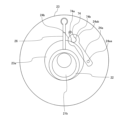
- 2 is a schematic plan view of the hermetic compressor of FIG. 1 , taken along line AA, showing the compression mechanism as viewed in the direction of the arrows.
- 2 is a schematic plan view of the compression mechanism of the hermetic compressor of FIG. 1 taken along line BB, as viewed in the direction of the arrows.
- 2 is an enlarged schematic view of the hermetic compressor of FIG. 1 taken along the arrow C.
- FIG. 3 is a schematic vertical cross-sectional view of the compression mechanism of FIG. 2 taken along the line D-D, showing a cylinder as viewed in the direction of the arrows.
- FIG. 13 is a schematic diagram showing a vertical cross section of a modified example of a hermetic compressor according to an embodiment.
- 2 is a schematic plan view of a discharge valve and an injection check valve projected onto an end surface in a height direction of a cylinder of a hermetic compressor according to an embodiment.
- FIG. 1 is a schematic configuration diagram of a refrigeration cycle device including a hermetic compressor according to an embodiment.
- FIG. 1 is a schematic diagram showing a vertical cross section of a hermetic compressor 100 according to an embodiment.
- FIG. 2 is a schematic plan view of the compression mechanism 20 when the hermetic compressor 100 of FIG. 1 is cut along the line A-A.
- FIG. 3 is a schematic plan view of the compression mechanism 20 when the hermetic compressor 100 of FIG. 1 is cut along the line B-B.
- FIG. 4 is a schematic diagram showing an enlarged view of the C arrow of the hermetic compressor 100 of FIG. 1.
- FIG. 5 is a schematic vertical cross-sectional view of the cylinder 23 when the compression mechanism 20 of FIG. 2 is cut along the line D-D.
- FIG. 6 is a schematic diagram showing a vertical cross section of a modified example of the hermetic compressor 100 according to an embodiment.
- the hermetic compressor 100 is a one-cylinder rotary compressor having one cylinder 23, i.e., a single rotary compressor, as shown in FIG. 1.
- the overall configuration of the hermetic compressor 100, which is a single rotary compressor, is described below.
- the hermetic compressor 100 includes a compression mechanism 20 that compresses refrigerant gas and an electric motor 30 that drives the compression mechanism 20 in a sealed container 10.
- the sealed container 10 is composed of an upper container 11 and a lower container 12, with the compression mechanism 20 housed below the sealed container 10 and the electric motor 30 housed above the sealed container 10.
- the electric motor 30 is composed of a stator 31 and a rotor 32.
- the compression mechanism 20 and the electric motor 30 are connected by a rotating shaft 21 that extends in the vertical direction, and the rotating shaft 21 transmits the rotational motion of the electric motor 30 to the compression mechanism 20, where the refrigerant gas is compressed by the transmitted rotational force and discharged into the sealed container 10.
- the sealed container 10 is filled with compressed high-temperature and high-pressure refrigerant gas, and refrigeration oil is stored in the bottom 10a of the sealed container 10 to lubricate the compression mechanism 20.
- An oil pump (not shown) is provided at the bottom of the rotating shaft 21, and as the rotating shaft 21 rotates, the oil pump draws up the refrigeration oil stored in the bottom 10a of the sealed container 10, and supplies the oil to each sliding part of the compression mechanism 20. This ensures the mechanical lubrication of the compression mechanism 20.
- the rotating shaft 21 is composed of a main shaft portion 21a, an eccentric shaft portion 21b, and a sub-shaft portion 21c, which are formed in the order of main shaft portion 21a, eccentric shaft portion 21b, and sub-shaft portion 21c from top to bottom in the axial direction.
- An electric motor 30 is fixed to the main shaft portion 21a by shrink fitting or press fitting, and a cylindrical rolling piston 22 is fitted slidably into the eccentric shaft portion 21b.
- the compression mechanism 20 includes a rolling piston 22, a cylinder 23, an upper bearing 24, a lower bearing 25, and a vane 26.
- a compression chamber 23a is formed, which is a cylindrical space with both axial ends open.
- the eccentric shaft portion 21b of the rotating shaft 21 that performs eccentric motion inside the compression chamber 23a
- the rolling piston 22 that is fitted into the eccentric shaft portion 21b
- a vane 26 that divides the space formed by the inner circumference of the cylinder 23 and the outer circumference of the rolling piston 22 into a suction side where the refrigerant is sucked in and a compression side where the refrigerant is compressed.
- the cylinder 23 is formed with a vane groove 23c extending radially and penetrating in the axial direction.
- One radial end of the vane groove 23c opens into the compression chamber 23a, and a back pressure chamber 23b is formed on the other radial end.
- a vane 26 is housed in the vane groove 23c.
- the vane 26 reciprocates radially within the vane groove 23c.
- the vane 26 is shaped like a rectangular parallelepiped, with the thickness in the circumferential direction of the compression chamber 23a being smaller than the radial and axial lengths of the compression chamber 23a when attached to the vane groove 23c.
- a vane spring (not shown) is provided in the back pressure chamber 23b of the vane groove 23c.
- the upper bearing 24 has an approximately inverted T-shape in side view, is fitted to the main shaft portion 21a of the rotating shaft 21 to rotatably support the main shaft portion 21a, and closes one axial opening of the compression chamber 23a.
- the lower bearing 25 has an approximately T-shape in side view, is fitted to the counter shaft portion 21c of the rotating shaft 21 to rotatably support the counter shaft portion 21c, and closes the other axial opening of the compression chamber 23a.
- the upper bearing 24 is also provided with a discharge port 24b that discharges the refrigerant gas compressed in the compression chamber 23a to the outside of the compression chamber 23a. As shown in FIG.
- the cylinder 23 is provided with a suction port 23e that draws low-pressure refrigerant gas from outside the sealed container 10 into the compression chamber 23a.
- the cylinder 23 has a discharge notch 23d formed to prevent the refrigerant flow path that communicates with the discharge port 24b from suddenly contracting and bending. This discharge notch 23d is formed by cutting out a part of the inner periphery of the upper end surface of the cylinder 23.
- the upper bearing 24 is provided with a long discharge valve 24a that closes or opens the discharge port 24b.
- one end of the discharge valve 24a is provided with a fixed portion 24aa that is fixed by a fixing member (not shown), and the other end of the discharge valve 24a is provided with a circular head 24ab that closes or opens the discharge port 24b.
- the discharge valve 24a is an opening/closing valve that lifts in the upper bearing 24 and operates as a leaf spring, and the head 24ab closes or opens the discharge port 24b.
- the discharge timing of the high-temperature, high-pressure refrigerant gas discharged from the inside of the compression chamber 23a to the outside of the compression chamber 23a through the discharge port 24b is controlled. That is, the discharge valve 24a closes the discharge port 24b with the head 24ab until the refrigerant gas compressed in the compression chamber 23a of the cylinder 23 reaches a predetermined pressure, and when the pressure reaches or exceeds the predetermined pressure, the discharge port 24b is opened to discharge the high-temperature, high-pressure refrigerant gas to the outside of the compression chamber 23a.
- the upper bearing 24 is also referred to as the blocking member.
- the hermetic compressor 100 may be a rotary compressor having multiple cylinders 23 instead of the single rotary compressor.
- the compression mechanism 20 includes an intermediate plate 28 in addition to the rolling piston 22, cylinder 23, upper bearing 24, lower bearing 25, and vane 26, and the lower bearing 25 is also provided with a discharge port 24b and a discharge valve 24a, just like the upper bearing 24.
- the upper bearing 24 and the lower bearing 25 are also referred to as blocking members.
- each of the two cylinders 23 is provided with a suction port 23e. In other words, one suction port 23e and one discharge port 24b are provided for each cylinder 23.
- the cylinder 23 is formed with an injection horizontal hole 70 extending in the radial direction, and an injection pipe connection part 71 that communicates with the injection horizontal hole 70 is formed on the radial outside of the injection horizontal hole 70.
- the injection pipe connection part 71 is connected to the injection pipe 107.
- the cylinder 23 is also formed with an injection vertical hole 72 extending in the height direction (or axial direction), and the injection vertical hole 72 is formed near the radially inner tip of the injection horizontal hole 70.
- the injection horizontal hole 70 and the injection vertical hole 72 are collectively referred to as the injection hole.
- This injection hole constitutes a part of the injection flow path through which the injection refrigerant that flows from the injection pipe 107 into the compression chamber 23a flows.
- the end of the injection horizontal hole 70 on the compression chamber 23a side is located on the outer periphery side of the cylinder 23 rather than the inner periphery, and is separated from the compression chamber 23a. Therefore, the injection horizontal hole 70 does not communicate with the compression chamber 23a.
- a conical tip hole 70a is formed at the radially inner tip of the injection horizontal hole 70.
- An injection check valve operation groove 77 is formed on one end face of the cylinder 23 in the height direction and on the inner circumferential side of the cylinder 23. The injection check valve operation groove 77 is open so that the inner circumferential side of the cylinder 23 faces the center of the cylinder 23.
- One axial end side of the injection vertical hole 72 communicates with the injection horizontal hole 70, and the other end side communicates with the injection check valve operation groove 77. That is, the injection vertical hole 72 reaches one end face of the cylinder 23 in the height direction.
- the injection vertical hole 72 may communicate with the tip hole 70a. If the injection vertical hole 72 and the tip hole 70a were not in communication, the injection vertical hole 72 would have to be located on the outer periphery of the cylinder 23, which would place restrictions on the placement of the injection check valve 74. However, by communicating the injection vertical hole 72 and the tip hole 70a, the injection vertical hole 72 can be located on the center side of the cylinder 23, which reduces the restrictions on the placement of the injection check valve 74.
- the injection check valve operation groove 77 is provided with a long injection check valve 74 and a long injection check valve lift amount control plate 75. As shown in FIG. 7 described later, one end of the injection check valve 74 is provided with a fixed portion 74a fixed by a fixing member 76 described later, and the other end of the injection check valve 74 is provided with a circular head 74b that closes or opens the injection vertical hole 72.
- the injection check valve 74 is an opening/closing valve that lifts in the injection check valve operation groove 77 and operates as a leaf spring, and closes or opens the injection vertical hole 72 with the head 74b. This controls the injection timing of the injection refrigerant that flows from the injection pipe 107 into the compression chamber 23a through the injection hole.
- the injection check valve lift amount control plate 75 is provided on the opposite side of the injection check valve 74 from the injection vertical hole 72, and is intended to limit the lift amount of the injection check valve 74.
- the injection check valve 74 and the injection check valve lift amount control plate 75 are fixed to one end face in the height direction of the cylinder 23 by a fixing member 76.
- the fixing member 76 is, for example, a bolt, and as shown in FIG. 4, its head 76a protrudes outward from the end face in the height direction of the cylinder 23.
- a storage hole 76b is provided to store the head 76a that protrudes from the lower bearing 25 in the case of a single rotary compressor, or the intermediate plate 28 in the case of a twin rotary compressor. This makes it possible to reduce the depth of the injection check valve operating groove 77, i.e., the axial length, and to effectively discharge the compressed refrigerant.
- the fixing member 76 may be something other than a bolt, for example, a rivet.
- the injection vertical hole 72 is opened and closed by an injection check valve 74, which is a leaf spring.
- the injection check valve 74 is prevented from lifting excessively by an injection check valve lift amount control plate 75.
- An arc-shaped communication portion 73 that connects the injection vertical hole 72 and the compression chamber 23a is formed on the radial inside of the injection check valve operation groove 77. Therefore, the injection check valve operation groove 77 is connected to the compression chamber 23a via the communication portion 73.
- the injection check valve 74 When the pressure inside the compression chamber 23a is lower than the injection pressure, the injected refrigerant pushes up the injection check valve 74 and flows into the compression chamber 23a. This increases the flow rate of the refrigerant compressed and discharged from the cylinder 23 by the amount of the injected refrigerant. Also, when compression inside the compression chamber 23a progresses and the pressure becomes high, the injection check valve 74 seats on the end face in the height direction of the cylinder 23 and closes the injection vertical hole 72, preventing the high-pressure refrigerant from flowing back from the compression chamber 23a to the injection vertical hole 72.
- one injection mechanism is provided for each cylinder 23.
- the same number of compression chambers 23a as the number of cylinders 23 are provided, and an injection mechanism for injecting intermediate pressure refrigerant into each compression chamber 23a is provided.
- the components of the injection mechanism in this embodiment are the suction port 23e, the discharge valve 24a, the discharge port 24b, the injection horizontal hole 70, the tip hole 70a, the injection piping connection part 71, the injection vertical hole 72, the communication part 73, the injection check valve 74, the injection check valve lift amount control plate 75, the fixing member 76, and the injection check valve operation groove 77.
- a discharge muffler 27 is attached to the outside of the upper bearing 24, i.e., on the motor 30 side, so as to cover the upper bearing 24.
- the discharge muffler 27 has a discharge hole (not shown) that connects the space formed by the discharge muffler 27 and the upper bearing 24 to the inside of the sealed container 10. The refrigerant gas discharged from the cylinder 23 through the discharge port 24b is first discharged into the space formed by the discharge muffler 27 and the upper bearing 24, and then discharged from the discharge hole into the sealed container 10.
- a suction muffler 101 is provided next to the sealed container 10 to prevent liquid refrigerant from being directly sucked into the compression chamber 23a of the cylinder 23.
- a hermetic compressor 100 receives a mixture of low-pressure refrigerant gas and liquid refrigerant from an external circuit to which it is connected. If the liquid refrigerant flows into the cylinder 23 and is compressed in the compression mechanism 20, it can cause a breakdown in the compression mechanism 20. Therefore, the suction muffler 101 separates the liquid refrigerant from the refrigerant gas and sends only the refrigerant gas to the compression chamber 23a.
- the suction muffler 101 is connected to the suction port 23e of the cylinder 23 by a suction connecting pipe 110, and the low-pressure refrigerant gas sent from the suction muffler 101 is sucked into the compression chamber 23a via the suction connecting pipe 110.
- the compression mechanism 20 is constructed as described above, and the rotational motion of the rotary shaft 21 rotates the eccentric shaft portion 21b of the rotary shaft 21 in the compression chamber 23a of the cylinder 23.
- the working chamber which is partitioned by the inner periphery of the compression chamber 23a, the outer periphery of the rolling piston 22 fitted in the eccentric shaft portion 21b, and the vane 26, increases or decreases in volume as the rotary shaft 21 rotates.
- the working chamber communicates with the suction port 23e, and low-pressure refrigerant gas is sucked into the working chamber.
- the communication between the working chamber and the suction port 23e is closed, and the refrigerant gas in the working chamber is compressed as the volume of the working chamber decreases.
- the working chamber communicates with the discharge port 24b, and after the refrigerant gas in the working chamber reaches a predetermined pressure, the discharge valve 24a provided in the discharge port 24b opens, and the refrigerant gas is discharged outside the working chamber, i.e., outside the compression chamber 23a, and the high-temperature, high-pressure refrigerant gas is discharged.
- the high-temperature, high-pressure refrigerant gas discharged from the compression chamber 23a through the discharge muffler 27 into the sealed container 10 passes through the motor 30, rises inside the sealed container 10, and is discharged from the discharge pipe 102 provided at the top of the sealed container 10 to the outside of the sealed container 10.
- a refrigerant circuit through which the refrigerant flows is configured outside the sealed container 10, and the discharged refrigerant circulates through the refrigerant circuit and returns to the suction muffler 101.
- one discharge valve 24a and one injection check valve 74 are provided for each cylinder 23.
- the discharge valve 24a is provided on the generally opposite side of the suction port 23e, with respect to the vane 26.
- the injection check valve 74 is provided on the generally opposite side of the suction port 23e, with respect to the vane 26.
- the discharge valve 24a and discharge port 24b are arranged in roughly the same phase as the injection check valve 74 and injection vertical hole 72.
- the phase here refers to the revolution phase of the rolling piston 22.
- the discharge valve 24a and the injection check valve 74 are not in contact with each other.
- the discharge valve 24a is arranged on the upper bearing 24 side
- the injection check valve 74 is arranged on the lower bearing 25 side in the case of a single rotary compressor, and on the intermediate plate 28 side in the case of a twin rotary compressor.
- FIG. 7 is a schematic plan view of the discharge valve 24a and the injection check valve 74 projected onto the end face in the height direction of the cylinder 23 of the hermetic compressor 100 according to the embodiment.
- the two on-off valves are arranged in positions where they interfere with each other.
- the two on-off valves are arranged in positions where they at least partially overlap.
- the layout of the components of the injection mechanism and the like can be expanded, reducing design constraints, and therefore wasted space in the hermetic container 10 can be reduced, resulting in a smaller size and a reduction in manufacturing costs.
- one discharge valve 24a and one injection check valve 74 are provided for each cylinder 23, but this is not limited thereto, and multiple (two or more) discharge valves 24a and injection check valves 74 may be provided for each cylinder 23.
- multiple discharge valves 24a and the multiple injection check valves 74 are projected onto the same plane in the height direction, it is sufficient that at least one of the multiple discharge valves 24a and at least one of the multiple injection check valves 74 are positioned so as to overlap each other.
- the displacement of the hermetic compressor 100 according to the embodiment is approximately 60 cc.
- the longitudinal length of the injection check valve 74 is 10 mm
- the diameter of its head 74b is 6 mm
- the longitudinal length of the discharge valve 24a is 25 mm
- the diameter of its head 24ab is 15 mm.
- the injection refrigerant is compressed and discharged together with the refrigerant from the main circuit that flows in from the suction port 23e. Therefore, since the flow rate of the injection refrigerant is always less than the flow rate of the discharge refrigerant, the size of the injection check valve 74 does not need to be as large as the size of the discharge valve 24a.
- the longitudinal length of the injection check valve 74 is shorter than the longitudinal length of the discharge valve 24a, and the diameter of the head 74b of the injection check valve 74 is smaller than the diameter of the head 24ab of the discharge valve 24a.
- the size of the injection check valve 74 which does not need to be as large as the discharge valve 24a, smaller than the discharge valve 24a, it is possible to reduce wasted space inside the sealed container 10, thereby making it smaller, and thereby reducing manufacturing costs.
- FIG. 8 is a schematic diagram of a refrigeration cycle device 200 equipped with a hermetic compressor 100 according to an embodiment.
- the refrigeration cycle device 200 is, for example, an air conditioner.
- the refrigeration cycle device 200 includes a hermetic compressor 100 equipped with a suction muffler 101 connected to the suction side of the hermetic compressor 100, a flow path switching valve 103 connected to the discharge side of the hermetic compressor 100, an outdoor heat exchanger 104, a pressure reducer 105, and an indoor heat exchanger 106, which are connected in sequence via piping to form a main circuit of a refrigerant circuit in which the refrigerant circulates.
- the refrigerant circuit is provided with an injection piping 107 that branches off from a branch point 107c between the pressure reducer 105 and the indoor heat exchanger 106 in the main circuit and is connected to the compression mechanism 20 of the hermetic compressor 100.
- an injection pressure reducer 107a for adjusting the injection pressure and flow rate, and an injection muffler 107b for rectifying the refrigerant flow are provided in the injection pipe 107.
- the injection pressure reducer 107a may also function as a device for switching the injection ON/OFF, or a separate solenoid valve may be provided in the injection pipe 107 to switch the injection ON/OFF.
- the flow path switching valve 103 is, for example, a four-way valve, and switches between cooling operation and heating operation by switching the direction of the refrigerant flow. Note that the flow path switching valve 103 may be a combination of a two-way valve and a three-way valve instead of a four-way valve.
- the pressure reducer 105 reduces the pressure of the refrigerant to expand it.
- the pressure reducer 105 is, for example, an electronic expansion valve that can adjust the aperture, and by adjusting the aperture, the pressure of the refrigerant flowing into the indoor heat exchanger 106 during cooling operation is controlled, and the pressure of the refrigerant flowing into the outdoor heat exchanger 104 during heating operation is controlled.
- the outdoor heat exchanger 104 functions as an evaporator or a condenser, and exchanges heat between the air and the refrigerant to evaporate and gasify the refrigerant or condense and liquefy the refrigerant.
- the outdoor heat exchanger 104 functions as an evaporator during heating operation, and as a condenser during cooling operation.
- the indoor heat exchanger 106 functions as an evaporator or a condenser, and exchanges heat between the air and the refrigerant to evaporate and gasify the refrigerant or condense and liquefy the refrigerant.
- the indoor heat exchanger 106 functions as a condenser during heating operation and as an evaporator during cooling operation.
- the flow path switching valve 103 is connected to the solid line side in FIG. 8.
- the high-temperature, high-pressure refrigerant compressed by the hermetic compressor 100 flows to the indoor heat exchanger 106, condenses, and liquefies, and is then throttled by the pressure reducer 105 to become a two-phase state of low temperature and low pressure. It then flows to the outdoor heat exchanger 104, evaporates, gasifies, and passes through the flow path switching valve 103 and returns to the hermetic compressor 100 again. That is, the refrigerant circulates as shown by the solid line arrows in FIG. 8.
- the refrigerant exchanges heat with the outside air in the outdoor heat exchanger 104, which is an evaporator, and the refrigerant sent to the outdoor heat exchanger 104 absorbs heat, and the refrigerant that has absorbed heat is sent to the indoor heat exchanger 106, which is a condenser, and exchanges heat with the indoor air to warm the indoor air.
- the valve of the injection pressure reducer 107a is opened to allow the relatively low-temperature refrigerant after heat exchange with the indoor air in the indoor heat exchanger 106 to flow into the injection pipe 107 (see the thick solid arrow in Figure 8). Since the outlet of the injection pipe 107 is connected to the compression mechanism 20 of the hermetic compressor 100, the relatively low-temperature refrigerant that has flowed into the injection pipe 107 flows into the compression mechanism 20 of the hermetic compressor 100 as injection refrigerant.
- the injection refrigerant that has flowed into the compression mechanism 20 is compressed together with the low-pressure refrigerant that has flowed into the suction muffler 101 from the main circuit, and is discharged from the hermetic compressor 100 as high-temperature, high-pressure refrigerant gas.
- the flow path switching valve 103 is connected to the dashed line side in FIG. 8.
- the high-temperature, high-pressure refrigerant compressed by the hermetic compressor 100 flows to the outdoor heat exchanger 104, condenses, and liquefies, and is then throttled by the pressure reducer 105 to become a two-phase state of low temperature and low pressure. It then flows to the indoor heat exchanger 106, evaporates, gasifies, and returns to the flow path switching valve 103 and the hermetic compressor 100.
- the indoor heat exchanger 106 changes from a condenser to an evaporator
- the outdoor heat exchanger 104 changes from an evaporator to a condenser.
- the refrigerant circulates as shown by the dashed arrows in FIG. 8.
- the indoor heat exchanger 106 which is an evaporator, exchanges heat with the indoor air, absorbing heat from the indoor air, i.e., cooling the indoor air, and the refrigerant that has absorbed heat is sent to the outdoor heat exchanger 104, which is a condenser, where it exchanges heat with the outdoor air and releases heat to the outdoor air.
- the hermetic compressor 100 includes a cylinder 23 having a compression chamber 23a for compressing a refrigerant and an injection hole that constitutes part of an injection flow path that supplies refrigerant into the compression chamber 23a, a blocking member that is fixed to both end faces of the cylinder 23 in the height direction and blocks the compression chamber 23a, a discharge valve 24a that is formed in the blocking member fixed to one end face of the cylinder 23 and opens and closes a discharge port 24b that discharges the compressed refrigerant out of the compression chamber 23a, and an injection check valve 74 that opens and closes the injection hole, and the discharge valve 24a and the injection check valve 74 are fixed to different ones of the blocking member fixed to one end face of the cylinder 23 and the blocking member fixed to the other end face of the cylinder 23, and when the discharge valve 24a and the injection check valve 74 are projected onto the same plane in the height direction of the cylinder 23, the discharge valve 24a and the injection check valve 74 are arranged in positions where they at least partially overlap.
- the discharge valve 24a and the injection check valve 74 are projected onto the same plane in the height direction of the cylinder 23, the discharge valve 24a and the injection check valve 74 are arranged in a position where they at least partially overlap.
- the layout options for the components of the injection mechanism are expanded and design constraints are reduced, so that wasted space within the hermetic container 10 can be reduced, allowing for a smaller size, which in turn reduces manufacturing costs.
- the injection hole has an injection horizontal hole 70 extending in the radial direction of the cylinder 23 and an injection vertical hole 72 extending in the height direction of the cylinder 23, and a cone-shaped tip hole 70a is formed on the radial outside of the injection horizontal hole 70, and the injection vertical hole 72 and the tip hole 70a are connected.
- the injection vertical hole 72 and the tip hole 70a are in communication. If the injection vertical hole 72 and the tip hole 70a were not in communication, the injection vertical hole 72 would have to be located on the outer periphery of the cylinder 23, which would restrict the placement of the injection check valve 74. However, by connecting the injection vertical hole 72 and the tip hole 70a, the injection vertical hole 72 can be located on the center side of the cylinder 23, which reduces the restrictions on the placement of the injection check valve 74. As a result, the layout of the components of the injection mechanism can be further expanded, further reducing design restrictions, which further reduces wasted space in the hermetic container 10, thereby enabling further miniaturization and thus further reducing manufacturing costs.
- the injection check valve 74 and the discharge valve 24a are long, the longitudinal length of the injection check valve 74 is shorter than the longitudinal length of the discharge valve 24a, and the diameter of the head 74b of the injection check valve 74 is smaller than the head 24ab of the discharge valve 24a.
- the size of the injection check valve 74 which does not need to be as large as the discharge valve 24a, can be made smaller than the discharge valve 24a, which further reduces wasted space inside the hermetic container 10, thereby enabling further miniaturization and thus further reducing manufacturing costs.
Landscapes
- Engineering & Computer Science (AREA)
- Mechanical Engineering (AREA)
- General Engineering & Computer Science (AREA)
- Applications Or Details Of Rotary Compressors (AREA)
Priority Applications (3)
| Application Number | Priority Date | Filing Date | Title |
|---|---|---|---|
| CN202380092601.7A CN120787281A (zh) | 2023-03-14 | 2023-03-14 | 密闭型压缩机以及制冷循环装置 |
| JP2025506317A JP7770612B2 (ja) | 2023-03-14 | 2023-03-14 | 密閉型圧縮機および冷凍サイクル装置 |
| PCT/JP2023/009872 WO2024189775A1 (ja) | 2023-03-14 | 2023-03-14 | 密閉型圧縮機および冷凍サイクル装置 |
Applications Claiming Priority (1)
| Application Number | Priority Date | Filing Date | Title |
|---|---|---|---|
| PCT/JP2023/009872 WO2024189775A1 (ja) | 2023-03-14 | 2023-03-14 | 密閉型圧縮機および冷凍サイクル装置 |
Publications (1)
| Publication Number | Publication Date |
|---|---|
| WO2024189775A1 true WO2024189775A1 (ja) | 2024-09-19 |
Family
ID=92754694
Family Applications (1)
| Application Number | Title | Priority Date | Filing Date |
|---|---|---|---|
| PCT/JP2023/009872 Ceased WO2024189775A1 (ja) | 2023-03-14 | 2023-03-14 | 密閉型圧縮機および冷凍サイクル装置 |
Country Status (3)
| Country | Link |
|---|---|
| JP (1) | JP7770612B2 (https=) |
| CN (1) | CN120787281A (https=) |
| WO (1) | WO2024189775A1 (https=) |
Cited By (2)
| Publication number | Priority date | Publication date | Assignee | Title |
|---|---|---|---|---|
| WO2026070807A1 (ja) * | 2024-09-26 | 2026-04-02 | ダイキン工業株式会社 | ロータリ圧縮機および冷凍サイクル装置 |
| JP2026059755A (ja) * | 2024-09-26 | 2026-04-07 | ダイキン工業株式会社 | ロータリ圧縮機および冷凍サイクル装置 |
Citations (2)
| Publication number | Priority date | Publication date | Assignee | Title |
|---|---|---|---|---|
| JP2017203451A (ja) * | 2016-05-10 | 2017-11-16 | ダイキン工業株式会社 | 回転式圧縮機 |
| JP2020133407A (ja) * | 2019-02-13 | 2020-08-31 | パナソニックIpマネジメント株式会社 | スクロール圧縮機 |
-
2023
- 2023-03-14 WO PCT/JP2023/009872 patent/WO2024189775A1/ja not_active Ceased
- 2023-03-14 CN CN202380092601.7A patent/CN120787281A/zh active Pending
- 2023-03-14 JP JP2025506317A patent/JP7770612B2/ja active Active
Patent Citations (2)
| Publication number | Priority date | Publication date | Assignee | Title |
|---|---|---|---|---|
| JP2017203451A (ja) * | 2016-05-10 | 2017-11-16 | ダイキン工業株式会社 | 回転式圧縮機 |
| JP2020133407A (ja) * | 2019-02-13 | 2020-08-31 | パナソニックIpマネジメント株式会社 | スクロール圧縮機 |
Cited By (4)
| Publication number | Priority date | Publication date | Assignee | Title |
|---|---|---|---|---|
| WO2026070807A1 (ja) * | 2024-09-26 | 2026-04-02 | ダイキン工業株式会社 | ロータリ圧縮機および冷凍サイクル装置 |
| JP2026059755A (ja) * | 2024-09-26 | 2026-04-07 | ダイキン工業株式会社 | ロータリ圧縮機および冷凍サイクル装置 |
| JP2026059756A (ja) * | 2024-09-26 | 2026-04-07 | ダイキン工業株式会社 | ロータリ圧縮機および冷凍サイクル装置 |
| JP2026059758A (ja) * | 2024-09-26 | 2026-04-07 | ダイキン工業株式会社 | ロータリ圧縮機および冷凍サイクル装置 |
Also Published As
| Publication number | Publication date |
|---|---|
| JP7770612B2 (ja) | 2025-11-14 |
| JPWO2024189775A1 (https=) | 2024-09-19 |
| CN120787281A (zh) | 2025-10-14 |
Similar Documents
| Publication | Publication Date | Title |
|---|---|---|
| WO2024189777A1 (ja) | 密閉型圧縮機および冷凍サイクル装置 | |
| AU2005240929B2 (en) | Rotary compressor | |
| JP5760836B2 (ja) | ロータリ圧縮機 | |
| JP7770612B2 (ja) | 密閉型圧縮機および冷凍サイクル装置 | |
| JP2008303858A (ja) | スクロール圧縮機 | |
| US7618245B2 (en) | Fluid machine | |
| JP3764261B2 (ja) | スクロール圧縮機 | |
| JP4989269B2 (ja) | 流体機械および冷凍サイクル装置 | |
| US12492699B2 (en) | Compressor and air conditioner | |
| JP7837467B2 (ja) | 密閉型圧縮機および冷凍サイクル装置 | |
| JP3087665B2 (ja) | ロータリー圧縮機 | |
| US12055325B2 (en) | Rotary compressor and home appliance including the same | |
| WO2021214913A1 (ja) | 圧縮機 | |
| JPH0681786A (ja) | 2段圧縮形回転式圧縮機 | |
| JP7745664B2 (ja) | 圧縮機及び該圧縮機を備えた冷凍サイクル装置 | |
| JP3883837B2 (ja) | ロータリコンプレッサ | |
| WO2021149180A1 (ja) | 圧縮機 | |
| CN204627985U (zh) | 旋转式压缩机及具有其的冷冻装置 | |
| KR101587168B1 (ko) | 로터리 압축기 | |
| WO2022149225A1 (ja) | 圧縮機 | |
| WO2023187909A1 (ja) | 密閉型圧縮機および冷凍サイクル装置 | |
| WO2025057327A1 (ja) | スクロール圧縮機、及び冷凍サイクル装置 | |
| WO2026058422A1 (ja) | スクリュー圧縮機及び冷凍サイクル装置 | |
| KR20240117690A (ko) | 트레판을 구비한 로터리 압축기 및 이를 포함하는 가전기기 | |
| WO2023170901A1 (ja) | スクロール圧縮機および冷凍サイクル装置 |
Legal Events
| Date | Code | Title | Description |
|---|---|---|---|
| 121 | Ep: the epo has been informed by wipo that ep was designated in this application |
Ref document number: 23927396 Country of ref document: EP Kind code of ref document: A1 |
|
| WWE | Wipo information: entry into national phase |
Ref document number: 2025506317 Country of ref document: JP |
|
| WWE | Wipo information: entry into national phase |
Ref document number: 202380092601.7 Country of ref document: CN |
|
| WWP | Wipo information: published in national office |
Ref document number: 202380092601.7 Country of ref document: CN |
|
| NENP | Non-entry into the national phase |
Ref country code: DE |
|
| 122 | Ep: pct application non-entry in european phase |
Ref document number: 23927396 Country of ref document: EP Kind code of ref document: A1 |