WO2024185695A1 - ノズルモジュール、3dプリンタおよび造形物の製造方法 - Google Patents
ノズルモジュール、3dプリンタおよび造形物の製造方法 Download PDFInfo
- Publication number
- WO2024185695A1 WO2024185695A1 PCT/JP2024/007790 JP2024007790W WO2024185695A1 WO 2024185695 A1 WO2024185695 A1 WO 2024185695A1 JP 2024007790 W JP2024007790 W JP 2024007790W WO 2024185695 A1 WO2024185695 A1 WO 2024185695A1
- Authority
- WO
- WIPO (PCT)
- Prior art keywords
- guide rail
- axis guide
- axis
- nozzle
- drive module
- Prior art date
- Legal status (The legal status is an assumption and is not a legal conclusion. Google has not performed a legal analysis and makes no representation as to the accuracy of the status listed.)
- Ceased
Links
Images


Classifications
-
- B—PERFORMING OPERATIONS; TRANSPORTING
- B05—SPRAYING OR ATOMISING IN GENERAL; APPLYING FLUENT MATERIALS TO SURFACES, IN GENERAL
- B05B—SPRAYING APPARATUS; ATOMISING APPARATUS; NOZZLES
- B05B15/00—Details of spraying plant or spraying apparatus not otherwise provided for; Accessories
- B05B15/14—Arrangements for preventing or controlling structural damage to spraying apparatus or its outlets, e.g. for breaking at desired places; Arrangements for handling or replacing damaged parts
- B05B15/16—Arrangements for preventing or controlling structural damage to spraying apparatus or its outlets, e.g. for breaking at desired places; Arrangements for handling or replacing damaged parts for preventing non-intended contact between spray heads or nozzles and foreign bodies, e.g. nozzle guards
-
- B—PERFORMING OPERATIONS; TRANSPORTING
- B28—WORKING CEMENT, CLAY, OR STONE
- B28B—SHAPING CLAY OR OTHER CERAMIC COMPOSITIONS; SHAPING SLAG; SHAPING MIXTURES CONTAINING CEMENTITIOUS MATERIAL, e.g. PLASTER
- B28B1/00—Producing shaped prefabricated articles from the material
- B28B1/30—Producing shaped prefabricated articles from the material by applying the material on to a core or other moulding surface to form a layer thereon
-
- B—PERFORMING OPERATIONS; TRANSPORTING
- B29—WORKING OF PLASTICS; WORKING OF SUBSTANCES IN A PLASTIC STATE IN GENERAL
- B29C—SHAPING OR JOINING OF PLASTICS; SHAPING OF MATERIAL IN A PLASTIC STATE, NOT OTHERWISE PROVIDED FOR; AFTER-TREATMENT OF THE SHAPED PRODUCTS, e.g. REPAIRING
- B29C64/00—Additive manufacturing, i.e. manufacturing of three-dimensional [3D] objects by additive deposition, additive agglomeration or additive layering, e.g. by 3D printing, stereolithography or selective laser sintering
- B29C64/20—Apparatus for additive manufacturing; Details thereof or accessories therefor
- B29C64/205—Means for applying layers
- B29C64/209—Heads; Nozzles
-
- B—PERFORMING OPERATIONS; TRANSPORTING
- B29—WORKING OF PLASTICS; WORKING OF SUBSTANCES IN A PLASTIC STATE IN GENERAL
- B29C—SHAPING OR JOINING OF PLASTICS; SHAPING OF MATERIAL IN A PLASTIC STATE, NOT OTHERWISE PROVIDED FOR; AFTER-TREATMENT OF THE SHAPED PRODUCTS, e.g. REPAIRING
- B29C64/00—Additive manufacturing, i.e. manufacturing of three-dimensional [3D] objects by additive deposition, additive agglomeration or additive layering, e.g. by 3D printing, stereolithography or selective laser sintering
- B29C64/20—Apparatus for additive manufacturing; Details thereof or accessories therefor
- B29C64/227—Driving means
- B29C64/236—Driving means for motion in a direction within the plane of a layer
-
- B—PERFORMING OPERATIONS; TRANSPORTING
- B33—ADDITIVE MANUFACTURING TECHNOLOGY
- B33Y—ADDITIVE MANUFACTURING, i.e. MANUFACTURING OF THREE-DIMENSIONAL [3D] OBJECTS BY ADDITIVE DEPOSITION, ADDITIVE AGGLOMERATION OR ADDITIVE LAYERING, e.g. BY 3D PRINTING, STEREOLITHOGRAPHY OR SELECTIVE LASER SINTERING
- B33Y10/00—Processes of additive manufacturing
-
- B—PERFORMING OPERATIONS; TRANSPORTING
- B33—ADDITIVE MANUFACTURING TECHNOLOGY
- B33Y—ADDITIVE MANUFACTURING, i.e. MANUFACTURING OF THREE-DIMENSIONAL [3D] OBJECTS BY ADDITIVE DEPOSITION, ADDITIVE AGGLOMERATION OR ADDITIVE LAYERING, e.g. BY 3D PRINTING, STEREOLITHOGRAPHY OR SELECTIVE LASER SINTERING
- B33Y30/00—Apparatus for additive manufacturing; Details thereof or accessories therefor
-
- B—PERFORMING OPERATIONS; TRANSPORTING
- B33—ADDITIVE MANUFACTURING TECHNOLOGY
- B33Y—ADDITIVE MANUFACTURING, i.e. MANUFACTURING OF THREE-DIMENSIONAL [3D] OBJECTS BY ADDITIVE DEPOSITION, ADDITIVE AGGLOMERATION OR ADDITIVE LAYERING, e.g. BY 3D PRINTING, STEREOLITHOGRAPHY OR SELECTIVE LASER SINTERING
- B33Y50/00—Data acquisition or data processing for additive manufacturing
- B33Y50/02—Data acquisition or data processing for additive manufacturing for controlling or regulating additive manufacturing processes
Definitions
- the present invention relates to a nozzle module, a 3D printer, and a method for manufacturing a molded object.
- 3D printers are used for a variety of purposes because they can easily create objects with complex shapes.
- Some 3D printers are equipped with a frame consisting of a pair of upper and lower rectangular frames and four supports connecting the corners of the upper and lower frames, a nozzle placed within the frame, and a drive unit that is installed on the frame and drives the nozzle up and down, left and right, and front and back within the frame.
- the frame serves as a workspace, and some 3D printers eject material from the nozzle to print the object within the workspace.
- a portable 3D printer could be assembled and used at the construction site to produce concrete objects at the construction site.
- conventional 3D printers are not suitable for use at construction sites because they are not portable or are not suitable for assembly at the construction site, or even if they can be assembled at the construction site, there is a possibility that a good object will not be obtained.
- the present invention aims to provide a 3D printer suitable for use on construction sites, a nozzle module suitable for a 3D printer, and a manufacturing method for objects capable of printing high-quality objects.
- the nozzle module of the present invention comprises a running body capable of running along a movable rail that can move up and down, a nozzle that is held by the running body and capable of discharging a fluid, and a detection means for detecting a load that moves the nozzle upward relative to the running body or the upward movement of the nozzle relative to the running body.
- the 3D printer of the present invention includes a frame including multiple support columns extending in the vertical direction, a movable rail that can move in the vertical direction relative to the frame, and a drive device that includes the nozzle module and drives the nozzle within the space surrounded by the support columns of the frame.
- the manufacturing method of the present invention for a molded object includes a frame including a plurality of supports extending in the vertical direction, a nozzle for discharging a fluid, a movable rail that can move in the vertical direction relative to the frame, a running body that can run along the movable rail, a nozzle that is held on the running body and can discharge a fluid, and a nozzle module that has a load that moves the nozzle upward relative to the running body or a detection means that detects the upward movement of the nozzle relative to the running body, and uses a 3D printer equipped with a drive device that drives the nozzle within a space surrounded by the supports of the frame, and prints a molded object by discharging a cement-based mixed fluid from the nozzle.
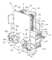
- FIG. 1 is a perspective view of a 3D printer according to one embodiment.
- FIG. 2 is a perspective view of a Y-axis drive module according to an embodiment, seen from above and in front.
- 1 is a perspective view of an X-axis guide rail and a Y-axis drive module according to an embodiment, seen from above on the front side.
- FIG. FIG. 2 is a perspective view of one end of an X-axis guide rail in one embodiment.
- 1 is a perspective view of one end of an X-axis guide rail and a Y-axis drive module according to an embodiment, as viewed from the bottom rear side.
- FIG. 1 is a perspective view of one end of an X-axis guide rail and a Y-axis drive module according to an embodiment, as viewed from above the front.
- FIG. 1 is a diagram showing one end of an X-axis guide rail and a traveling device in a traveling body of a Y-axis drive module in one embodiment.
- FIG. 1 is a schematic diagram showing one end of an X-axis guide rail and a Y-axis drive module as viewed from the side in one embodiment.
- FIG. 4 is a side view of the holding fitting in the mounting fitting.
- FIG. 4 is a cross-sectional view of an adjustment fitting in the mounting fitting.
- FIG. 11 is a perspective view of the other end of the X-axis guide rail and the Y-axis drive module according to the embodiment, as viewed from above the front.
- FIG. FIG. 2 is a perspective view of a Z-axis drive module according to an embodiment, seen from above and at the front.
- FIG. 2 is a perspective view of a Z-axis drive module according to an embodiment, seen from above on the rear side.
- FIG. 2 is a diagram showing a traveling device in a traveling body of a Z-axis drive module according to an embodiment.
- 11 is a schematic diagram of a Y-axis drive module according to a first modified example of the embodiment, as viewed from the side.
- FIG. 13 is a schematic diagram of a Y-axis drive module according to a second modified example of the embodiment, as viewed from the side.
- 13 is a schematic side view of a Y-axis drive module according to a third modified example of the embodiment;
- FIG. 13 is a perspective view of an X-axis drive module according to a fourth modified example of the embodiment, as viewed from above on the rear side.
- FIG. 2 is a perspective view of an X-axis drive module according to an embodiment, seen from above and at the front.
- FIG. 2 is a perspective view of the X-axis drive module according to the embodiment, seen from above on the rear side.
- FIG. 2 is a perspective view of the X-axis drive module according to the embodiment, seen from the lower front side.
- FIG. 11 is a diagram showing an example of a procedure for a zero point adjustment process of a 3D printer according to an embodiment.
- FIG. FIG. 13 is a perspective view of a 3D printer according to another embodiment.
- FIG. 11 is a perspective view of a first running body according to another embodiment, as viewed from above the front side.
- FIG. 11 is a perspective view of a first running body according to another embodiment, as viewed from above the rear side.
- FIG. 11 is a perspective view of a second running body according to another embodiment, as viewed from above the rear side.
- FIG. 11 is a perspective view of a second guide frame on which a support device according to another embodiment is installed.
- FIG. 11 is a partially enlarged perspective view of a second guide frame on which a support piece is installed in another embodiment.
- the 3D printer 1 in this embodiment is equipped with a frame 2 including a support composed of multiple Z-axis guide rails 21 extending in the vertical direction, a nozzle 3 that ejects fluid, a drive unit 4 that drives the nozzle 3 within a workspace W surrounded by the Z-axis guide rails 21 of the frame 2, a pump 6 that supplies the fluid ejected from the nozzle 3 to the nozzle 3 through a flexible hose H, and a controller 7 that controls the drive unit 4 and the pump 6.
- a frame 2 including a support composed of multiple Z-axis guide rails 21 extending in the vertical direction, a nozzle 3 that ejects fluid, a drive unit 4 that drives the nozzle 3 within a workspace W surrounded by the Z-axis guide rails 21 of the frame 2, a pump 6 that supplies the fluid ejected from the nozzle 3 to the nozzle 3 through a flexible hose H, and a controller 7 that controls the drive unit 4 and the pump 6.
- the frame 2 has a rectangular upper frame 22 and a lower frame 23 that face each other in the vertical direction, and four Z-axis guide rails 21 that extend in the vertical direction and connect the upper frame 22 and the lower frame 23.
- the upper frame 22 and the lower frame 23 are both formed of four square frame materials assembled into a rectangle via the Z-axis guide rails 21.
- the Z-axis guide rails 21 are formed of frame material with an L-shaped cross section and function as a guide rail for the Z-axis drive module 41 described later, as well as a support that supports the upper frame 22.
- casters 24 and outriggers 25 are provided at each of the four corners of the bottom end of the frame 2, allowing the 3D printer 1 to be easily moved, and the 3D printer 1 can be fixed to the ground by extending the outriggers 25 and raising the casters 24 off the ground.
- the frame 2 is thus constructed by assembling square frame materials in a lattice pattern, and has the strength to support the nozzle 3, flexible hose H, and drive unit 4 described below.
- the frame 2 is constructed as described above, it is sufficient that the frame 2 is constructed to include a plurality of Z-axis guide rails 21 and be able to stand on the ground, and the upper frame 22 or lower frame 23 may be omitted if not required.
- the upper frame 22 and lower frame 23 are not limited to being rectangular, and may be other shapes such as L-shaped, polygonal, circular, or elliptical.
- the frame materials constituting the Z-axis guide rails 21, the upper frame 22, and the lower frame 23 may be formed from frame materials other than square frame materials or pipes.
- the nozzle 3 is provided within the workspace W, which is the space surrounded by the frame 2, and is connected to a flexible hose H, allowing it to move up and down, left and right, and back and forth within the workspace W.
- the pump 6 includes a hopper 6a and a pump module body 6b that discharges a cement-based mixed fluid from a discharge port as a fluid put into the hopper 6a, and supplies the fluid to the nozzle 3 through a flexible hose H that connects the discharge port to the nozzle 3.
- the 3D printer 1 of this embodiment is an architectural 3D printer used for architectural purposes, and therefore produces objects to be used in architecture using the fluid discharged from the nozzle 3 as a cement-based mixed fluid.
- the uses of the 3D printer 1 are not limited to architectural purposes, and the fluid discharged from the nozzle 3 may be any fluid capable of producing an appropriate object depending on the use of the 3D printer 1.
- the nozzle 3 is moved within the workspace W by the drive device 4, and continuously or intermittently discharges the cement-based mixed fluid supplied from the pump 6 through the flexible hose H along the movement trajectory.
- the nozzle 3 discharges the cement-based mixed fluid from the discharge port when the pump 6 is driven, and stops discharging the cement-based mixed fluid when the pump 6 stops. In this way, the discharge of the cement-based mixed fluid from the nozzle 3 can be switched on and off by turning the pump 6 on and off.
- the nozzle 3 may be provided with a valve at the discharge port to switch whether or not to discharge the cement-based mixed fluid in addition to turning the pump 6 on and off.
- the pump 6 may be a pump mixer capable of mixing and discharging the cement-based mixed fluid.
- the cementitious mixed fluid fed into the pump 6 is produced by an agitator (not shown).
- the cementitious mixed fluid produced by the agitator may be any of a variety of cementitious mixed fluids, such as mortar, cement paste, or concrete, and is preferably self-supporting and fast-hardening. If the cementitious mixed fluid has high thixotropy, the 3D printer 1 can eject the mixed fluid well, and the mixed fluid can be self-supporting after ejection. Therefore, it is preferable for the cementitious mixed fluid to have high thixotropy.
- cementitious fluid mixture In order to obtain rapid hardening properties in a cementitious fluid mixture, it is sufficient to add an early hardening agent, a cement hardening accelerator, and a quick-setting agent, and it is also preferable to mix a set retarder such as an oxycarboxylic acid such as citric acid, tartaric acid, gluconic acid, or malic acid, or a salt thereof, into the powder containing cement so that the cementitious fluid mixture can maintain a certain level of fluidity from the time it is produced by the agitator until it is discharged from the 3D printer 1.
- a set retarder such as an oxycarboxylic acid such as citric acid, tartaric acid, gluconic acid, or malic acid, or a salt thereof
- short and long needle-shaped synthetic resin fibers such as polypropylene fibers, polyvinyl alcohol fibers, polyester fibers, and aramid fibers, as well as inorganic fibers such as steel fibers, glass fibers, silica fibers, ceramic fibers, and carbon fibers can be mixed into the cement as reinforcing materials.
- the flexible hose H is flexible and connects the discharge port of the pump 6 to the nozzle 3, supplying the cement-based mixed fluid discharged from the pump 6 to the nozzle 3.
- the flexible hose H is supported midway by a hose holder 13 attached to the upper frame 22 of the frame 2, and is designed to enter the workspace W through the upper part of the upper frame 22, with its tip connected to the nozzle 3 and its base connected to the pump 6.
- the hose holder 13 can run on the corner frame material on one side of the upper frame 22, and is equipped with a roller that supports the flexible hose H from below and guide rollers arranged on both sides of the flexible hose H, allowing the flexible hose H to be smoothly drawn into the workspace W and sent out to the outside of the workspace as the nozzle 3 moves.
- the drive device 4 includes four Z-axis guide rails 21 that stand upright in the vertical direction, four Z-axis drive modules 41 that are attached to the Z-axis guide rails 21 and can move up and down along the Z-axis guide rails 21, two Y-axis guide rails 42 that are horizontally stretched between the Z-axis drive modules 41, 41 attached to the two Z-axis guide rails 21 on the left side of the frame 2 and between the Z-axis drive modules 41, 41 attached to the two Z-axis guide rails 21 on the right side of the frame 2, two Y-axis drive modules 43 that are attached to the Y-axis guide rails 42 and can move forward and backward along the Y-axis guide rails 42, an X-axis guide rail 44 that is horizontally stretched between the Y-axis drive modules 43, 43 attached to the Y-axis guide rails 42, and an X-axis drive module 45 that is attached to the X-axis guide rails 44 and
- the Z-axis drive module 41 is self-propelled and can move up and down relative to the Z-axis guide rail 21.
- the Y-axis guide rail 42 is made of a square frame material, just like the Z-axis guide rail 21, and is horizontally spanned between the Z-axis drive modules 41, 41 attached to the two Z-axis guide rails 21 on the left side in FIG. 1, and between the Z-axis drive modules 41, 41 attached to the two Z-axis guide rails 21 on the right side in FIG. 1.
- the Y-axis guide rails 42, 42 are attached to the frame 2 at the same height and in parallel via the Z-axis drive modules 41, 41. Therefore, when each Z-axis drive module 41 is moved vertically relative to the Z-axis guide rail 21, the Y-axis guide rails 42, 42 move vertically in sync along the Z-axis guide rail 21.
- the Y-axis drive module 43 can move independently in the forward and backward directions relative to the Y-axis guide rail 42.
- the two Y-axis drive modules 43 are controlled by the controller 7 and move in the forward and backward directions relative to the Y-axis guide rail 42 in synchronization.
- the X-axis guide rail 44 is formed of a square frame material like the Z-axis guide rail 21, and is horizontally spanned between the Y-axis drive modules 43, 43 attached to the two Y-axis guide rails 42.
- the X-axis guide rails 44 are attached to the frame 2 at the same height and in parallel via the Y-axis drive modules 43. Therefore, when each Y-axis drive module 43, 43 is moved in the front-back direction relative to the Y-axis guide rail 42, the X-axis guide rail 44 moves in the front-back direction along the Y-axis guide rail 42 without tilting horizontally relative to the Y-axis guide rail 42.
- the X-axis drive module 45 holds the nozzle 3, and can move independently together with the nozzle 3 in the left-right direction relative to the X-axis guide rail 44.
- the controller 7 controls the pump 6 and each of the drive modules 41, 43, and 45 in the drive device 4.
- the controller 7 is configured with, for example, a well-known computer equipped with a CPU (Central Processing Unit), memory, auxiliary storage device, interface, and a bus that connects these devices so that they can communicate with each other, and a driver that supplies pulse signals and currents to the pump 6 and each of the drive modules 41, 43, and 45 according to the command when it receives a command from the computer via the interface.
- a CPU Central Processing Unit
- each of the drive modules 41, 43, and 45 has a sensor for determining its own position relative to each of the guide rails 21, 42, and 44 to which it is attached, and the controller 7 can obtain position information from these sensors to determine the position of the nozzle 3.
- the sensor for determining the position of each drive module 41, 43, 45 may be, for example, a distance sensor, or a sensor that detects the number of rotations associated with the motor provided in each drive module 41, 43, 45 in the case where the movement distance of the nozzle 3 per rotation of the motor provided in each drive module 41, 43, 45 is determined, but other sensors may also be used.
- the CPU executes a 3D printing process, divides data modeling the three-dimensional shape of the object to be produced into thin vertical layers, obtains two-dimensional data for each divided layer, and determines the printing path for each layer to create a printing procedure.
- the controller 7 then drives each drive module 41, 43, 45 to move the nozzle 3 according to the obtained printing procedure, while driving the pump 6 to eject the cement-based mixed fluid from the nozzle 3 at a predetermined flow rate.
- the 3D printer 1 prints each divided layer without using a formwork while ejecting the cement-based mixed fluid from the nozzle 3, and can create the object when printing of all layers is completed.
- the Y-axis drive module 43 and the X-axis drive module 45 have in common the fact that they each include a running body D consisting of a main body 50 and a running device 51, a guide roller 50d as a guide provided on the running body D, and a biasing member 50f that biases the guide roller 50d toward the side of the Y-axis guide rail 42 to abut against the side of the Y-axis guide rail 42.
- the Y-axis drive module 43 will be described in detail with respect to the common parts, and the detailed configuration of the X-axis drive module 45 will not be described here as it would be redundant.
- the Y-axis guide rail 42 is hollow and has a substantially rectangular cross section, and includes a pair of first side surfaces 42a, 42b that face each other in parallel in the vertical direction, and a pair of second side surfaces 42c, 42d that face each other in parallel in the horizontal direction and are perpendicular to the first side surfaces 42a, 42b, respectively, and further includes a running groove 42a1 formed along the extension direction of the upper first side surface 42a.
- a rack belt 57 formed of a toothed belt is laid along the extension direction of the running groove 42a1.
- the Y-axis drive module 43 is equipped with a running body D consisting of a main body 50 and a running device 51, and is capable of self-propelling along the extension direction on the Y-axis guide rail 42.
- the main body 50 is equipped with a pair of plates 50a, 50b that are arranged on the sides of the second side surfaces 42c, 42d of the Y-axis guide rail 42, facing each other across the Y-axis guide rail 42 and connected to each other, and a roller holding plate 50c that is attached to one plate 50a at a distance from the other plate 50b on the opposite side.
- the Y-axis drive module 43 also includes a guide roller 50d that is attached to the roller holding plate 50c via a biasing member 50f as a guide, and a pair of second guide rollers 50e, 50e that are rotatably mounted on the other plate 50b and abut against the second side 42d opposite the second side 42c against which the guide roller 50d of the Y-axis guide rail 42 abuts, and the lower first side 42b.
- the biasing member 50f has a base end attached to the roller holding plate 50c, and is equipped with a pair of telescopic tubes 50f1 that are equipped with an inner tube and an outer tube and can be expanded and contracted by relative axial movement of the inner tube and the outer tube, and an elastic body such as a spring (not shown) housed inside the telescopic tube 50f1, and constantly generates a resilient force in the extension direction.
- the biasing member 50f may be an air spring in which gas is sealed inside the telescopic tube 50f1, or it may be a member that can bias the guide roller 50d toward the Y-axis guide rail 42 even if it does not have a telescopic tube 50f1.
- the guide roller 50d is mounted on a roller holding piece 50f2 attached to the tip of the telescopic tube 50f1 of the biasing member 50f so as to be rotatable in the horizontal direction, and faces the vicinity of the lower end of one of the second sides 42c, 42d of the Y-axis guide rail 42, and is pressed against the second side 42c by the biasing member 50f.
- the second guide rollers 50e are attached to the plate 50b so as to be rotatable around an axis inclined at 45 degrees relative to the other plate 50b when viewed from the axial direction of the Y-axis guide rail 42, and each has a V-groove so that it can abut against the first side surface 42b and one of the second side surfaces 42d of the Y-axis guide rail 42 below.
- the second guide rollers 50e abut against the first side surface 42b of the Y-axis guide rail 42 below and the second side surface 42d opposite to the second side surface 42c with which the guide rollers 50d abut, by inserting the lower corner of the Y-axis guide rail 42 into the V-groove.
- the two second guide rollers 50e abut against the first side surface 42b of the Y-axis guide rail 42 below and the second side surface 42d of the Y-axis guide rail 42 at an interval in the extension direction of the Y-axis guide rail 42.
- the second guide roller 50e is connected to the other plate 50b via a hinge (not shown) and is attached to the plate 50b via a roller retaining piece 53 that can rotate around an axis along the extension direction of the Y-axis guide rail 42.
- the side plate 50b has a protruding piece 50b1 that protrudes from the side in the extension direction of the Y-axis guide rail 42 toward the side opposite the Y-axis guide rail and faces the roller holding piece 53, and a pin 54a that can be inserted and removed from a hole not shown in the figure provided in the protruding piece 50b1, and a pin member 54 that can hold the pin 54a in a state where the pin 54a is inserted into the hole and a state where it is pulled out from the hole.
- the posture of the second guide roller 50e can be changed to a running posture in which the second guide roller 50e is positioned to abut against the Y-axis guide rail 42, and a release posture in which the second guide roller 50e is released from the Y-axis guide rail 42 and is positioned so that the second guide roller 50e does not overlap the Y-axis guide rail 42 when viewed from above.
- the roller holding piece 53 has a hole 53a that faces the hole provided in the protruding piece 50b1 when the roller holding piece 53 is in the running position, and a notch 53b that faces the hole provided in the protruding piece 50b1 when the roller holding piece 53 is in the released position. Therefore, when the pin 54a of the pin member 54 is inserted into the hole 53a when the roller holding piece 53 is in the running position, the second guide roller 50e can be fixed in the running position, and when the pin 54a of the pin member 54 is inserted into the notch 53b when the roller holding piece 53 is in the released position, the second guide roller 50e can be fixed in the released position.
- the second guide roller 50e can be selectively fixed in the running position and the released position, and the pin member 54 functions as a holding member that holds the second guide roller 50e in the running position and the released position.
- the pin member 54 is biased by an internal spring so that the pin 54a always protrudes toward the roller holding piece 53 through the hole in the protruding piece 50b1, so that the second guide roller 50e can be held in the running position and the released position by the pin 54a. If the pin member 54 does not have a spring, it is preferable that the pin member 54 has a holding mechanism that can hold the pin 54a protruding into the hole 53a and the notch 53b of the roller holding piece 53.
- the rollers 51a, 51a are rotatably held relative to the plate 50a and can run in the running groove 42a1 provided in the Y-axis guide rail 42.
- the left support wheel 51b of the two support wheels 51b, 51b is rotatably attached to the shaft 55b of the support wheel holding bracket 55, which has a base 55a and a shaft 55b attached to the base 55a.
- the support wheel holding bracket 55 is attached to one plate 50a by a bolt 49 that is inserted into a long hole 50j provided in one plate 50a along the vertical direction and screws into the base 55a.
- the support wheel holding bracket 55 can be moved in the vertical direction depending on the mounting position of the bolt 49 relative to the long hole 50j, which allows the installation position of the support wheel 51b relative to the plate 50a to be changed in the vertical direction and the support wheel 51b can be fixed to the plate 50a.
- the driving wheel 51c has many teeth on its outer circumference and is rotatably attached to one of the plates 50a.
- the rotation shaft (not shown) of the driving wheel 51c passes through the plate 50a and extends toward the roller holding plate 50c, and is connected to a pulley 51f that is arranged between the plate 50a and the roller holding plate 50c. Therefore, the driving wheel 51c rotates in synchronization with the pulley 51f.
- the toothed belt 51d is annular, and is wound with its teeth facing outward below the rollers 51a, 51a, above one of the support wheels 51b, below the driving wheel 51c, and above the other support wheel 51b. Therefore, the driving wheel 51c engages with the teeth on the outer circumference of the toothed belt 51d.
- the left support wheel 51b can be moved up and down closer to the rollers 51a, 51a and the drive wheel 51c, and by adjusting the installation position of the left support wheel 51b, it is possible to provide the toothed belt 51d with an appropriate tension suitable for driving.
- the motor 51e is attached to the roller holding plate 50c, and a sprocket 51e1 attached to the outer periphery of the rotor shaft protrudes between one plate 50a and the roller holding plate 50c through a hole (not shown) provided in the roller holding plate 50c.
- a toothed belt 51g is wound around the outer periphery of the sprocket 51e1 and pulley 51f, and when the motor 51e is driven, the drive wheel 51c rotates together with the pulley 51f, and the toothed belt 51d wound around the rollers 51a, 51a, the support wheels 51b, 51b, and the drive wheel 51c is also driven to rotate.
- the rectangular Y-axis guide rail 42 is sandwiched between the rollers 51a, 51a and the second guide roller 50e in the vertical direction perpendicular to the first side surfaces 42a, 42b, and the rollers 51a, 51a apply a load to the toothed belt 51d between the rollers 51a, 51a and the bottom of the running groove 42a1 and the rack belt 57 laid on the bottom of the running groove 42a1 of the first side surface 42a of the Y-axis guide rail 42, and press the toothed belt 51d between the rollers 51a, 51a and the rack belt 57 laid on the bottom of the running groove 42a1 of the first side surface 42a of the Y-axis guide rail 42.
- the toothed belt 51d and the rack belt 57 have elasticity, they are elastically deformed by the pressure from the rollers 51a, 51a, and the teeth of both can be meshed without rattling, and when the motor 51e is driven, the Y-axis drive module 43 can run on the Y-axis guide rail 42 without rattling in the extension direction of the rack belt 57.
- the Y-axis drive module 43 has two rollers 51a, 51a, but it is sufficient to have at least one roller 51a.
- the Y-axis drive module 43 has two or more rollers 51a, 51a arranged along the running direction, it is advantageous in that it can run on the Y-axis guide rail 42 without tilting forward or backward in the running direction.
- the guide roller 50d and the second guide roller 50e sandwich the rectangular Y-axis guide rail 42 in the left-right direction perpendicular to the second side surfaces 42c and 42d, and the guide roller 50d is biased by the biasing member 50f and pressed against the Y-axis guide rail 42, so that the Y-axis guide rail 42 is held while applying a load in the left-right direction.
- the Y-axis drive module 43 of this embodiment sandwiches the Y-axis guide rail 42 from above, below, and to the left and right by the rollers 51a, the guide rollers 50d, and the second guide rollers 50e, so that it can move in the extension direction without rattling relative to the Y-axis guide rail 42.
- the guide roller 50d is biased by the biasing member 50f and abuts against the second side surface 42c of the Y-axis guide rail 42, even if the guide roller 50d or the second guide roller 50e of the second side surfaces 42c, 42d of the Y-axis guide rail 42 runs over foreign matter such as mud or sand that has adhered to the portion where it runs, the biasing member 50f contracts and the guide roller 50d or the second guide roller 50e can easily get over the foreign matter, so that the Y-axis drive module 43 can move smoothly along the Y-axis guide rail 42 with the foreign matter attached, without rattling or stopping.
- the running device 51 in the Y-axis drive module 43 of this embodiment uses an elastic toothed belt 51d and an elastic rack belt 57, and the toothed belt 51d and the rack belt 57 can be elastically deformed to a certain extent, so even if a foreign object is attached to the portion where the second guide roller 50e runs on the first side surface 42b of the Y-axis guide rail 42 or on the rack belt 57 and the toothed belt 51d or the second guide roller 50e rides up on the foreign object, it can overcome the foreign object, and the Y-axis drive module 43 can move smoothly along the Y-axis guide rail 42 with the foreign object attached without rattling or stopping.
- the Y-axis drive module 43 can move smoothly on the Y-axis guide rail 42 in the extension direction of the Y-axis guide rail 42 while holding the Y-axis guide rail 42.
- the second guide roller 50e When removing the Y-axis drive module 43 from the Y-axis guide rail 42, if the second guide roller 50e is fixed in the release position, the second guide roller 50e is released to a position where it does not overlap the Y-axis guide rail 42 when viewed from above, and if the Y-axis drive module 43 is lifted upward in this state, the Y-axis drive module 43 can be removed from the Y-axis guide rail 42 without interference from the second guide roller 50e.
- the Y-axis drive module 43 can be easily attached and detached from the Y-axis guide rail 42 by rotating the second guide roller 50e, and since the pin member 54 is biased by an internal spring so that the pin 54a always protrudes toward the roller holding piece 53 side through the hole of the protruding piece 50b1, when the second guide roller 50e is in the running position and the release position, the pin 54a automatically protrudes into the hole 53a or the notch 53b, making it even easier to attach and detach the Y-axis drive module 43 to and from the Y-axis guide rail 42.
- the Y-axis drive module 43 has a roller 51a that is inserted into the running groove 42a1 and can rotate within the running groove 42a1, and is capable of self-propelling on the Y-axis guide rail 42.
- the Y-axis guide rail 42 includes a guide roller 50d that can move toward and away from the second side surface 42c other than the side surface 42a to which the roller 51a of the Y-axis guide rail 42 faces, a biasing member 50f that biases the guide roller 50d in a direction perpendicular to the second side surface 42c of the Y-axis guide rail 42 to bring the guide roller 50d into contact with the side surface 42c, and a second guide roller 50e that, together with the roller 51a, sandwiches the Y-axis guide rail 42 in a direction perpendicular to the first side surfaces 42a, 42b, and that, together with the guide roller 50d, sandwiches the Y-axis guide rail 42 in a direction perpendicular to the second side surfaces 42c, 42
- the Y-axis drive module 43 configured in this manner can move in the extension direction without rattling, since the rollers 51a, the guide rollers 50d, and the second guide rollers 50e sandwich the Y-axis guide rail 42 from above, below, and to the left and right.
- the guide rollers 50d are biased by the biasing members 50f and abut against the second side surface 42c of the Y-axis guide rail 42, even if the guide rollers 50d or the second guide rollers 50e of the second side surfaces 42c, 42d of the Y-axis guide rail 42 run over foreign matter such as mud or sand that adheres to the portion on which they run, the biasing members 50f contract, allowing the guide rollers (guides) 50d or the second guide rollers 50e to easily overcome the foreign matter. Therefore, the Y-axis drive module 43 configured in this manner can run smoothly on the Y-axis guide rail 42, even if it is used outdoors, such as at a construction site, and foreign matter adheres to the Y-axis guide rail 42.
- the guide roller 50d abuts near the lower end of the second side 42c of the Y-axis guide rail 42, and the second guide roller 50e facing the lower corner of the Y-axis guide rail 42 abuts against the lower first side 42b of the Y-axis guide rail 42 and the second side 42c opposite the second side 42c against which the guide roller 50d abuts.
- the guide roller 50d may be abutted closer to the upper first side 42a against which the roller 51a faces than the center of the second side 42c of the Y-axis guide rail 42, and a guide groove 42d1 may be provided on the second side 42d opposite the second side 42c against which the guide roller 50d abuts, and the second guide roller 50e may be abutted against the side wall of the guide groove 42d1 and the second side 42d by facing the corner between the side wall of the guide groove 42d1 and the second side 42d.
- the guide roller 50d and the second guide roller 50e can be arranged closer to the roller 51a than the rollers 50d and 50e shown in Fig. 6.
- the guide roller 50d and the second guide roller 50e support the running body D closer to the roller 51a than when the rollers 50d and 50e are arranged as shown in Fig. 8, so that even if a moment acts on the running body D to rotate around the Y-axis guide rail 42, the moment acting on the roller 51a can be reduced.
- the guide roller 50d and the second guide roller 50e near the roller 51a, even if the side of the roller 51a and the side wall of the running groove 42a1 of the Y-axis guide rail 42 interfere with each other, it is possible to prevent the side of the roller 51a from being damaged by the corner of the side wall of the running groove 44a1.
- the guide roller 50d can be placed very close to the roller 51a, so even if a moment acts on the running body D to rotate it around the X-axis guide rail 44, the moment acting on the roller 51a can be reduced, and the side of the roller 51a can be prevented from being damaged by the corners of the side walls of the running groove 42a1.
- the guide roller 50d is arranged as a guide so that it can move towards and away from the running body D and is biased by the biasing member 50f, but as shown in Figure 16, instead of the guide roller 50d, a third guide roller 50m abutting the second side surface 42c can be arranged as a third guide that is allowed to rotate with respect to the running body D but cannot move towards and away from it, and the second guide roller 50e can be used as a guide.
- the second guide roller 50e can be attached to the running body D so that it can move toward and away from both the roller 51a and the third guide roller 50m, so that the second guide roller 50e, together with the roller 51a, sandwiches the Y-axis guide rail 42 in a direction perpendicular to the first side surfaces 42a, 42b, and together with the third guide roller 50m, sandwiches the Y-axis guide rail 42 in a direction perpendicular to the second side surfaces 42c, 42d, and a biasing member 51i can be provided that biases the second guide roller 50e in a direction approaching both the roller 51a and the third guide roller 50m.
- the biasing member 50n contracts and the third guide roller 50m or the second guide roller 50e can easily overcome the foreign object, so the Y-axis drive module 43 can move smoothly along the Y-axis guide rail 42 with the foreign object attached without rattling or stopping.
- a third guide roller 50m can be used instead of guide roller 50d as a third guide that allows rotation relative to the running body D but prevents it from moving towards or away from it, and the third guide roller 50m can be abutted closer to the upper first side surface 42a opposite to the center of the second side surface 42c of the Y-axis guide rail 42, and the second guide roller 50e can be used as a guide to face the corner between the side wall of guide groove 42d1 and the second side surface 42d on the second side surface 42d opposite the second side surface 42c against which the third guide roller 50m abuts, and abut against the side wall of guide groove 42d1 and the second side surface 42d, and biased by a biasing member 51i.
- 3D printers are designed to be used primarily in factories, and the concrete objects created using the 3D printer in the factory must be transported to the construction site, which increases construction costs.
- the object is large and unsuitable for transportation, it is desirable to make the 3D printer portable and assemble it at the construction site to create the concrete object there.
- foreign objects such as mud and gravel may adhere to the guide rail along which the drive module for driving the nozzle runs, and the rollers that hold the guide rail of the drive module may catch the foreign objects and hinder smooth movement of the nozzle, resulting in an unsatisfactory object being created.
- the Y-axis drive module 43 of this embodiment has a pair of first side surfaces 42a, 42b that face each other in parallel, and a pair of second side surfaces 42c, 42d that face each other in parallel and are perpendicular to the side surfaces 42a, 42b, respectively, and is a drive module that runs in the extension direction on a rectangular Y-axis guide rail 42 that has a running groove 42a1 along the extension direction on at least one of the first side surfaces 42a, and has a running body D that is inserted into the running groove 42a1 and has a roller 51a that can rotate within the running groove 42a1 and can run on the Y-axis guide rail 42 by itself, and a side of the Y-axis guide rail 42 where the roller 51a faces is provided.
- the guide roller (guide) 50d is provided on the running body D and can approach the second side surface 42c other than the surface 42a; a biasing member 50f biases the guide roller (guide) 50d in a direction perpendicular to the second side surface 42c of the Y-axis guide rail 42 to bring the guide roller (guide) 50d into contact with the side surface 42c; and a second guide roller (second guide) 50e, which, together with the roller 51a, sandwiches the Y-axis guide rail 42 in a direction perpendicular to the first side surfaces 42a and 42b and, together with the guide roller (guide) 50d, sandwiches the Y-axis guide rail 42 in a direction perpendicular to the second side surfaces 42c and 42d.
- the Y-axis drive module 43 configured in this manner can move in the extension direction without rattling, since the Y-axis guide rail 42 is sandwiched from above, below, and to the left and right by the rollers 51a, the guide roller (guide) 50d, and the second guide roller (second guide) 50e.
- the guide roller (guide) 50d is biased by the biasing member 50f and abuts against the second side surface 42c of the Y-axis guide rail 42, even if the guide roller (guide) 50d or the second guide roller 50e of the second side surface 42c, 42d of the Y-axis guide rail 42 runs over a foreign object such as mud or sand that adheres to the portion on which it runs, the biasing member 50f contracts, and the guide roller (guide) d or the second guide roller 50e can easily overcome the foreign object. Therefore, the Y-axis drive module 43 can run smoothly on the Y-axis guide rail 42, even if it is used outdoors, such as at a construction site, and foreign objects adhere to the Y-axis guide rail 42.
- the guide roller (guide) 50d abuts against the first side surface side of the second side surface 42c of the Y-axis guide rail 42, which faces the roller 51a from the center.
- the guide roller (guide) 50d can be positioned close to the roller 51a and support the Y-axis guide rail 42 close to the roller 51a. Therefore, even if a moment acts on the running body D to rotate around the Y-axis guide rail 42, the moment acting on the roller 51a can be reduced, and the side surface of the roller 51a can be prevented from being damaged by the corners of the side walls of the running groove 42a1.
- the Y-axis drive module 43 shown in Figure 15 has a guide groove 42d1 provided along the extension direction on the second side 42d opposite the second side 42c with which the guide roller (guide) 50d of the Y-axis guide rail 42 abuts, and the second guide roller (second guide) 50e abuts against the second side 42d opposite the second side 42c with which the guide roller (guide) 50d of the Y-axis guide rail 42 abuts, and against the side wall of the guide groove 42d1.
- the running body D is supported by the guide roller (guide) 50d and the second guide roller (second guide) 50e in close proximity to the roller 51a, which reduces the moment acting on the roller 51a and prevents the side of the roller 51a from being damaged by the corners of the side wall of the running groove 42a1 even if the side of the roller 51a interferes with the side wall of the running groove 42a1 of the Y-axis guide rail 42.
- the Y-axis drive module 43 shown in Figure 16 is equipped with a guide roller (third guide) 50h that abuts the second side 42c of the Y-axis guide rail 42, and the second guide roller (guide) 50e, together with the roller 51a, clamps the Y-axis guide rail 42 in a direction perpendicular to the first sides 42a, 42b, and also clamps the Y-axis guide rail 42 together with the guide roller (third guide) 50h in a direction perpendicular to the second sides 42c, 42d, and is capable of moving toward and away from both the roller 51a and the third guide roller (third guide) 51h, and the biasing member 51i biases the second guide roller (guide) 50e in a direction approaching the roller 51a and the third guide roller (third guide) 50h.
- a guide roller (third guide) 50h that abuts the second side 42c of the Y-axis guide rail 42
- the second guide roller (guide) 50e together with the roller 51a, clamps
- the Y-axis drive module 43 configured in this manner also allows the second guide roller (guide) 50e to move closer to and closer to the Y-axis guide rail 42. Even if the third guide roller (third guide) 50h or the second guide roller (guide) 50e on the second side surface 42c, 42d of the Y-axis guide rail 42 runs over a foreign object such as mud or sand that is attached to the portion where the roller runs, the biasing member 50n contracts and the third guide roller (third guide) 50h or the second guide roller 50e can easily overcome the foreign object. Therefore, the Y-axis drive module 43 can move smoothly along the Y-axis guide rail 42 with the foreign object attached without rattling or stopping.
- the third guide roller (third guide) 50m abuts against the second side surface 42c of the Y-axis guide rail 42, the first side surface side facing the roller 51a from the center.
- the third guide roller (third guide) 50m is arranged close to the roller 51a and the third guide roller (third guide) 50m can support the Y-axis guide rail 42 close to the roller 51a.
- the Y-axis drive module 43 shown in Figure 17 has a guide groove 42d1 provided along the extension direction on the second side 42d opposite the second side 42c with which the third guide roller (third guide) 50m of the Y-axis guide rail 42 abuts, and the second guide roller (guide) 50e abuts against the second side 42d opposite the second side 44c with which the third guide roller (third guide) 50m of the Y-axis guide rail 42 abuts, and against the side wall of the guide groove 42d1.
- the running body D is supported by the third guide roller (third guide) 50h and the second guide roller (guide) 50e in close proximity to the roller 51a, reducing the moment acting on the roller 51a and preventing the side of the roller 51a from being damaged by the corners of the side wall of the running groove 42a1 even if the side of the roller 51a interferes with the side wall of the running groove 42a1 of the Y-axis guide rail 42.
- the guide roller 50d, the second guide roller 50e, and the third guide roller 50m as the guide, the second guide, and the third guide are all rollers, but they may also be guide shoes that slide on the side surfaces 44a, 44b, 44c, and 44d of the X-axis guide rail 44.
- side rollers 50k, 50k may be installed on the roller holding plate 50c, and the Y-axis guide rail 42 may be sandwiched between the side rollers 50k, 50k and the second guide rollers 50e, 50e to attach the Y-axis drive module 43 to the Y-axis guide rail 42.
- the side rollers 50k, 50k are attached to the roller holding plate 50c so as to be horizontally rotatable around the vertical axis, and each may abut against the side surface of the Y-axis guide rail 42.
- the specific configuration of the main body 50 of the Y-axis drive module 43 can be appropriately modified, and configurations other than those described above can also be adopted. Therefore, the design of the main body 50 can be appropriately modified to suit the cross-sectional shape and structure of the Y-axis guide rail 42, and the structure, shape, number, etc. of the guide roller 50d, the second guide roller 50e, and the plates 50a, 50b, and 50c to which the running device 51 is attached can also be similarly modified.
- the toothed belt 51d is not used for the running device 51, and for example, teeth that mesh with the rack belt 57 can be provided on the outer periphery of the roller 51a, and the roller 51a can be driven by the motor 51e, or when the roller 51a is a friction wheel, the rack belt 57 in the running groove 44a1 can be eliminated and the roller 51a can run on the bottom of the running groove 44a1.
- the X-axis drive module 45 includes a running body D similar to the Y-axis drive module 43 described above, a guide roller 50d as a guide attached to the roller holding plate 50c via a biasing member 50f, and a pair of second guide rollers 50e, 50e, and also has a nozzle 3 attached to the main body 50, so it functions as a nozzle module.
- the X-axis drive module 45 as a nozzle module includes a running body D capable of running along the X-axis guide rail 44 as a movable rail that can move up and down, a nozzle 3 that is held by the running body D and capable of discharging a fluid, and a detection means 5 that detects the upward movement of the nozzle 3 relative to the running body D.
- the X-axis drive module 45 will be described in detail below.
- the running body D in the X-axis drive module 45 is equipped with a nozzle holder 8 that is attached to the main body 50 so as to be movable in the vertical direction and holds the nozzle 3.
- the running body D in the X-axis drive module 45 has a configuration similar to that of the Y-axis drive module 43, so it can run smoothly on the X-axis guide rail 44 in the extension direction of the X-axis guide rail 44 while holding the X-axis guide rail 44 with rollers 50d and 50e.
- the running device 51 and running means which are the means for moving the running body D relative to the X-axis guide rail 44, can be modified as appropriate to suit the cross-sectional shape and structure of the X-axis guide rail 44, and the structure, shape, number, etc. of the guide roller 50d, second guide roller 50e of the running body D, and the plates 50a, 50b, 50c to which the running device 51 is attached can also be similarly modified.
- the nozzle holder 8 attached to the running body D includes a holding member 80 that holds the nozzle 3, and a guide member 81 that attaches the holding member 80 so that it can move up and down relative to the running body D.
- the holding member 80 comprises an L-shaped plate 80a and a clamp 80b provided on the L-shaped plate 80a to hold the nozzle 3.
- the L-shaped plate 80a comprises a vertical plate portion along the up-down direction and a horizontal plate portion extending horizontally from the lower end of the vertical plate portion, and has an arc-shaped notch 80a1 provided at the tip of the horizontal plate portion and a convex portion 80a2 protruding from the side of the vertical plate portion in the extension direction of the X-axis guide rail 44.
- the clamp 80b comprises a pair of C-shaped holding pieces 80b1, 80b2 and bolts 80b3, 80b3 that connect the holding pieces 80b1, 80b2.
- the holding pieces 80b1, 80b2 are C-shaped, formed by splitting a rectangular plate material with a round hole in half.
- One of the holding pieces 80b1 has screw holes (not shown) that penetrate both ends, and is fixed to the vertical plate portion of the L-shaped plate 80a by screwing a bolt that penetrates the vertical plate portion of the L-shaped plate 87a from the X-axis guide rail side into the screw hole.
- the other holding piece 80b2 has through holes (not shown) that penetrate both ends, and the inner periphery of the other holding piece 80b2 faces the inner periphery of the one holding piece 80b1, and the screw holes and through holes of the holding pieces 80b1 and 80b2 are opposed to each other by inserting a bolt 80b3 into the through hole and screwing it into the screw hole, thereby connecting the two holding pieces 80b1 and 80b2.
- the clamp 80b is attached to the L-shaped plate 80a, as shown in FIG. 19, the semicircular notch 80a1 faces each other in the vertical direction.
- the guide member 81 is provided with a pair of shafts 81a attached side by side in the extension direction of the X-axis guide rail 44 on the opposite side of the X-axis guide rail of the other plate 50b, and a bush 81b that fits onto the outer periphery of the shaft 81a and is movable relative to the shaft 81a.
- the upper and lower ends of the shaft 81a are attached to the other plate 50b, and are arranged along the vertical direction. Therefore, the bush 81b can move in the vertical direction along the shaft 81a.
- the bush 81b is also attached to the plate 50b side of the vertical plate portion of the L-shaped plate 80a in the holding member 80.
- the holding member 80 can move in the vertical direction while being guided by the guide member 81 relative to the other plate 50b.
- the holding member 80 is positioned at the lowest position within the range in which the bush 81b can stroke relative to the shaft 81a due to its own weight. Therefore, when no external force is applied, the holding member 80 is positioned at the lowest position relative to the running body D.
- the other plate 50b is also fitted with a detection means 5 that faces the protrusion 80a2 of the L-shaped plate 80a of the holding member 80.
- the detection means 5 is a lever switch that is attached to the other plate 50b of the running body D and detects the upward movement of the holding member 80.
- the detection means 5 includes a lever switch body 5a and a lever 5b that is attached to the lever switch body 5a so as to be able to swing, and is in an ON state when the lever 5b is pressed down, and is in an OFF state when the lever 5b is not pressed down.
- the lever 5b When the holding member 80 is at the lowest position relative to the running body D, the lever 5b is pressed down by the protrusion 80a2 of the L-shaped plate 80a, and the detection means 5 is in an ON state.
- the protrusion 80a2 moves above the lever 5b of the detection means 5 and no longer faces the lever 5b, so that the force of pressing down on the lever 5b is no longer applied, and the detection means 5 is in an OFF state.
- the controller 7 can recognize that there is no external force acting on the holding member 80 and that it is at the lowest position relative to the running body D by the input of a high signal, and can recognize that the holding member 80 has moved upward relative to the running body D by the input of a low signal.
- the nozzle 3 comprises a cylindrical adapter 3a, a cylindrical nozzle body 3b connected to the lower end of the adapter 3a, and a female joint 3c attached to the upper end of the adapter 3a.
- the adapter 3a is cylindrical, and the upper end is held by the clamp 80b, while the lower end is inserted into the notch 80a1 and held by the holding member 80.
- the nozzle body 3b is attached to the lower end of the adapter 3a via a joint 3d, and has a tapered inclined surface 3b2 on the outer periphery of the tip of the outlet 3b1, which is the lower end.
- the inclined surface 3b2 is a tapered surface, but it may be a spherical inclined surface.
- the aperture of the nozzle 3, that is, the aperture of the outlet 3b1 of the nozzle body 3b, is set to 10 mm or more.
- the diameter of the discharge port 3b1 is at least 5 mm smaller than the inner diameter of the pipe above the discharge port 3b1 in the nozzle body 3b, so that the discharge port 3b1 functions as a throttle to prevent the cement-based mixed fluid from falling from the discharge port 3b1 under its own weight when the pump 6 is stopped.
- the female joint 3c attached to the upper end of the adapter 3a is connected to a male joint J provided at the tip of a flexible hose H. Therefore, the nozzle 3 can sequentially discharge the cement-based mixed fluid supplied from the pump 6 through the flexible hose H from the discharge port 3b1.
- a pressure gauge or flow meter (not shown) is attached to the adapter 3a to input the pressure or discharge amount of the cement-based mixed fluid discharged from the discharge port 3b1 to the controller 7.
- the controller 7 feeds back the pressure or discharge amount of the cement-based mixed fluid to control the discharge amount of the cement-based mixed fluid from the pump 6.
- the nozzle 3 can be easily removed from the holding member 80 by separating the holding piece 80b2 from the holding piece 80b1 of the holding member 80, and the nozzle 3 can be separated from the running body D, improving the portability of the 3D printer 1 and facilitating cleaning of the nozzle 3 after printing. Since the flexible hose H and the nozzle body 3b can be removed while only the adapter 3a of the nozzle 3 is held by the holding member 80, if the flexible hose H is clogged with the cement-based mixed fluid for some reason, only the flexible hose H can be easily disassembled from the holding member 80 to quickly perform inspection work. In addition, the male and female joints of the joint between the adapter 3a and the flexible hose H may be reversed from those described above. Furthermore, the nozzle body 3b may be integrated with the adapter 3a inseparably, but by being disassemblable, it can be quickly removed and replaced or inspected if a problem occurs with the nozzle body 3b, improving convenience.
- the Y-axis drive module 43 has a flat support base 50i at the center of the lower end of the other plate 50b, as well as a pair of pin insertion holes 50g arranged side by side on the other plate 50b, and four bolt insertion holes 50h arranged side by side on the top, bottom, left and right between the pin insertion holes 50g of the other plate 50b.
- the support base 50i has a rectangular parallelepiped shape and is attached horizontally to the plate 50b at the center of the lower end of the plate 50b using a bolt (not shown).
- the support base 50i serves to temporarily place the X-axis guide rail 44 and prevent it from falling when attaching it to the Y-axis drive module 43.
- the pin insertion hole 50g is located above the support base 50i of the other plate 50b and is symmetrical in the left-right direction around the center of the support base 50i.
- the bolt insertion hole 50h is located above the support base 50i of the other plate 50b and is symmetrical in the left-right direction around the center of the support base 50i.
- the distance between the bolt insertion holes 50h, 50h is narrower than the distance between the pin insertion holes 50g, 50g, and the bolt insertion holes 50h, 50h are installed on the plate 50a so that they fit within the width of the X-axis guide rail 44 when viewed from the axial direction of the X-axis guide rail 44.
- the X-axis guide rail 44 is made of a square frame material and is horizontally suspended between the Y-axis drive modules 43, 43 attached to the two Y-axis guide rails 42. As shown in FIG. 2, the X-axis guide rail 44 has a pair of first side surfaces 44a, 44b that face each other in parallel in the vertical direction, and a pair of second side surfaces 44c, 44d that face each other in parallel in the horizontal direction and are perpendicular to the first side surfaces 44a, 44b, respectively, and is hollow and has a substantially rectangular cross section.
- a running groove 44a1 formed along the extension direction on the upper first side surface 44a, and grooves 44c1, 44d1 formed parallel to the top and bottom along the extension direction on the left and right second side surfaces 44c, 44d, respectively.
- a rack belt 57 formed of a toothed belt is laid along the extension direction of the running groove 44a1, similar to the Y-axis guide rail 42.
- the X-axis drive module 45 is attached to the X-axis guide rail 44 in the same manner as the Y-axis drive module 43 described above is attached to the Y-axis guide rail 42. Therefore, the X-axis drive module 45 can run along the X-axis guide rail 44 by driving the toothed belt 51d, which meshes with the rack belt 57, with the motor 51e.
- the rack belt 57 is attached to the X-axis guide rail 44 via a mounting bracket 58.
- the rack belt 57 is also attached to the Y-axis guide rail 42 via a mounting bracket 58.
- the rack belt 57 is also attached to the Z-axis guide rail 21 using a mounting bracket 58.
- the mounting bracket 58 includes a holding bracket 86 that holds one end of the rack belt 57 and hooks onto one of the two ends of the X-axis guide rail 44, and an adjustment bracket 87 that holds the other end of the rack belt 57 and hooks onto the other of the two ends of the X-axis guide rail 44, and that can change the holding position of the other end of the rack belt 57 in the extension direction of the rack belt 57.
- the retaining bracket 86 comprises an L-shaped plate 86a and a toothed plate 86b that has a number of teeth that mesh with the teeth of the rack belt 57 and that, when attached to one side of the L-shaped plate 86a, sandwiches the rack belt 57 together with the L-shaped plate 86a.
- the L-shaped plate 86a has a return portion 86a1 that extends parallel to one side from the tip of the other piece that rises from the end of one side that is inserted into the X-axis guide rail 44 and is inserted into the running groove 44a1 of the X-axis guide rail 44.
- the L-shaped plate 86a hooks onto the end of the X-axis guide rail 44.
- the toothed plate 86b faces one side of the L-shaped plate 86a across the rack belt 57, and is attached to the L-shaped plate 86a by using a screw.
- the toothed plate 86b holds the rack belt 57 together with the L-shaped plate 86a by engaging its own teeth with the teeth of the rack belt 57, and the rack belt 57 can be fixed immovably to the L-shaped plate 86a.
- the retaining bracket 86 configured in this manner is inserted into the X-axis guide rail 44 with the rack belt 57 wound around the outer periphery of the L-shaped plate 80a.
- the adjustment fitting 87 includes a belt holding portion 88 and an adjustment portion 89.
- the belt holding portion 88 includes an L-shaped plate 88a and a toothed plate 88b that has a plurality of teeth that mesh with the teeth of the rack belt 57 and that, when attached to one side of the L-shaped plate 88a, sandwiches the rack belt 57 together with the L-shaped plate 88a.
- the belt holding portion 88 can hold the other end of the rack belt 57 by sandwiching it between the L-shaped plate 88a and the toothed plate 88b by attaching the toothed plate 88b that meshes with the teeth of the rack belt 57 to the L-shaped plate 88a using screws.
- the rack belt 57 is inserted between the L-shaped plate 88a and the toothed plate 88b through a hole 88a1 provided in the other side of the L-shaped plate 88a.
- the belt holding portion 88 configured in this manner is inserted into the X-axis guide rail 44 while holding the other end of the rack belt 57.
- the adjustment section 89 includes an L-shaped plate 89a, an adjustment bolt 89b, and a bolt mounting plate 89c that mounts the adjustment bolt 89b to one side of the L-shaped plate 89a.
- the L-shaped plate 89a includes a return portion 89a1 that extends parallel to one side from the tip of the other piece that rises from the end of the one side that is inserted into the X-axis guide rail 44 and is inserted into the running groove 44a1 of the X-axis guide rail 44.
- the L-shaped plate 89a is hooked on the end of the X-axis guide rail 44 when the return portion 89a1 is inserted into the running groove 44a1 and the side is inserted into the X-axis guide rail 44.
- the bolt mounting plate 89c is L-shaped, one side is attached to the underside of one side of the L-shaped plate 89a, and the other side has a screw hole 89c1 in the center and an insertion hole 89c2 above the screw hole 89c1 that allows the rack belt 57 to pass through.
- the rack belt 57 is wound around the outer periphery of the L-shaped plate 89a, it is pulled out to the belt holding part 82 side through the insertion hole 89c2 provided in the bolt mounting plate 89c and held by the belt holding part 88.
- the adjustment bolt 89b is screwed into the bolt mounting plate 89c with the head 89b1 facing the belt holding part 88 inserted into the X-axis guide rail 44.
- the belt holding portion 88 holding the rack belt 57 and the adjustment portion 89 with the rack belt 57 wound around the outer periphery of the L-shaped plate 89a are inserted into the other end of the X-axis guide rail 44, the return portion 89a1 is inserted into the running groove 44a1 of the X-axis guide rail 44, and the holding bracket 86 with the rack belt 57 wound around its outer periphery is hooked onto one end of the X-axis guide rail 44.
- the tension of the rack belt 57 draws the holding bracket 86 and the adjustment bracket 87 closer together, so that the rack belt 57 is fixed in the running groove 44a1.
- the mounting bracket 58 can fix the rack belt 57 in advance within the running groove 44a1 of the X-axis guide rail 44, and by adjusting the tension applied to the rack belt 57 in advance, the rack belt 57 can be tensioned so that the X-axis drive module 45 can move smoothly.
- the rack belt 57 can be attached to the Y-axis guide rail 42 and the Z-axis guide rail 21 using the mounting brackets 58, respectively.
- the connecting part J1 includes a slider 90 that is slidably attached to one end of the X-axis guide rail 44 along the extension direction of the X-axis guide rail 44, a pair of pins 91 that are provided on the slider 90 and inserted into a pair of pin insertion holes 50g provided in the Y-axis drive module 43, and a fixing member 92 that fixes the slider 90 to the X-axis guide rail 44.
- the slider 90 has a C-channel-shaped main body 90a that straddles the X-axis guide rail 44 and has an upper portion facing the upper first side surface 44a of the X-axis guide rail 44 and side portions facing the lateral second side surfaces 44c, 44d, and a pair of flange portions 90b that extend vertically from the ends of the side portions of the main body 90a and face the other plate 50b in parallel.
- the pins 91 extend vertically from each flange portion 90b toward the other plate side and have conical tips.
- the pins 91 are provided at positions facing the pin insertion holes 50g of the other plate 50b in the Y-axis drive module 43 and can be inserted into the corresponding pin insertion holes 50g.
- the fixing member 92 comprises a screw member 92a slidably inserted into the upper grooves 44c1, 44d1 of the X-axis guide rail 44 along the extension direction of the X-axis guide rail 44, and a knobbed nut 92b screwed to the screw member 92a.
- the screw member 92a comprises a head 92a1 slidably inserted into the grooves 44c1, 44d1, and a screw shaft 92a2 extending from the head 92a1 and protruding outside the grooves 44c1, 44d1.
- the grooves 44c1 and 44d1 in the X-axis guide rail 44 are narrow openings on the side surfaces 44c and 44d, respectively, and the head 92a1 has a shape that matches the cross-sectional shape of the grooves 44c1 and 44d1 when viewed from the axial direction of the X-axis guide rail 44, and is slidably fitted into the grooves 44c1 and 44d1, and can move in the extension direction of the X-axis guide rail 44 within the grooves 44c1 and 44d1 without falling out of the grooves 44c1 and 44d1 except at both ends of the X-axis guide rail 44.
- the screw shaft 92a2 of the screw member 92a protrudes outward from the slider 90 through a hole (not shown) provided on the side of the slider 90 and is screwed to the knobbed nut 92b. Therefore, when the knobbed nut 92b is screwed onto the screw shaft 92a2 and tightened, the knobbed nut 92b and the head 92a1 of the screw member 92a sandwich the X-axis guide rail 44 and the slider 90, and the connecting part J1 can be fixed to the X-axis guide rail 44.
- the knobbed nut 92b When the knobbed nut 92b is loosened, the fixing between the connecting part J1 and the X-axis guide rail 44 is released, and the connecting part J1 can be moved to any position on the X-axis guide rail 44. After the connecting part J1 is moved to a desired position on the X-axis guide rail 44, the knobbed nut 92b can be tightened to fix the connecting part J1 to any position on the X-axis guide rail 44.
- a bolt 85 is attached in each groove 44c1, 44d1 at the other end of the X-axis guide rail 44, causing the screw shaft to protrude outward in the axial direction of the X-axis guide rail 44.
- the X-axis guide rail 44 thus configured can be spanned across a pair of Y-axis drive modules 43, 43 as follows. First, the X-axis guide rail 44 is temporarily placed on the support bases 50i, 50i of the pair of Y-axis drive modules 43. In this way, the X-axis guide rail 44 can be temporarily placed on the support bases 50i, 50i and placed horizontally between the Y-axis drive modules 43, 43, so there is no need for multiple workers to lift the X-axis guide rail 44 horizontally, and one worker can connect both ends of the X-axis guide rail 44 to the Y-axis drive modules 43 in order.
- the bolt 85 protruding from the other end of the temporarily placed X-axis guide rail 44 is inserted into the bolt insertion hole 50h in the other plate 50b of the Y-axis drive module 43, and the other plate 50b is sandwiched between the bolt 85 and a nut (not shown), immovably connecting the other end of the X-axis guide rail 44 to the Y-axis drive module 43.
- the X-axis guide rail 44 can be temporarily placed on the support base 50i, thereby reducing the workload of the worker in connecting the X-axis guide rail 44 and the Y-axis drive module 43.
- two grooves 44c1, 44d1 are provided on each side 44c, 44d of the X-axis guide rail 44, and four bolts 85 are used to connect the X-axis guide rail 44 to the Y-axis drive module 43; however, the number of bolts 85 can be changed as desired as long as the X-axis guide rail 44 can be connected to the Y-axis drive module 43 and there are no problems with strength.
- the other end of the X-axis guide rail 44 is fixedly connected to one of the two Y-axis drive modules 43, and then one end of the X-axis guide rail 44 is connected to the other Y-axis drive module 43 using the connection part J1.
- the total length of the X-axis guide rail 44 in the extension direction is set to be about 1 cm to 2 cm shorter than the design length of the gap between the other plates 50b, 50b, which are the locations where the X-axis guide rails 44 of each Y-axis drive module 43, 43 are attached.
- the total length of the X-axis guide rail 44 in the extension direction is shorter than the design length of the gap in the left-right direction of the 3D printer 1 between the locations where the X-axis guide rails 44 of each Y-axis drive module 43, 43 are attached. Therefore, when the other end of the X-axis guide rail 44 is connected to the other Y-axis drive module 43, a gap is created between one end and one Y-axis guide rail 42 in the extension direction of the X-axis guide rail 44.
- the frame 2 is assembled by assembling the upper frame 22, the lower frame 23, and the four Z-axis guide rails 21 that function as supports on the frame, and after attaching the Z-axis drive modules 41 to each Z-axis guide rail 21, the Y-axis guide rail 42 is spanned in the front-to-rear direction between the front and rear pairs of Z-axis drive modules 41 attached to the two pairs of left and right Z-axis guide rails 21. Then, the Y-axis drive modules 43 are attached to each of the left and right Y-axis guide rails 42, and the X-axis guide rail 44 is spanned between the Y-axis drive modules 43, 43.
- the assembly error may cause the distance between the Y-axis drive modules 43, 43 to become wider than the design value, making it impossible to span the X-axis guide rail 44 across the mounting portions of the Y-axis drive modules 43, 43, or the assembly error may cause the X-axis guide rail 44 to not fit between the other plates 50 b, 50 b, making it impossible to assemble the X-axis guide rail 44 to the Y-axis drive modules 43, 43.
- the design value of the spacing between the other plates 50b, 50b of the Y-axis drive modules 43, 43 is the design value on the drawing, and is the value that is realized when there are no errors in the dimensions of each component of the 3D printer 1 and when the 3D printer is assembled without any assembly errors.
- the overall length of the X-axis guide rail 44 in the extension direction is made shorter than the designed length of the gap between the other plates 50b, 50b facing into the workspace W of each Y-axis drive module 43, 43.
- the total length of the X-axis guide rail 44 is shorter than the design value of the distance between the other plates 50b, 50b, so a gap is created in the extension direction of the X-axis guide rail 44 between one end of the X-axis guide rail 44 and the other plate 50b of the Y-axis drive module 43 to which the X-axis guide rail 44 is to be attached, and due to assembly errors each time the 3D printer 1 is assembled, the distance between the X-axis guide rail 44 and the Y-axis drive module 43 (between the two) will vary when the X-axis guide rail 44 and the Y-axis drive module 43 are to be connected.
- the knobbed nut 92b of the connection part J1 is loosened to move the slider 90 in a direction approaching the other plate 50b relative to the X-axis guide rail 44, and the pin 91 is inserted into the pin insertion hole 50g of the other plate 50b by protruding it from one end of the X-axis guide rail 44 toward the Y-axis drive module side.
- the inner diameter of the pin insertion hole 50g is slightly smaller than the outer diameter of the pin 91, and when the conical tip of the pin 91 fits into the pin insertion hole 50g, the slider 90 and the X-axis guide rail 44 are automatically aligned with the Y-axis drive module 43.
- the knobbed nut 92b of the fixing member 92 is tightened to fix the connecting part J1 to the X-axis guide rail 44, and the X-axis guide rail 44 is immovably connected to the Y-axis drive module 43 by the fitting of the pin 91 into the pin insertion hole 50g.
- the slider 90 of the connecting portion J1 can move in the extension direction relative to the X-axis guide rail 44, so that the X-axis guide rail 44 and one of the Y-axis drive modules 43 can be immovably connected to each other while allowing for the variation in the distance between the X-axis guide rail 44 and the Y-axis drive module 43 when they are connected.
- the total length of the X-axis guide rail 44 is shorter than the design value of the distance between the portions of the Y-axis drive modules 44, 44 that face each other in the extension direction at both ends of the X-axis guide rail, but if the distance is often wider than the design value due to assembly errors, the total length of the X-axis guide rail 44 may be the same as the set value of the distance.
- the dimensions are designed so that when the connecting part J1 is connected to the Y-axis drive module 43, a gap is created between the support base 50i and the X-axis guide rail 44.
- the support base 50i can function as a temporary base for the X-axis guide rail 44 without interfering with the connection between the X-axis guide rail 44 and the Y-axis drive module 43, reducing the workload of the worker assembling the 3D printer 1 and making the assembly work easier.
- the support base 50i supports the X-axis guide rail 44 from below, preventing the X-axis guide rail 44 from falling off the Y-axis drive module 43.
- the length from the base end to the tip of the other plate side of the support base 50i only needs to be set to a length that can support the X-axis guide rail 44 facing the lower end of the X-axis guide rail 44, and the shape and structure of the support base 50i can be appropriately redesigned as long as it does not interfere with the support of the X-axis guide rail 44 and the connection of the connecting part J1 to the Y-axis drive module 43.
- the pin member 54 for fixing the second guide roller 50e faces the second side surfaces 44c and 44d, which are the left and right side surfaces of the X-axis guide rail 44, with a gap between them.
- the X-axis drive module 45 that holds the nozzle 3 is attached to the X-axis guide rail 44, and when viewed from the axial direction of the X-axis guide rail 44, the nozzle 3 side is heavier, and the X-axis guide rail 44 to which the X-axis drive module 45 is attached is subjected to a moment that causes it to fall toward the nozzle 3 side around its axis.
- the X-axis guide rail 44 tries to rotate around its axis so as to fall toward the nozzle 3 side.
- the pin member 54 abuts against the side surface 44c or 44d, preventing further rotation of the X-axis guide rail 44. In this way, the pin member 54 can function as a tipping prevention part that prevents the X-axis guide rail 44 from tipping over.
- connection state of the X-axis guide rail 44 to the Y-axis drive module 43 by the connection part J1 and the bolt 85 is somehow released during the assembly or disassembly of the 3D printer 1, or even during printing of a model with the 3D printer 1, the rotation of the X-axis guide rail 44 is prevented and it is prevented from falling from the support base 50i, so that the worker can safely perform the assembly or disassembly of the 3D printer 1 and the printing work.
- the connecting part J1 includes a slider 90 slidably mounted on one end of the X-axis guide rail 44 along the extension direction of the X-axis guide rail 44, a plurality of pins 91 provided on the slider 90 and inserted into the pin insertion holes 50g provided on one side of the Y-axis drive module 43, and a fixing member 92 that fixes the slider 90 to the X-axis guide rail 44.
- the slider 90 is slid relative to the X-axis guide rail 44 to approach the other plate 50b of the Y-axis drive module 43 and the pin 91 is inserted into the pin insertion hole 50g, and the X-axis guide rail 44 can be easily connected to the Y-axis drive module 43 while being positioned at the correct position by the engagement of the plurality of pins 91 with the pin insertion hole 50g.
- the other end of the X-axis guide rail 44 is fixed immovably to the Y-axis drive module 43, so it is sufficient that one end of the X-axis guide rail 44 is positioned relative to the Y-axis drive module 43.
- the pin 91 may have a conical tip and an outer diameter that can fit into the pin insertion hole 50g and be inserted into the pin insertion hole 50g.
- the outer diameter is larger than the pin insertion hole 50g and the tip is conical, and the conical part at the tip fits into the pin insertion hole 50g.
- the pin 91 When the pin 91 is configured in this way, when the slider 90 is fixed to the X-axis guide rail 44 by fitting into the pin insertion hole 50g, the X-axis guide rail 44 can be connected to the Y-axis drive module 43 without any backlash, and the pin 91 can be easily inserted into the pin insertion hole 50g, and the positioning operation of the X-axis guide rail 44 with respect to the Y-axis drive module 43 is also easy.
- the fixing member 92 is provided with a screw member 92a having a head 92a1 slidably inserted into the grooves 44c1 and 44d1 and a screw shaft 92a2 extending from the head 92a1, penetrating the slider 90 and protruding to the side of the slider 90, and a knobbed nut 92b screwed to the screw member 92a. Therefore, the fixing member 92 can guide the movement of the slider 90 relative to the X-axis guide rail 44, and the slider 90 can be easily fixed to the X-axis guide rail 44 by rotating the knobbed nut 92b.
- the length of the X-axis guide rail 44 is shorter than the distance between the mounting locations of the X-axis guide rail 44 of the Y-axis drive module 43, a gap is created in the extension direction of the X-axis guide rail 44 between one end of the X-axis guide rail 44 and the mounting location of the Y-axis drive module 43 when the other end of the X-axis guide rail 44 is connected to the Y-axis drive module 43, and the length of this gap varies each time the 3D printer 1 is assembled.
- the connecting part J1 can connect the X-axis guide rail 44 and the Y-axis drive module 43 while allowing for fluctuations in the distance between them (the length of the gap) when they are connected, the design can be modified as appropriate to that extent, and the specific configuration is not limited to that described above.
- the slider 90 may be attached to the X-axis guide rail 44 with a fixing member 92 interposed therebetween so as to be slidable in the extension direction relative to the X-axis guide rail 44, or, for example, the slider 90 may be provided with a shoe or the like that is inserted into the grooves 44c1, 44d1, or may be fitted into the inner or outer periphery of the X-axis guide rail 44 so as to be slidably attached to the X-axis guide rail 44 without the fixing member 92 interposed therebetween.
- the slider 90 and the Y-axis drive module 43 may be connected with a bolt and nut, and the design of the fixing member 92 may be changed as desired as long as it is possible to fix the slider 90 to the X-axis guide rail 44.
- the connecting part J1 may be installed on the Y-axis drive module 43 side.
- the slider is attached to the other plate 50b of the Y-axis drive module 43 in a manner that allows movement only in the vertical direction, and a pin or bolt is provided on one side of the slider and the X-axis guide rail 44, while a hole into which the pin or bolt is inserted is provided on the other side of the slider and the X-axis guide rail 44, connecting the slider and the X-axis guide rail 44, and a fixing member that fixes the slider to the Y-axis drive module 43 may be provided.
- the connecting portion J1 since the connecting portion J1 only needs to be able to connect the X-axis guide rail 44 and the Y-axis drive module 43 while allowing for variation in the distance between the X-axis guide rail 44 and the Y-axis drive module 43 (the length of the gap), the X-axis guide rail 44 and the Y-axis drive module 43 may be separate entities that are spanned between the two to connect them.
- Conventional 3D printers are primarily designed for use in factories, and the concrete objects created using the 3D printer in the factory must be transported to the construction site, raising the problem of increased construction costs.
- conventional 3D printers are not designed for repeated assembly and disassembly, and are therefore difficult to assemble and disassemble. Even if they are assembled at the construction site, there is a possibility that errors that occur during assembly will prevent a good object from being obtained.
- the nozzle 3 is driven by the movement of the Y-axis drive module (first drive module) 43 and the X-axis drive module (second drive module) 45, and the connection part J1 connects the X-axis guide rail (guide rail) 44 to one of the Y-axis drive modules (first drive modules) 43, 43 while allowing the distance between the X-axis guide rail (guide rail) 44 and one of the Y-axis drive modules (first drive modules) 43, 43 to vary when the two are connected.
- the 3D printer 1 configured in this way, even if the distance between the Y-axis drive modules (first drive modules) 43, 43 changes each time the 3D printer 1 is assembled, the X-axis guide rail (guide rail) 44 can be placed between the Y-axis drive modules (first drive modules) 43, 43 and connected to the Y-axis drive modules (first drive modules) 43, 43 using the connecting part J1. Therefore, with the 3D printer 1 configured in this way, the workability of assembly and disassembly can be improved, and since the X-axis guide rail (guide rail) 44 can be appropriately attached to the Y-axis drive modules (first drive modules) 43, 43, a good model can be obtained. Therefore, the 3D printer 1 configured in this way is suitable for use at construction sites.
- the total length of the X-axis guide rail (guide rail) 44 in the 3D printer 1 of this embodiment in the extension direction is shorter than the distance between the mounting parts where the X-axis guide rail (guide rail) 44 of the Y-axis drive modules (first drive modules) 43, 43 are attached, so that one end faces one side of the Y-axis drive module (first drive module) 43 with a gap in the extension direction of the X-axis guide rail (guide rail) 44 while the other end is connected to the other side of the Y-axis drive module (first drive module) 43.
- the X-axis guide rail (guide rail) 44 can be easily spanned between the Y-axis drive modules (first drive modules) 43, 43 using the connecting part J1.
- the connecting portion J1 in the 3D printer 1 of this embodiment includes a slider 90 slidably attached to one end of the X-axis guide rail (guide rail) 44 along the extension direction of the X-axis guide rail (guide rail) 44, a plurality of pins 91 provided on the slider 90 and inserted into a plurality of pin insertion holes (holes) 50g provided on one of the Y-axis drive modules (first drive modules) 43, 43, and a fixing member 92 that fixes the slider 90 to the X-axis guide rail (guide rail) 44.
- the X-axis guide rail (guide rail) 44 can be easily connected to the Y-axis drive module (first drive module) 43 while being positioned in the correct position by the engagement of the multiple pins 91 with the pin insertion hole (hole) 50g, and even if a moment around the axis acts on the X-axis guide rail (guide rail) 44, the moment can be received at one end side of the X-axis guide rail (guide rail) 44.
- the Y-axis drive modules (first drive modules) 43, 43 in the 3D printer 1 of this embodiment are provided with a support base 50i arranged below the X-axis guide rail (guide rail) 44.
- the X-axis guide rail (guide rail) 44 can be temporarily placed on the support base 50i of the pair of Y-axis drive modules (first drive modules) 43 to be connected, so the worker is not forced to perform the heavy labor of connecting the X-axis guide rail (guide rail) 44 to the Y-axis drive module (first drive module) 43 while lifting it horizontally.
- the connection work can be performed by a single worker, so the workload of the worker during the assembly work of the 3D printer 1 is reduced and the 3D printer 1 can be assembled with a small number of people.
- the Y-axis drive module (first drive module) 43 in the 3D printer 1 of this embodiment is provided with pin members (anti-tip parts) 54 that face both sides of the X-axis guide rail (guide rail) 44 and prevent the X-axis guide rail (guide rail) 44 from tipping over around its axis.
- the 3D printer 1 configured in this manner, even if the connection between the X-axis guide rail (guide rail) 44 and the Y-axis drive modules (first drive modules) 43, 43 is somehow released during the assembly or disassembly of the 3D printer 1, or during printing of a model with the 3D printer 1, the rotation of the X-axis guide rail (guide rail) 44 is prevented and it is prevented from falling off the support base 50i, allowing the operator to safely assemble and disassemble the 3D printer 1 and perform printing operations.
- the 3D printer 1 of this embodiment is also equipped with Y-axis guide rails (second guide rails) 42 along which the Y-axis drive modules (first drive modules) 43, 43 run in parallel to each other, a travel device 51 having a roller 51a that is inserted into a travel groove 42a1 provided in the extension direction of the Y-axis guide rail (second guide rail) 42 and can rotate within the travel groove 42a1, and a second guide roller 50e that can be attached to and detached from the Y-axis guide rail (second guide rail) 42 and can change its posture between a travel posture that holds the Y-axis guide rail (second guide rail) 42 together with the travel device 51 when it comes into contact with the Y-axis guide rail (second guide rail) 42, and a release posture that detaches from the Y-axis guide rail (second guide rail) 42 and allows the Y-axis drive modules (first drive modules) 43, 43 to be removed from the Y-axis guide rail (second guide rail) 42.
- the Y-axis guide rail (second guide rail) 42 is held by the rollers 51a and the second guide rollers 50e, allowing the Y-axis drive module (first drive module) 43 to run stably on the Y-axis guide rail (second guide rail) 42, and the Y-axis drive module (first drive module) 43 can be attached and detached from the Y-axis guide rail (second guide rail) 42 simply by switching the position of the second guide rollers 50e between a running position and a release position, facilitating the attachment and detachment of the Y-axis drive module (first drive module) 43 to and from the Y-axis guide rail (second guide rail) 42.
- the second guide roller 50e in the 3D printer 1 of this embodiment is in the released position, it is positioned so as not to overlap with the Y-axis guide rail (second guide rail) 42 when viewed from above.
- the 3D printer 1 configured in this manner, when removing the Y-axis drive module (first drive module) 43 from the Y-axis guide rail (second guide rail) 42, if the second guide roller 50e is placed in the released position and the Y-axis drive module (first drive module) 43 is lifted upward, the Y-axis drive module (first drive module) 43 can be removed from the Y-axis guide rail (second guide rail) 42 without interference from the second guide roller 50e by placing it in the released position.
- the Y-axis drive module (first drive module) 43 in the 3D printer 1 of this embodiment also includes a pin member (holding member) 54 that can hold the second guide roller 50e in a running position and a released position, and the pin member (holding member) 54 functions as a tip-over prevention unit.
- the pin member (holding member) 54 is used as a tip-over prevention unit, so there is no need to provide the Y-axis drive module (first drive module) 43 with a part that only functions as a tip-over prevention unit, thereby reducing costs.
- the 3D printer 1 of this embodiment includes a rack belt 57 laid in a running groove 42a1 provided along the extension direction of the Y-axis guide rail (second guide rail) 42, and a mounting bracket 58 for mounting the rack belt 57 to the Y-axis guide rail (second guide rail) 42.
- the mounting bracket 58 has a holding bracket 86 that holds one end of the rack belt 57 and hooks onto either one of the two ends of the Y-axis guide rail (second guide rail) 42, and an adjustment bracket 87 that holds the other end of the rack belt 57 and hooks onto either the other of the two ends of the Y-axis guide rail (second guide rail) 42 and can change the holding position of the other end of the rack belt 57 in the extension direction of the rack belt 57.
- the Y-axis drive module (first drive module) 43 includes a running device 51 that is inserted into the running groove 42a1 and has a toothed belt 51d that is engaged with the rack belt 57 and rotated.
- the rack belt 57 can be easily laid in advance in the running groove 42a1 of the Y-axis guide rail (second guide rail) 42 using the mounting bracket 58, and the tension of the rack belt 57 can be adjusted using the adjustment bracket 87, making it easier to assemble the 3D printer 1, and since the rack belt 57 can be installed in the Y-axis guide rail (second guide rail) 42 in advance, the portability of the 3D printer 1 is improved.
- the Y-axis drive module (first drive module) 43 can run on the Y-axis guide rail (second guide rail) 42 without rattling.
- the guide rail in the claims is the X-axis guide rail 44
- the first drive module is the Y-axis drive module 43
- the second drive module is the X-axis drive module 45
- the guide rail may be the Y-axis guide rail 42
- the first drive module may be the Z-axis drive module 41
- the second drive module may be the Y-axis drive module 43.
- the Z-axis drive module 41 that runs on the Z-axis guide rail 21 will be described.
- the Z-axis guide rail 21 stands up from the lower frame 23 and extends in the vertical direction. It is a frame material with an L-shaped cross section, including a pair of first side surfaces 21a, 21b that face each other in parallel in the front-rear direction, and a pair of second side surfaces 21c, 21d that face each other in parallel in the left-right direction and are perpendicular to the first side surfaces 21a, 21b, respectively, and has a running groove 21a1 formed along the extension direction on the first side surface 21a on the front side.
- a rack belt 57 is provided in the running groove 21a1 of the Z-axis guide rail 21, and is laid along the extension direction of the running groove 21a1 by using a mounting bracket 58.
- the Z-axis drive modules 41 are paired and attached to the front and rear Z-axis guide rails 21 of the 3D printer 1, with a Y-axis guide rail 42 spanning between the pair of Z-axis drive modules 41.
- the pair of Z-axis drive modules 41 are constructed from the same parts, but have a plane-symmetrical structure, so the structure of one of the pair of Z-axis drive modules 41 will be described in detail and a detailed description of the other will be omitted.
- the Z-axis drive module 41 includes a running body D1 having a main body 60 and a running device 61 that can move on its own in the vertical direction along the Z-axis guide rail 21, a parallel link 62 provided on the main body 60, a spring 63 provided on the parallel link 62, and a roller 65.
- the main body 60 is disposed on the front side of the Z-axis guide rail 21, facing the first side surface 21a of the Z-axis guide rail 21, and includes a pair of plates 60a, 60b that are disposed parallel to each other in the left-right direction and connected to each other.
- One plate 60a has a notch 60a1 that opens from the front side, and the other plate 60a has a hole 60b1 that faces the notch 60a1.
- the traveling device 61 includes a motor 61a, a driving wheel 61b driven by the motor 61a, five rollers 61c inserted into the traveling groove 21a1 of the Z-axis guide rail 21, a support wheel 61d provided on the opposite side of the driving wheel 61b from the roller 61c, and a toothed belt 61e wound around the driving wheel 61b, the rollers 61c, and the support wheel 61d.
- the motor 61a is inserted into the notch 60a1 of one plate 60a and attached to the other plate 60b, and the rotor shaft 61a1 with a sprocket 61a2 on its outer periphery is inserted into the hole 60b1 of the other plate 60b.
- the drive wheel 61b has many teeth on its outer circumference and is rotatably attached to one of the plates 60a.
- the rotation shaft 61b1 of the drive wheel 61b extends through the other plate 60b and is connected to a pulley 61f located on the opposite side of the other plate 60b. Therefore, the drive wheel 61b rotates in sync with the pulley 61f.
- a toothed belt 61g is wound around the outer circumference of the sprocket 61a2 and the pulley 61f, and when the motor 61a is driven, the drive wheel 61b is rotated together with the pulley 61f.
- the five rollers 61c are arranged vertically between the plates 60a and 60b, and are rotatably held by one of the plates 60a, and can run in the running groove 21a1 provided in the Z-axis guide rail 21.
- the support wheel 61d is arranged on the opposite side of the drive wheel 61b to the roller wheel 61c, and is attached to one of the plates 60a via a support wheel holding metal fitting 64.
- the support wheel holding metal fitting 64 has a base 64a and a shaft 64b attached to the base 64a.
- the support wheel 61d is attached rotatably around the shaft 64b.
- the support wheel holding bracket 64 is attached to one of the plates 60a by a bolt 69 that is inserted into an arc-shaped hole 60a2 provided in one of the plates 60a and screws into the base 64a.
- the support wheel holding bracket 64 can be moved along the arc-shaped hole 60a2 depending on the mounting position of the bolt 69 relative to the arc-shaped hole 60a2. This allows the installation position of the support wheel 61d relative to the plate 60a to be moved closer or farther to the left and right relative to the roller 61c, and the support wheel 61d can be fixed to the plate 60a.
- the toothed belt 61e is annular and is wound around the roller 61c, the drive wheel 61b, and the support wheel 61d with the teeth facing outward.
- the drive wheel 61b meshes with the teeth on the outer periphery of the toothed belt 61e, and when the drive wheel 61b is driven by the motor 61a, the toothed belt 61e is also driven to rotate.
- the support wheel 61d can be moved up and down relative to the roller 61c, and by adjusting the installation position of the support wheel 61d, it is possible to provide the toothed belt 61e with an appropriate tension suitable for driving.
- the parallel link 62 is configured by using the main body 60 as one link (joint) that constitutes the parallel link 62, and includes the main body 60, a vertical link 62a, an upper link 62b, and a lower link 62c.
- the vertical link 62a is formed by stacking and connecting two angle members aligned in the vertical direction into a channel shape, and faces the first side surface 21b opposite the first side surface 21a that faces the main body 60 of the Z-axis guide rail 21.
- the short side of angle bar b is overlapped inside the long side of angle bar a with the long side and connected to form a vertical link 62a, and when viewed from above, the vertical link 62a has the same shape as a channel bar, except for the protruding connection part of angle bars a and b.
- the vertical link 62a also has a rectangular opening 62a1 that opens from the side.
- one side of angle bar b with the short side of vertical link 62a has long holes 62a4 aligned horizontally, lined up above and below, as shown in Figure 13.
- the opening 62a1 allows one end of the Y-axis guide rail 42 to be inserted horizontally, and the side of the Y-axis guide rail 42 inserted into the opening 62a1 faces the angle bar b having the short side of the vertical link 62a.
- the vertical link 62a has the angle bar b facing the side of the end of the Y-axis guide rail 42 and functions as a facing part, has a long hole 62a4 as described above, and is connected to the Y-axis guide rail 42 by a bolt 70 inserted into the long hole 62a4.
- the vertical link 62a When the Y-axis guide rail 42 is inserted into the opening 62a1, the vertical link 62a also functions as a support member that supports the Y-axis guide rail 42 from below, and can prevent the Y-axis guide rail 42 from falling when the Y-axis guide rail 42 is fastened by the bolt 70.
- the vertical link 62a and the main body 60 form a parallel link 62, so that the Y-axis guide rail 42 is connected to the main body 60 in the Z-axis drive module 41 via the vertical link 62a.
- shafts 62a2, 62a3, with rollers 65 rotatably mounted on the outer periphery as guides, are hung above and below both ends of the channel-shaped vertical link 62a.
- the rollers 65 abut against the first side surface 21b of the Z-axis guide rail 21 and can run on said side surface 21b.
- a second operating rod 67 is connected to the lower shaft 62a3, which protrudes horizontally toward the opposite workspace side of the vertical link 62a.
- the second operating rod 67 is long enough to be gripped by the operator.
- the vertical link 62a is arranged parallel to the main body 60 and the Z-axis guide rail 21, sandwiching them in a direction perpendicular to the first side surfaces 21a and 21b, and holds the roller 65.
- the upper link 62b is comprised of a pair of plates 62b1, 62b2 arranged horizontally and parallel to each other, with one end attached to the main body 60 via a shaft 60c attached to the upper part of the plates 60a, 60b of the main body 60 in FIG. 12 so as to be rotatable in the vertical direction, and the other end attached to the vertical link 62a via a shaft 62a2 on the upper side of the vertical link 62a so as to be rotatable in the vertical direction.
- a first operating rod 66 that protrudes horizontally toward the side of the main body 60 opposite the workspace is connected to the shaft 60c provided on the main body 60.
- the first operating rod 66 is long enough to be gripped by the operator.
- the lower link 62c is composed of a pair of plates 62c1, 62c2 arranged parallel to each other in the horizontal direction, and is arranged parallel to the lower side of the upper link 62b, with one end attached to the main body 60 so as to be rotatable in the vertical direction via a shaft 60d attached to the lower side of the plates 60a, 60b of the main body 60 in FIG. 12, and the other end attached to the vertical link 62a so as to be rotatable in the vertical direction via a shaft 62a3 on the lower side of the vertical link 62a.
- main body 60, vertical link 62a, upper link 62b, and lower link 62c are hinged to form a parallelogram, and the upper link 62b and lower link 62c rotate in the vertical direction relative to the main body 60 in FIG. 12, allowing the main body 60 and vertical link 62a to move toward or away from each other while maintaining a parallel state.
- a spring 63 that urges the vertical link 62a in a direction approaching the main body 60 is stretched between the axis 60d, which is the connection point between the main body 60 and the lower link 62c in the parallel link 62 configured in this manner, and the axis 62a2, which is the connection point between the vertical link 62a and the upper link 62b.
- the urging member may be an elastic body other than the spring 63, as long as it can urge the vertical link 62a in a direction approaching the main body 60.
- the upper link 62b and the lower link 62c rotate upward relative to the main body 60, while the main body 60 and the vertical link 62a separate while maintaining a parallel posture with each other, so that the main body 60 and the vertical link 62a are separated horizontally until the horizontal distance between the toothed belt 61e of the main body 60 and the roller 65 held by the vertical link 62a becomes longer than the width between the first side surfaces 21a and 21b of the Z-axis guide rail 21.
- the Z-axis drive module 41 is moved closer to the Z-axis guide rail 21 from the side, and the Z-axis guide rail 21 is positioned between the main body 60 and the vertical link 62a.
- the roller 65 takes the release position.
- first operating stick 66 and the second operating stick 67 are brought closer together, and the upper link 62b and the lower link 62c are rotated downward relative to the main body 60, bringing the toothed belt 61e of the main body 60 and the roller 65 held by the vertical link 62a closer together in the horizontal direction, while the roller 61c and the toothed belt 61e are inserted into the running groove 21a1 on the first side surface 21a of the Z-axis guide rail 21, and the roller 65 is brought into contact with the first side surface 21b of the Z-axis guide rail 21.
- the biasing force of the spring 63 biases the roller 61c and the roller 65 so as to approach each other horizontally, and the toothed belt 61e meshes with the rack belt 57 in the running groove 21a1.
- the Z-axis drive module 41 is attached to the Z-axis guide rail 21 in a stationary state, with the roller 61c and the roller 65 pinching the Z-axis guide rail 21 at the parallel first sides 21a, 21b, and the rack belt 57 and the toothed belt 61e meshing.
- the roller 65 comes into contact with the first side 21b of the Z-axis guide rail 21 in this way, the roller 65 takes a running position.
- the weight of the Y-axis drive module 43, X-axis guide rail 44, and X-axis drive module 45 act downward on the vertical link 62a via the Y-axis guide rail 42. Since the weight supported by the vertical link 62a is heavier than the weight of the main body 60, the upper link 62b and the lower link 62c do not rotate upward relative to the main body 60. Therefore, as described above, when the Z-axis drive module 41 is attached to the Z-axis guide rail 21, the Z-axis guide rail 21 is kept sandwiched between the rollers 61c and the rollers 65, preventing the Z-axis drive module 41 from falling off the Z-axis guide rail 21.
- the main body 60 can run on the Z-axis guide rail 21 without rattling in the extension direction of the rack belt 57.
- the main body 60 in the Z-axis drive module 41 has five rollers 61c, but it is sufficient to have at least one roller 61c.
- the main body 60 has two or more rollers 61c aligned along the running direction, it has the advantage that it can run on the Z-axis guide rail 21 without tilting forward or backward in the running direction.
- the Z-axis drive modules 41 are attached to each Z-axis guide rail 21 in this manner, the Z-axis drive modules 41, 41 arranged at the front and rear of the 3D printer 1 are paired, and the Y-axis guide rail 42 is attached between the paired Z-axis drive modules 41, 41.
- both ends of the Y-axis guide rail 42 are connected to the vertical links 62a of the front and rear Z-axis drive modules 41. Specifically, after inserting the end of the Y-axis guide rail 42 into the opening 62a1 opening from the side of the vertical link 62a, the Y-axis guide rail 42 is connected to the vertical link 62a by a bolt 70 that is inserted into a long hole 62a4 provided in the angle material b of the vertical link 62a and screwed to the Y-axis guide rail 42.
- screw hole members 71 with screw holes formed therein are installed parallel to the top and bottom on the inside of both ends of the Y-axis guide rail 42, and the Y-axis guide rail 42 can be connected to the vertical link 62a by screwing the bolt 70 into the screw hole member 71.
- the Y-axis guide rail 42 and the vertical link 62a may be connected by providing a hole penetrating the side of the Y-axis guide rail 42, passing a bolt 70 through the hole, and screwing a nut onto the bolt 70.
- the second operating lever 67 is provided at the connection point between the vertical link 62a and the lower link 62c.
- the Y-axis guide rail 42 can be temporarily placed on the second operating lever 67, which reduces the workload during the assembly work of the 3D printer 1.
- the vertical link 62a is provided with an opening 62a1 through which the Y-axis guide rail 42 can be inserted from the side, and the Y-axis guide rail 42 is connected to the vertical link 62a while inserted into the opening 62a1. Therefore, by arranging the second operating lever 67 on the open side of the opening 62a1, the workload during the assembly work of the 3D printer 1 can be further reduced.
- the Z-axis drive modules 41 are attached to Z-axis guide rails 21 arranged at the front and rear of the 3D printer 1, respectively, and the Y-axis guide rails 42 are stretched between the front and rear Z-axis drive modules 41.
- the length of the Y-axis guide rail 42 in the extension direction is the same as the design value of the spacing between the mounting locations of the Y-axis guide rail 42 of the Z-axis drive modules 41, 41, dimensional errors or assembly errors may cause the length of the Y-axis guide rail 42 to be shorter than the spacing between the mounting locations of the Z-axis drive modules 41, 41, or the length of the Y-axis guide rail 42 to be longer than the spacing between the mounting locations of the Z-axis drive modules 41, 41, making it difficult to attach the Y-axis guide rail 42 to the Z-axis drive modules 41, 41 and making it difficult to assemble the 3D printer 1.
- the length of the Y-axis guide rail 42 in the extension direction is made shorter than the design value of the spacing between the mounting locations of the Y-axis guide rail 42 of the Z-axis drive modules 41, 41.
- both ends of the Y-axis guide rail 42 are laterally connected to the angle material b of the vertical link 62a, and both ends of the Y-axis guide rail 42 face the first side surface 21b of the Z-axis guide rail 21.
- the overall length of the Y-axis guide rail 42 is made shorter than the design value of the spacing between the Z-axis guide rails 21, 21 in the front-rear direction of the 3D printer 1.
- the total length of the Y-axis guide rail 42 in the extension direction is shorter than the distance between the Z-axis guide rails 21, 21, and because there is an assembly error, gaps are formed between both ends of the Y-axis guide rail 42 and the Z-axis guide rails 21 facing it, and the length of these gaps varies each time the 3D printer 1 is assembled.
- the vertical link 62a of the Z-axis drive module 41 is positioned by the Z-axis guide rail 21, the varying gaps also change the horizontal relative position between the vertical link 62a and the end of the Y-axis guide rail 42.
- the distance between one end of the Y-axis guide rail 42 and one side of the Z-axis drive module 41 in the extension direction of the Y-axis guide rail 42 varies each time the 3D printer 1 is assembled.
- the Y-axis guide rail 42 and the vertical link 62a are connected using a bolt 70 inserted into the long hole 62a4 along the horizontal direction, so that the bolt 70 is allowed to move horizontally within the long hole 62a4 depending on the position of the screw hole member 71 through which the bolt 70 of the Y-axis guide rail 42 is inserted relative to the vertical link 62a.
- connection part J2 can smoothly and immovably connect the Y-axis guide rail 42 to the vertical link 62a while allowing fluctuations in the distance between the Y-axis guide rail 42 and the Z-axis drive module 41.
- the connecting portion J2 may be configured to include a vertical link 62a as an opposing portion, a long hole 62a4 in the vertical link 62a, and a bolt 70 that is inserted into the long hole 62a4 to screw-fasten the Y-axis guide rail 42 to the vertical link 62a.
- the Z-axis drive module 41 of this embodiment sandwiches the Z-axis guide rail 21 in the front-rear direction with the rollers 61c and the rollers 65, so it can move in the extension direction without rattling relative to the Z-axis guide rail 21.
- rollers 65 are biased by the springs 63 as biasing members and abut against the first side surface 21b of the Z-axis guide rail 21, so even if the rollers 65 of the first side surface 21b of the Z-axis guide rail 21 run over foreign matter such as mud or sand that has adhered to the area where they run, the springs 63 expand and contract, allowing the rollers 65 to easily get over the foreign matter, so the Z-axis drive module 41 can move smoothly along the Z-axis guide rail 21 with the foreign matter attached, without rattling or stopping.
- the Z-axis drive module 41 can therefore run smoothly on the Z-axis guide rail 21 in the extension direction of the Z-axis guide rail 21 while holding the Z-axis guide rail 21.
- the Y-axis guide rail 42 is attached to the vertical link 62a, and in addition to the biasing force of the spring 63 as a biasing member, the weight of the Y-axis guide rail 42 and the parts attached to the Y-axis guide rail 42 can be made to act on the roller 65 and the roller 61c via the parallel link 62 as a pressing force in a direction in which they approach each other, so that the Z-axis guide rail 21 can be firmly held by the Z-axis drive module 41.
- the vertical link 62a is connected to one end of the Y-axis guide rail 42, and the other end of the Y-axis guide rail 42 is connected to the vertical link 62a of the Z-axis drive module 41 attached to the Z-axis guide rail 21 on the rear left side in FIG. 1, so that the movement of the vertical link 62a in the direction away from the Z-axis guide rail 21 is restricted.
- the Z-axis drive module 41 cannot move further downward relative to the Z-axis guide rail 21 even if the motor 61a is driven.
- the Z-axis drive module 41 of this embodiment when the lower end of the Z-axis guide rail 21 is reached, it cannot move further downward, so that the Z-axis drive module 41 and the parts of the 3D printer 1 that interfere when the Z-axis drive module 41 reaches the lower end of the Z-axis guide rail 21 can be protected without an emergency stop of the Z-axis drive module 41.
- the specific configuration of the running body D1 in the Z-axis drive module 41 can be appropriately modified, and configurations other than those described above can also be adopted. Therefore, the design of the running body D1 can be appropriately modified to suit the cross-sectional shape and structure of the Z-axis guide rail 21.
- the running device 61 has a roller 61c that can rotate in the running groove 21a1, the toothed belt 61e can be omitted, and the roller 61c can be driven by the motor 61a by providing teeth on the outer periphery of the roller 61c that mesh with the rack belt 57, or if the roller 61c is a friction wheel, the rack belt 57 in the running groove 21a1 can be eliminated and the roller 61c can run on the bottom of the running groove 21a1.
- the guide rail may be a Y-axis guide rail 42
- the first drive module may be a Z-axis drive module 41
- the second drive module may be a Y-axis drive module 43.
- Conventional 3D printers are primarily designed for use in factories, and the concrete objects created using the 3D printer in the factory must be transported to the construction site, raising the problem of increased construction costs.
- conventional 3D printers are not designed for repeated assembly and disassembly, and are therefore difficult to assemble and disassemble. Even if they are assembled at the construction site, there is a possibility that errors that occur during assembly will prevent a good object from being obtained.
- the 3D printer 1 of this embodiment includes a pair of Z-axis drive modules (first drive modules) 41 and Z-axis drive modules (first drive modules) 41, 41 that run parallel to each other, a Y-axis guide rail (guide rail) 42 that is bridged between the Z-axis drive modules (first drive modules) 45, 45 and one end of the Y-axis guide rail (guide rail) 42, and a nozzle 3 that is driven by the movement of the Z-axis drive module (first drive module) 41 and the Y-axis drive module (second drive module) 43, and the connection part J2 connects the Y-axis guide rail (guide rail) 42 to one of the Z-axis drive modules (first drive modules) 41, 41 while allowing the distance between the Y-axis guide rail (guide rail) 42 and one of the Z-axis drive modules (first drive modules) 41, 41 to vary when they are connected.
- the 3D printer 1 configured in this way, even if the distance between the Z-axis drive modules (first drive modules) 41, 41 changes each time the 3D printer 1 is assembled, the Y-axis guide rail (guide rail) 42 can be placed between the Z-axis drive modules (first drive modules) 41, 41 and connected to the Z-axis drive modules (first drive modules) 41, 41 using the connecting part J2. Therefore, with the 3D printer 1 configured in this way, it is possible to improve the workability of assembly and disassembly, and since the Y-axis guide rail (guide rail) 42 can be appropriately attached to the Z-axis drive modules (first drive modules) 41, 41, a good model can be obtained. Therefore, the 3D printer 1 configured in this way is suitable for use at construction sites.
- the Y-axis guide rail (guide rail) 42 in the 3D printer 1 of this embodiment has a total length in the extension direction that is shorter than the distance between the mounting locations where the Y-axis guide rail (guide rail) 42 of the Z-axis drive modules (first drive modules) 41, 41 are attached, so that one end faces one side of the Z-axis drive module (first drive module) 41 with a gap in the extension direction of the Y-axis guide rail (guide rail) 42 while the other end is connected to the other side of the Z-axis drive module (first drive module) 41.
- the Y-axis guide rail (guide rail) 42 can be easily bridged between the Z-axis drive modules (first drive modules) 41, 41 using the connecting part J2.
- connection part J2 in the 3D printer 1 of this embodiment includes a vertical link (opposing part) 62a that is provided on the Z-axis drive module (first drive module) 41 and can face the side of the Y-axis guide rail (guide rail) 42, a long hole 62a4 that is provided on the vertical link (opposing part) 62a and runs along the extension direction of the Y-axis guide rail (guide rail) 42, and a bolt 70 that is inserted into the long hole 62a4 and screwed or inserted into the Y-axis guide rail (guide rail) 42.
- the bolt 70 is allowed to move horizontally within the long hole 62a4 depending on the position of the Y-axis guide rail (guide rail) 42 relative to the vertical link (opposing portion) 62a. Therefore, even if the positions of both ends of the Y-axis guide rail (guide rail) 42 and the position of the vertical link (opposing portion) 62a of each Z-axis drive module (first drive module) 41 change horizontally, the Y-axis guide rail (guide rail) 42 can be easily and naturally connected to the Z-axis drive module (first drive module) 41.
- the connecting portion J2 in the 3D printer 1 of this embodiment has an opening 62a1 into which the Y-axis guide rail (guide rail) 42 can be inserted from the side, and is equipped with a vertical link (support member) 62a1 that can support the Y-axis guide rail (guide rail) 42 inserted into the opening 62a1.
- the Y-axis guide rail (guide rail) 42 inserted into the opening 62a1 can be supported from below, the Y-axis guide rail (guide rail) 42 can be prevented from falling when the Y-axis guide rail (guide rail) 42 is fastened with the bolt 70, and the connecting work can be performed by a single worker, so the workload of the worker during the assembly work of the 3D printer 1 is reduced and the 3D printer 1 can be assembled with a small number of people.
- the 3D printer 1 of this embodiment is also equipped with Z-axis guide rails (second guide rails) 21 along which the Z-axis drive modules (first drive modules) 41, 41 run in parallel to each other, a running device 61 having rollers 61c that are inserted into running grooves 21a1 provided along the extension direction of the Z-axis guide rail (second guide rail) 21 and can rotate within the running grooves 21a1, and a roller 65 that can be attached to and detached from the Z-axis guide rail (second guide rail) 21 and can change its posture between a running posture that holds the Z-axis guide rail (second guide rail) 21 together with the running device 61 when it comes into contact with the Z-axis guide rail (second guide rail) 21 and a release posture that detaches from the Z-axis guide rail (second guide rail) 21 and allows the Z-axis drive modules (first drive modules) 41, 41 to be removed from the Z-axis guide rail (second guide rail) 21.
- a running device 61 having rollers 61c that are
- the Z-axis guide rail (second guide rail) 21 is held by the rollers 61c and the rollers 65, allowing the Z-axis drive module (first drive module) 41 to run stably on the Z-axis guide rail (second guide rail) 21, and the Z-axis drive module (first drive module) 41 can be attached and detached from the Z-axis guide rail (second guide rail) 21 simply by switching the position of the rollers 65 between a running position and a release position, facilitating the attachment and detachment of the Z-axis drive module (first drive module) 21 to and from the Z-axis guide rail (second guide rail) 21.
- the method for manufacturing a model according to the present embodiment uses the 3D printer 1 configured as described above to print a model by ejecting a cement-based mixed fluid from the nozzle 3.
- the method for manufacturing a model configured in this manner uses the 3D printer 1 that is suitable for assembly and disassembly, so that highly accurate models can be easily manufactured outdoors, such as at a construction site.
- the 3D printer 1 of the present invention has been described as a 3D printer used for construction purposes in which the fluid ejected from the nozzle 3 is a cement-based mixed fluid
- the fluid used in the 3D printer 1 is not limited to cement-based mixed fluids
- the 3D printer 1 is naturally suitable for use in 3D printers that are transported and installed outdoors, other than at construction sites, and therefore the uses of the 3D printer 1 are not limited to construction.
- the Z-axis drive module 41 is a Z-axis guide rail 21 having a pair of parallel opposing first side surfaces 21a, 21b and a running groove 21a1 along the extension direction on one of the first side surfaces 21a, 21b, and is equipped with a running body D1 that can run on the Z-axis guide rail 21 by itself by having a roller 61c that is inserted into the running groove 21a1 and can rotate within the running groove 21a1, a guide roller (guide) 65 that can move toward and away from the side surface 21b other than the side surface 21a to which the roller 61c of the Z-axis guide rail 21 faces, and a spring (biasing member) 63 that biases the guide roller (guide) 65 toward the side surface 21b of the Z-axis guide rail 21 to bring the guide roller (guide) 65 into contact with the side surface 21b.
- the guide roller (guide) 65 is biased by the spring (biasing member) 63 and the roller 61c of the Z-axis guide rail 21 abuts against the side surface 21b other than the opposing first side surface 21a, so even if the guide roller (guide) 65 on the side surface 21b runs over a foreign object such as mud or sand that has adhered to the area where it runs, the spring (biasing member) 63 expands and contracts, allowing the guide roller (guide) 65 to easily overcome the foreign object. Therefore, with the Z-axis drive module 41, even if it is used outdoors at a construction site or the like and foreign objects adhere to the Z-axis guide rail 21, it can run smoothly on the Z-axis guide rail 21.
- the Z-axis guide rail 21 is sandwiched between the rollers 61c and the guide rollers (guides) 65, so that the module can move independently in the extension direction without rattling relative to the Z-axis guide rail 21.
- the Z-axis guide rail 21 extends in the vertical direction, and includes a vertical link 62a that is arranged parallel to the running body D1 and the Z-axis guide rail 21 in a direction perpendicular to the first side surfaces 21a and 21b and holds a guide roller (guide) 65, and an upper link 62b and a lower link 62c that are arranged parallel to each other in the vertical direction and are hinged and spanned between the running body D1 and the vertical link 62a, and a spring (biasing member) 63 is spanned between the connection point between the running body D1 and the lower link 62c and the connection point between the vertical link 62a and the upper link 62b, and biases the vertical link 62a in a direction approaching the running body D1.
- the Z-axis drive module 41 configured in this manner cannot move further downward when it reaches the bottom end of the Z-axis guide rail 21, so the Z-axis drive module 41 and the parts of the 3D printer 1 that interfere when the Z-axis drive module 41 reaches the bottom end of the Z-axis guide rail 21 can be protected without the need to make an emergency stop of the Z-axis drive module 41.
- the weight of the Y-axis guide rail 42 and the parts attached to the Y-axis guide rail 42 can be made to act on the guide roller (guide) 65 and the roller 61c via the parallel link 62 as a pressing force in a direction that brings them closer to each other, so that the Z-axis guide rail 21 can be firmly held by the Z-axis drive module 41.
- the Z-axis guide rail 21 is allowed to be inserted between the guide roller (guide) 65 and the roller 61c from the side.
- the Z-axis drive module 41 configured in this way can be easily attached from the side of the Z-axis guide rail 21.
- the Z-axis drive module 41 is provided with a first operating rod 66 that protrudes laterally from the connection point between the running body D1 and the upper link 62b, and a second operating rod 67 that protrudes laterally from the connection point between the vertical link 62a and the lower link 62c.
- the Z-axis drive module 41 configured in this manner, the worker can easily move the running body D1 and the vertical link 62a closer and farther away from each other using the first operating rod 66 and the second operating rod 67, so that the Z-axis drive module 41 can be easily attached to and detached from the Z-axis guide rail 21.
- the Y-axis guide rail 42 when connecting the Y-axis guide rail 42 to the Z-axis drive module 41, the Y-axis guide rail 42 can be temporarily placed on the second operating rod 67, so the workload of the worker assembling the 3D printer 1 can be reduced.
- the 3D printer 1 of this embodiment includes guide rails 21, 42, 44 that extend vertically or horizontally, a nozzle 3 that ejects a fluid, and drive modules 41, 43, 45 that run on the guide rails 21, 42, 44.
- the drive modules 41, 43, 45 can run smoothly on the guide rails 21, 42, 44 even if foreign matter is attached to the guide rails 21, 42, 44, so that objects can be printed with high precision even when the printer is used outdoors, such as at a construction site.
- the method for manufacturing a molded object uses a 3D printer 1 equipped with guide rails 21, 42, 44 extending vertically or horizontally, a nozzle 3 for discharging a fluid, and drive modules 41, 43, 45 running on the guide rails 21, 42, 44, and prints a molded object by discharging a cement-based mixed fluid from the nozzle 3.
- the drive modules 41, 43, 45 can run smoothly on the guide rails 21, 42, 44, and the molded object can be manufactured with high precision even when the object is manufactured at a construction site.
- the roller 65 as a guide is a roller, but it may also be a guide shoe that slides on the first side surface 21b of the Z-axis guide rail 21.
- the 3D printer 1 of the present invention has been described as a 3D printer used for construction purposes in which the fluid ejected from the nozzle 3 is a cement-based mixed fluid
- the fluid used in the 3D printer 1 is not limited to cement-based mixed fluids
- the 3D printer 1 is naturally suitable for use in 3D printers that are transported and installed outdoors, other than at construction sites, and therefore the uses of the 3D printer 1 are not limited to construction.
- the controller 7 can control the pump 6 and each of the drive modules 41, 43, and 45 in the drive device 4, and can obtain the position of the nozzle 3 by obtaining position information from each sensor that grasps the position of each of the drive modules 41, 43, and 45 relative to each of the guide rails 21, 42, and 44.
- the controller 7 monitors the signal from the lever switch, which is the detection means 5, and executes a zero-point adjustment process depending on the presence or absence of the signal.
- the controller 7 also monitors the signal from the lever switch, which is the detection means 5, and executes an emergency stop process depending on the presence or absence of the signal during printing.
- the zero-point adjustment process will be described.
- the zero-point adjustment process is a process for determining the height of the mounting surface of the object to be printed prior to printing the object by executing the 3D printing process.
- a pallet P on which the object to be printed is to be placed is placed on the ground in the workspace W, and then a cement-based mixed fluid is ejected in layers onto the pallet P to print the object.
- the 3D printer 1 is not necessarily installed on a floor with a neat horizontal surface formed of concrete or the like, but is often installed directly on the ground, and since a heavy object is printed on the ground in the workspace W inside the frame 2, there is a possibility that the ground conditions will change each time printing is performed. Therefore, in the 3D printer 1 of this embodiment, a zero-point adjustment process is performed to recognize the height of the top surface of the pallet P on which the object to be printed is placed, and adjust the height at which printing begins. By performing this zero-point adjustment process, the height at which the nozzle 3 first begins to eject the cement-based mixed fluid can be matched to the height of the pallet P, making it possible to print a good object with high precision.
- the zero point adjustment process is performed after placing the pallet P on which the model is to be placed on the ground in the workspace W. Then, as shown in FIG. 22, the controller 7 instructs each of the drive modules 41, 43, and 45 to place the nozzle 3 above an arbitrary point on the pallet P (step F1). Note that in the process of step F1, the nozzle 3 may be placed at a predetermined initial position.
- the initial position may be, for example, a position where the XY coordinates (horizontal coordinates) of the nozzle 3 are the center of the workspace W and the Z coordinate (height coordinate) of the nozzle 3 is a height obtained by adding a predetermined height to the height of the pallet P, or a position above the point where the cement-based mixed fluid is initially ejected from the nozzle 3 when printing the model to be printed.
- the controller 7 commands the motor 61a of the Z-axis drive module 41 to lower the nozzle 3 (step F2).
- the nozzle 3 descends in response to a command from the controller 7 to lower the nozzle 3, the lower end of the nozzle body 3b of the nozzle 3 eventually comes into contact with the upper end of the pallet P. Then, when the nozzle 3 continues to descend after it has come into contact with the upper end of the pallet P, the nozzle 3 is guided by the guide member 81 and moves upward relative to the running body D together with the holding member 80.
- the convex portion 80a2 that was pressing the lever 5b of the detection means 5 can no longer face the lever 5b due to the upward movement of the holding member 80 relative to the running body D, the detection means 5 that had been outputting a high signal outputs a low signal to the controller 7 as the lever 5b is no longer pressed down.
- the controller 7 that has received the low signal stops the descent of the nozzle 3 and obtains the height of the nozzle 3 at the time of input of the low signal from the information obtained from the sensor of the Z-axis drive module 41 (step F3).
- the upward movement distance of the holding member 80 with respect to the running body D required for the holding member 80 to move upward with the nozzle 3 with respect to the running body D from the state where the lever 5b of the detection means 5 is pressed down by the convex part 80a2 until the pressing down by the convex part 80a2 of the lever 5b becomes insufficient can be known in advance from geometric information such as the installation position of the detection means 5 and the convex part 80a2 of the holding member 80.
- the controller 7 can grasp the height position of the lower end of the nozzle 3 with respect to the frame 2 when the nozzle 3 abuts against the pallet P, that is, the height of the mounting surface of the model on the pallet P, by subtracting the known movement distance from the height position of the lower end of the nozzle 3 at the time of input of the low signal obtained in step F3. Therefore, the controller 7 subtracts the known movement distance from the height of the nozzle 3 at the time of input of the low signal obtained in step F3 to obtain the height of the mounting surface (step F4).
- the controller 7 determines the height position of the lower end of the nozzle 3 when printing the first layer (printing start height) (step F5).
- the printing start height is set to a position on the mounting surface higher than the height at which the nozzle 3 contacts the upper end of the pallet P by an amount that allows for a gap for discharging the cement-based mixed fluid.
- the controller 7 may directly determine the printing start height, taking into account the gap for discharging the cement-based mixed fluid.
- the controller 7 performing the zero point adjustment process, even if the height of the mounting surface changes, it is possible to find the optimal print start height according to the height of the mounting surface, and a good model can be printed with high accuracy.
- the ground in the workspace W has a non-negligible inclination with respect to the frame 2, it is possible to measure not only the print start height but also the height of the mounting surface at at least three points on the upper end surface of the pallet P, which is the mounting surface for the model, to grasp the inclination of the pallet P, and perform a process to correct the coordinates of the printing path for each layer in the 3D printing process according to the inclination of the pallet P.
- the mounting surface for the model is the pallet P, but if a sheet or the like is laid on the ground in the workspace W to print the model, the print start height may be found using the sheet or the like as the mounting surface.
- the CPU in the controller 7 performs the 3D printing process after grasping the print start height by the zero point adjustment process.
- the controller 7 divides the data modeling the 3D shape of the object to be produced into thin layers in the vertical direction, obtains 2D data for each divided layer, and determines the print path for each layer to create a printing procedure.
- the controller 7 then drives each drive module 41, 43, 45 to move the nozzle 3 according to the obtained printing procedure, while driving the pump 6 to eject the cement-based mixed fluid from the nozzle 3 at a predetermined flow rate.
- the 3D printer 1 ejects the cement-based mixed fluid from the nozzle 3, printing each divided layer without using a formwork, and can produce the object when printing of all layers is completed.
- the emergency stop process is executed by the controller 7 as an interrupt process during the 3D printing process.
- the nozzle 3 ejects the cement-based mixed fluid according to the printing path instructed by the controller 7 to print a model, but if the lower end of the nozzle 3 interferes with the model or other object, the controller 7 executes the emergency stop process.
- the nozzle 3 moves horizontally and comes into contact with some object while printing a shaped object along the printing path, and the nozzle 3 is further moved in a direction to ride up onto the object by the Y-axis drive module 43 or the X-axis drive module 45, since the nozzle 3 has an inclined surface 3b2 on the outer periphery of the discharge port 3b1, a component force of the force moving the nozzle 3 horizontally acts in a direction to move the nozzle 3 upward.
- the nozzle 3 moves upward relative to the running body D together with the holding member 80, so that the lever 5b of the detection means 5 no longer faces the convex portion 80a2, the lever 5b is released from being pressed down, and the detection means 5 outputs a low signal to the controller 7.
- the controller 7 When the controller 7 receives a low signal during the 3D printing process, it stops each of the drive modules 41, 43, and 45 to stop the movement of the nozzle 3, and stops the pump 6 to stop the discharge of the cement-based mixed fluid from the nozzle 3. In this way, since the inclined surface 3b2 is provided on the outer periphery of the tip of the nozzle 3, when the nozzle 3 comes into contact with a model or other object during printing, the nozzle 3 moves upward due to the lateral movement of the nozzle 3, so that the contact of the nozzle 3 with the object can be detected by the detection means 5.
- the controller 7 when the controller 7 detects the occurrence of the nozzle 3 running over such an object, it immediately stops the printing operation, so that the nozzle 3 and other components constituting the 3D printer 1 can be protected. In addition, if printing is continued in a state in which the nozzle 3 runs over the object, there is a possibility that the completed model will not be as designed, so stopping printing does not lead to a situation in which materials are consumed for an incomplete model.
- the emergency stop process may also be executed by the controller 7 through interrupt processing when the nozzle 3 is driven by the operator's operation.
- 3D printers are mainly installed in factories, where the 3D printer is placed on a level floor and the height of the surface on which the model is to be printed relative to the 3D printer is known in advance, making it possible to print the model without any problems.
- the 3D printer is not necessarily placed on properly level ground depending on the installation location, and the ground properties in the workspace may change as models are printed repeatedly, making it impossible to print models with precision.
- the X-axis drive module 45 as a nozzle module in this embodiment includes a running body D that can run along an X-axis guide rail (movable rail) 44 that can move up and down, a nozzle 3 that is held by the running body D and can eject a fluid, and a detection means 5 that detects the upward movement of the nozzle 3 relative to the running body D.
- a running body D that can run along an X-axis guide rail (movable rail) 44 that can move up and down
- a nozzle 3 that is held by the running body D and can eject a fluid
- a detection means 5 that detects the upward movement of the nozzle 3 relative to the running body D.
- the detection means 5 can detect the upward movement of the nozzle 3 relative to the running body D, so that when used in a 3D printer 1, the detection means 5 can detect contact with a mounting surface such as a pallet P on which a model to be printed is placed, and by knowing the height of the mounting surface in advance, the height of the nozzle 3 at which printing should start can be accurately determined.
- the X-axis drive module (nozzle module) 45 when used in a 3D printer 1 that is transported to an outdoor location such as a construction site, assembled, and used, the surface on which the model is to be placed can be accurately grasped, even if the ground conditions in the workspace (space) W change or the 3D printer 1 is not placed on a completely flat surface, and the model can be printed with high precision. In this way, the X-axis drive module (nozzle module) 45 is optimal for use in a 3D printer 1 that is transported to an outdoor location such as a construction site, assembled, and used.
- the X-axis drive module (nozzle module) 45 of this embodiment includes a nozzle holder 8 having a holding member 80 that holds the nozzle 3 and a guide member 81 that mounts the holding member 80 so that it can move up and down relative to the running body D
- the detection means 5 includes a sensor that is attached to the running body D and detects the upward movement of the holding member 80 relative to the running body D.
- the detection means 5 detects the upward movement of the holding member 80 that holds the nozzle 3 relative to the running body D, and can detect the upward movement of the nozzle 3 relative to the running body D at a position separated from the tip of the nozzle 3.
- the X-axis drive module (nozzle module) 45 configured in this manner, it is possible to prevent the cement-based mixed fluid discharged from the nozzle 3 from adhering to the detection means 5, and it is possible to avoid a situation in which the cement-based mixed fluid adheres to the detection means 5 and the upward movement of the nozzle 3 cannot be detected.
- the nozzle 3 can be moved up and down relative to the running body D by the guide member 81, even if the nozzle 3 accidentally hits the ground, it is possible to suppress the application of large stress to the nozzle 3 and prevent the nozzle 3 from deteriorating.
- the lever 5b of the lever switch in the detection means 5 when the nozzle 3 is at the bottom, the lever 5b of the lever switch in the detection means 5 is pressed and turned on, and when the nozzle 3 moves upward relative to the running body D, the lever 5b of the lever switch in the detection means 5 is not pressed and turned off.
- the detection means 5 may be installed on the running body D so that when the nozzle 3 is at the bottom, the lever 5b of the lever switch in the detection means 5 is not pressed and turned off, and when the nozzle 3 moves upward relative to the running body D, the lever 5b of the lever switch in the detection means 5 is pressed and turned on.
- the specific configuration of the holding member 80 and the guide member 81 described above is just one example, and the design can be modified as appropriate.
- various other structures can be used, such as a linear guide made of a rail and a slider, or a linear guide made of a rail and a chute.
- the X-axis drive module (nozzle module) 45 of this embodiment has a tapered inclined surface 3b2 on the outer periphery of the tip of the fluid ejection port of the nozzle 3.
- the inclined surface 3b2 can convert the lateral movement of the nozzle 3 into upward movement, so that the detection means 5 can detect the occurrence of the nozzle 3 running over the object.
- the running body D in the nozzle module N of this embodiment is equipped with a running device 51 that is rotated within a running groove 44a1 provided along the X-axis guide rail (movable rail) 44 and has a toothed belt 51d that meshes with a rack belt (rack) 57 installed in the running groove 44a1, and a second guide roller (roller) 50e that can be attached to and detached from the X-axis guide rail (movable rail) 44, holds the X-axis guide rail 44 together with the running device 51 when it abuts against the X-axis guide rail (movable rail) 44, and allows the running body D to be removed from the X-axis guide rail 44 when it detaches from the X-axis guide rail 44.
- a running device 51 that is rotated within a running groove 44a1 provided along the X-axis guide rail (movable rail) 44 and has a toothed belt 51d that meshes with a rack belt (rack) 57 installed in the running groove 44
- the running body D can be easily attached to and detached from the X-axis guide rail (movable rail) 44 by operating the second guide roller (roller) 50e, and the running body D can be moved without slipping on the X-axis guide rail (movable rail) 44 by using the rack belt (rack) 57 and toothed belt 51d, and the nozzle 3 can be positioned at a specified position on the X-axis guide rail 44 as instructed by the controller 7.
- the nozzle 3 in the X-axis drive module (nozzle module) 45 of this embodiment has a diameter of 10 mm or more.
- the X-axis drive module (nozzle module) 45 configured in this manner, when printing objects used for construction with a relatively small 3D printer 1 used outdoors such as at a construction site, problems such as the cement-based mixed fluid discharged from the nozzle 3 dripping or the printing of the object taking a long time and causing cold joints can be avoided, and stable, high-quality objects can be printed, making it ideal for use in 3D printers 1 used outdoors.
- the 3D printer 1 of this embodiment also includes a frame 2 including multiple Z-axis guide rails (pillars) 21 extending in the vertical direction, a nozzle 3 that ejects fluid, an X-axis guide rail (movable rail) 44 that is movable in the vertical direction relative to the frame 2, and an X-axis drive module (nozzle module) 45, and a drive unit 4 that drives the nozzle 3 within a workspace (space) W surrounded by the Z-axis guide rails (pillars) 21 of the frame 2.
- a frame 2 including multiple Z-axis guide rails (pillars) 21 extending in the vertical direction, a nozzle 3 that ejects fluid, an X-axis guide rail (movable rail) 44 that is movable in the vertical direction relative to the frame 2, and an X-axis drive module (nozzle module) 45, and a drive unit 4 that drives the nozzle 3 within a workspace (space) W surrounded by the Z-axis guide rails (pillars) 21 of the frame 2.
- the 3D printer 1 configured in this manner can detect the upward movement of the nozzle 3 relative to the traveling body D, and therefore can detect contact with a mounting surface such as a pallet P on which the object to be printed is placed by the detection means 5.
- a mounting surface such as a pallet P on which the object to be printed is placed by the detection means 5.
- the height of the nozzle 3 at which printing should start can be accurately determined. Therefore, even if the 3D printer 1 is transported to an outdoor location such as a construction site, assembled, installed, and used, even if there are changes in the properties of the ground in the workspace (space) W, or even if the 3D printer 1 is not placed on completely flat ground, the mounting surface of the object can be accurately determined, so the object can be printed with high precision.
- the drive unit 4 has an X-axis guide rail 44 as a movable rail that can move in the front-rear direction relative to the Y-axis guide rails 41, 42 that are horizontally suspended on the Z-axis guide rail (support) 21 of the frame 2.
- the front-rear direction is the X-axis and the left-right direction is the Y-axis, but since the structure is the same even if these are reversed, for convenience the X-axis guide rail 44 on which the running body D that holds the nozzle 3 runs is the movable rail, but this may also be referred to as the Y-axis guide rail, and in any case the guide rail on which the running body D is attached and that can move in the up-down direction is the movable rail referred to in the claims.
- the drive unit 4 may also include a Z-axis guide rail that is vertically spanned between the upper frame 22 and the lower frame 23 of the frame 2 and driven in the front-rear or left-right direction relative to the frame 2, and a guide rail extending in the horizontal direction that is driven in the up-down direction relative to the Z-axis guide rail.
- the 3D printer 1 may employ a structure in which the guide rail that is driven in the up-down direction relative to the Z-axis guide rail is used as a movable rail, and a running body D that holds the nozzle 3 is provided on the movable rail.
- the guide rail on which the running body D is installed is called the X-axis guide rail or the Y-axis guide rail depending on whether the movement direction of the Z-axis guide rail relative to the frame 2 is the front-rear or left-right direction, but in any case, the guide rail on which the running body D is attached and that can move in the up-down direction is the movable rail referred to in the claims.
- the 3D printer 1 of this embodiment determines the print start height by lowering the nozzle 3 relative to the frame 2 and detecting it with the detection means 5.
- the nozzle 3 is actually lowered relative to the mounting surface and brought into contact with the mounting surface, so the height of the mounting surface can be accurately recognized, and the print start height, which is the height of the nozzle 3 at the start of printing, can be accurately determined. Therefore, with the 3D printer 1 configured in this manner, the print start height can be accurately determined regardless of the installation location, so printing can be performed with high precision and a good model can be obtained, making it ideal for use outdoors, such as on construction sites.
- the nozzle 3 in the 3D printer 1 of this embodiment has a tapered inclined surface 3b2 on the outer periphery of the tip of the cement-based mixed fluid discharge port 3b1, and when the detection means 5 detects the movement of the nozzle 3, the drive unit 4 stops driving the nozzle 3.
- the inclined surface 3b2 can convert the lateral movement of the nozzle 3 into upward movement, so that the detection means 5 can detect the occurrence of the nozzle 3 running over the object, and when the running over is detected, printing is immediately stopped to protect the nozzle 3 and other components that make up the 3D printer 1.
- the detection means 5 uses a lever switch as a sensor, but any sensor capable of detecting the upward movement of the nozzle 3 relative to the traveling body D may be used.
- the lever switch it may be a proximity sensor, proximity switch, or metal sensor, regardless of whether it is a contact type or a non-contact type, capable of detecting the approach and separation of the convex portion 80a2, or a stroke sensor or distance sensor that detects the vertical stroke or distance between the nozzle 3 and the traveling body D.
- the detection means 5 is disposed on the side of the convex portion 80a2 in the 3D printer 1 of this embodiment, but it may be disposed above the holding member 80.
- the detection means 5 may be provided on the traveling body D or the nozzle 3 so that it can detect that the lower portion of the nozzle 3 has moved upward relative to the traveling body D by contracting the nozzle 3.
- the fluid discharged from the nozzle 3 is a cement-based mixed fluid.
- the manufacturing method of the object of this embodiment includes a frame 2 including a plurality of Z-axis guide rails (pillars) 21 extending in the vertical direction, a nozzle 3 for discharging a fluid, an X-axis guide rail (movable rail) 43 that can move in the vertical direction relative to the frame 2, a running body D that can run along the X-axis guide rail (movable rail) 43, a nozzle 3 that is held by the running body D and can discharge a fluid, and a nozzle module N having a detection means 5 that detects a load that moves the nozzle 3 upward relative to the running body D or the upward movement of the nozzle 3 relative to the running body D, and a drive device 4 that drives the nozzle 3 within a workspace (space) W surrounded by the Z-axis guide rails (pillars) 21 of the frame 2, and a cement-based mixed fluid is discharged from the nozzle 3 to print the object.
- a frame 2 including a plurality of Z-axis guide rails (pillars)
- the detection means 5 detects the upward movement of the nozzle 3 relative to the running body D, but the detection means 5 may detect a load that moves the nozzle 3 upward relative to the running body D in addition to the movement of the nozzle 3. Even if the detection means 5 detects a load in this way, it can detect the contact of the nozzle 3 with a mounting surface such as a pallet P on which a model is placed. Therefore, a 3D printer 1 configured to detect a load by the detection means 5 can achieve the same effect as when the detection means 5 detects the upward movement of the nozzle 3 relative to the running body D.
- the detection means 5 may be a sensor that can detect a load, such as a load cell or a strain gauge, and the nozzle 3 may be fixed immovably relative to the running body D. Therefore, there is no need to employ a movable part that can move the nozzle 3 up and down relative to the running body D, and the cost of the 3D printer 1 can be reduced.
- the senor as the detection means 5 can be directly attached to the nozzle main body 3b, or it can be attached at a location between the nozzle 3 and the plate 50b where the upward load acting on the nozzle 3 can be detected.
- the 3D printer 1 of the present invention has been described as a 3D printer used for construction purposes in which the fluid ejected from the nozzle 3 is a cement-based mixed fluid
- the fluid used in the 3D printer 1 is not limited to cement-based mixed fluids
- the 3D printer 1 is naturally suitable for use in 3D printers that are transported and installed outdoors, other than at construction sites, and therefore the uses of the 3D printer 1 are not limited to construction.
- the 3D printer 1A according to the other embodiment includes a frame 2, a nozzle 3 that ejects a fluid, a drive unit 4 that drives the nozzle 3 within a workspace W within the frame 2, cable carriers 100, 101, support devices 102, 202 that support the cable carriers 100, 101, a pump 6 that supplies the fluid ejected from the nozzle 3 to the nozzle 3 through a flexible hose H, and a controller 7 that controls the drive unit 4 and the pump 6.
- the members constituting the 3D printer 1A according to the other embodiment that are the same as the members of the 3D printer 1A according to the first embodiment will be assigned the same reference numerals and detailed descriptions thereof will be omitted to avoid duplication of explanation.
- the frame 2 has a rectangular upper frame 22 and a lower frame 23 that face each other in the vertical direction, and Z-axis guide rails 21 as four first guide rails that extend in the vertical direction and connect the upper frame 22 and the lower frame 23.
- the upper frame 22 and the lower frame 23 are both formed of four square frame materials assembled in a rectangle via the Z-axis guide rails 21.
- the Z-axis guide rails 21 are each formed of a square frame material with a groove along the extension direction, and have a plate 21e at the lower end that faces the ground, and also function as a support that connects the upper frame 22 and the lower frame 23 and supports the upper frame 22.
- the frame 2 is constructed as described above, it is sufficient that it is constructed to include multiple Z-axis guide rails 21 and can be erected on the ground, and the upper frame 22 or lower frame 23 may be omitted if not required.
- the upper frame 22 and lower frame 23 are not limited to being rectangular, and may be other shapes such as polygonal, circular, or elliptical.
- the frame materials constituting the Z-axis guide rails 21, the upper frame 22, and the lower frame 23 may be formed from frame materials other than square frame materials or pipes.
- the drive unit 4 includes four Z-axis guide rails 21 as first guide rails standing upright in the vertical direction, four first running bodies 46 attached to each of the Z-axis guide rails 21 and capable of moving up and down along the Z-axis guide rails 21, and a first running body 46 that is horizontally spanned between the first running bodies 46, 46 attached to the two Z-axis guide rails 21 on the left side of the frame 2 and between the first running bodies 46, 46 attached to the two Z-axis guide rails 21 on the right side of the frame 2.
- the apparatus includes two Y-axis guide rails 42, 42 as second guide rails, two second running bodies 47 attached to the Y-axis guide rails 42 and capable of self-moving in the front-rear direction along the Y-axis guide rails 42, an X-axis guide rail 44 as a third guide rail that is spanned laterally between the second running bodies 47, 47 attached to the Y-axis guide rail 42, and a third running body 48 attached to the X-axis guide rail 44, capable of self-moving in the left-right direction along the X-axis guide rail 44, and holds the nozzle 3.
- the first running body 46 is equipped with a running part 46a and a motor 46b.
- the running part 46a is equipped with a roller inserted into the groove of the Z-axis guide rail 21, a drive wheel, and a toothed belt that is wound around the roller and the drive wheel and engages with a rack belt (not shown) installed in the groove of the Z-axis guide rail 21.
- the motor 46b is attached to the running part 46a and drives the drive wheel (not shown).
- the first running body 46 can move up and down relative to the Z-axis guide rail 21 by self-propelling by driving the motor 46b to rotate the toothed belt that engages with the rack belt.
- the running part 46a of the first running body 46 is equipped with rollers and shoes (not shown) that abut against the side of the Z-axis guide rail 21 and grip the Z-axis guide rail 21 together with the roller to prevent it from falling off the Z-axis guide rail 21.
- the four first carriages 46 are controlled by the controller 7 and move synchronously in the vertical direction relative to the Z-axis guide rail 21.
- the Y-axis guide rail 42 is formed of a square frame material with a groove along the extension direction, similar to the Z-axis guide rail 21, and is horizontally spanned between the running parts 46a, 46a of the first running bodies 46, 46 attached to the two Z-axis guide rails 21 on the left side in FIG. 23, and the running parts 46a, 46a of the first running bodies 46, 46 attached to the two Z-axis guide rails 21 on the right side in FIG. 23.
- the second running body 47 is equipped with a running part 47a and a motor 47b.
- the running part 47a is equipped with a roller inserted into the groove of the Y-axis guide rail 42, a drive wheel, and a toothed belt that is wound around the roller and the drive wheel and engages with a rack belt (not shown) installed in the groove of the Y-axis guide rail 42.
- the motor 47b is attached to the running part 47a and drives the drive wheel (not shown).
- the second running body 47 can move in the forward and backward directions relative to the Y-axis guide rail 42 by rotating the toothed belt that engages with the rack belt by driving the motor 47b.
- the running part 47a of the second running body 47 is equipped with rollers and shoes (not shown) that abut against the side of the Y-axis guide rail 42 and grip the Y-axis guide rail 42 together with the roller to prevent it from falling off the Y-axis guide rail 42.
- the two second carriages 47 are controlled by the controller 7 and move synchronously in the forward and backward directions relative to the Y-axis guide rail 42.
- the support device 102 has a power supply side support part 102a and a running body side support part 102b, and a bracket 103 to which the running body side support part 102b of the support device 102 is attached is attached to one end of each Y-axis guide rail 42 (the front end in FIG. 23).
- the bracket 103 attached to the Y-axis guide rail 42 on the left side in FIG. 23 and the bracket 103 attached to the Y-axis guide rail 42 on the right side in FIG. 23 are both plane symmetrical and are functionally identical except for their structural symmetry. Therefore, the bracket 103 attached to the Y-axis guide rail 42 on the left side in FIG. 23 will be described in detail, and the description of the other bracket 103 will be omitted as it would be redundant.
- the bracket 103 comprises an attachment piece 103a attached to the side of the Y-axis guide rail 42 by a bolt 105, a vertical piece 103b extending from the attachment piece 103a toward the outside of the frame 2, a retaining piece 103c connected to the tip of the vertical piece 103b, which is longer in the up-down direction than the vertical piece and extends toward the anti-Y-axis guide rail side in the extension direction of the Y-axis guide rail 42, a sensor attachment piece 103d protruding from the Y-axis guide rail side end of the retaining piece 103c in the extension direction of the Y-axis guide rail 42, and a cable carrier attachment piece 103e rising vertically from the anti-Y-axis guide rail side end of the retaining piece 103c toward the outside of the frame 2.
- the Y-axis guide rail 42 has an end connected to the first running body 46, so the bracket 103 is attached to the first running body 46 via the Y-axis guide rail 42.
- the bracket 103 is attached to the first running body 46 via the Y-axis guide rail 42, but it may also be attached directly to the running portion 46a of the first running body 46.
- a first sensor S1 is provided at the lower end of the retaining piece 103c of the bracket 103.
- the first sensor S1 is a push-type proximity switch, with the switch portion facing a plate 21e provided at the lower end of the Z-axis guide rail 21.
- the switch in the first sensor S1 is pressed by the plate 21e and turns on. In this way, the first sensor S1 can detect when the first running body 46 has reached the downward movement limit relative to the Z-axis guide rail 21.
- a second sensor S2 is provided on the sensor mounting piece 103d of the bracket 103.
- the second sensor S2 is a push-type proximity switch, with the switch portion facing the side of the second running body 47 running on the Y-axis guide rail 42.
- the switch in the second sensor S2 is pressed by the second running body 47 and turns on. In this way, the second sensor S2 can detect when the second running body 47 has reached its travel limit relative to the Y-axis guide rail 42.
- the first sensor S1 and the second sensor S2 may be indirectly attached to the first running body 46 via members such as the bracket 103 and the Y-axis guide rail 42, provided that the first sensor S1 and the second sensor S2 move synchronously with the first running body 46.
- the first sensor S1 and the second sensor S2 may be a non-contact type proximity sensor that detects the approach of an object, or a sensor that detects the distance to an object.
- a relay terminal 104 is attached to the center in the vertical direction of the cable carrier attachment piece 103e, and the running body side end 100b of the cable carrier 100 is attached above the relay terminal 104, and further, the power supply side end 101a of the cable carrier 101 that houses a cable (not shown) that supplies power to the motor 47b of the second running body 47 is attached below the relay terminal 104.
- the X-axis guide rail 44 is formed from a square frame material with a groove along the extension direction, similar to the Z-axis guide rail 21, and is spanned horizontally between the running parts 47a, 47a of the second running bodies 47, 47 attached to the two Y-axis guide rails 42.
- the X-axis guide rails 44 are attached to the frame 2 at the same height and in parallel with each other via the second running bodies 47. Therefore, when each second running body 47 is moved in the forward/backward direction relative to the Y-axis guide rail 42, the X-axis guide rail 44 moves in the forward/backward direction along the Y-axis guide rail 42 without tilting horizontally relative to the Y-axis guide rail 42.
- the third running body 48 is equipped with a running part 48a and a motor 48b.
- the running part 48a is equipped with a roller inserted into the groove of the X-axis guide rail 44, a drive wheel, and a toothed belt that is wound around the roller and drive wheel and engages with a rack belt (not shown) installed in the groove of the X-axis guide rail 44.
- the motor 48b is attached to the running part 48a and drives the drive wheel (not shown).
- the third running body 48 also holds the nozzle 3, and can move together with the nozzle 3 in the left and right directions relative to the X-axis guide rail 44 by rotating the toothed belt that engages with the rack belt by driving the motor 48b.
- the running part 48a of the third running body 48 is equipped with rollers and shoes (not shown) that abut against the side of the X-axis guide rail 44 together with the roller to grip the X-axis guide rail 44 and hold it in place to prevent it from falling off the X-axis guide rail 44.
- first runners 46 are provided to drive the two Y-axis guide rails 42 as second guide rails, and a cable carrier 100 is attached between each of the first runners 46 attached to the Z-axis guide rails 21 as the two first guide rails on the front left and right sides in FIG. 1 and the Z-axis guide rails 21 on which the first runners 46 run.
- a cable carrier 101 is attached between each of the Y-axis guide rails 42 and the second runners 47, and a cable carrier 101 is also attached between the X-axis guide rail 44 as the third guide rail and the third runner 48.
- the cable carrier 100 is formed by connecting a number of hollow pieces with hinges and is bent into a U-shape in the middle, with the power supply side end 100a attached to the plate 21e at the lower end of the Z-axis guide rail 21 via the power supply side support part 102a of the support device 102, and the running body side end 100b attached to the cable carrier mounting piece 103e of the bracket 103.
- the power supply side end 100a of the cable carrier 100 is attached to the Z-axis guide rail 21, and the running body side end 100b is attached to the first running body 46 via the bracket 103, and is bridged between the Z-axis guide rail 21 and the first running body 46.
- the manner in which the running body side end 100b of the cable carrier 100 is attached to the first running body 46 also includes a manner in which the running body side end 100b of the cable carrier 100 is indirectly attached to the first running body 46 via the bracket 103 and the Y-axis guide rail 42, so long as the running body side end 100b of the cable carrier 100 moves integrally with the first running body 46.
- the power supply side end 100a of the cable carrier 100 may be directly attached to the Z-axis guide rail 21 without using the power supply side support part 102a.
- the cable carrier 100 is supported by the support device 102 in a bent position with the power source end 100a and the running body end 100b facing downwards. As shown in FIG. 23, the cable carrier 100 houses inside a cable C that connects the power source E and the first running body 46.
- the cable carrier 100 can be bent only to one side, but cannot bent to the other side. Therefore, a cable carrier 100 is used that can bend in a direction that is the inner circumference at the bent portion, but cannot bend in a direction that is the outer circumference from a straight state as a whole.
- the surface that is continuous with the surface that is the inner circumference at the bent portion of the cable carrier 100 is referred to as the inner circumference surface over the entire length
- the surface that is continuous with the surface that is the outer circumference at the bent portion of the cable carrier 100 is referred to as the outer circumference surface over the entire length.
- the cable carrier 100 moves the bent portion up and down while moving the running body side end up and down in accordance with the movement of the first running body 46.
- the power supply side end 100a of the cable carrier 100 is attached to the power supply side support portion 102a of the support device 102 attached to the plate 21e at the lower end of the Z-axis guide rail 21.
- the support device 102 attached to the Z-axis guide rail 21 and first running body 46 on the left side in FIG. 23 and the support device 102 attached to the Z-axis guide rail 21 and first running body 46 on the right side in FIG. 23 are both plane symmetrical and are functionally identical except for their structural symmetry. Therefore, the support device 102 attached to the Z-axis guide rail 21 and first running body 46 on the left side in FIG. 23 will be described in detail, and the description of the other support device 102 will be omitted as it would be redundant.
- the power supply side support part 102a includes a flat base part 102a1 connected to the plate 21e by using bolts, a side surface facing part 102a2 that rises upward from the base part 102a1 and faces the side surface of the power supply side end 100a of the cable carrier 100 facing the frame 2, an inner circumference facing part 102a3 that extends vertically from the middle to the top end of the side surface facing part 102a2 toward the anti-frame side and faces the inner circumference of the cable carrier 100, an outer circumference facing part 102a4 that extends vertically from the middle to the top end of the side surface facing part 102a2 toward the anti-frame side and is arranged parallel to the inner circumference facing part 102a3 and faces the outer circumference of the cable carrier 100, and a cable carrier attachment part 102a5 that extends vertically from the bottom end of the side surface facing part 102a2 toward the anti-frame side and to which the power supply side end 100a of the cable carrier 100 is attached.
- the power supply side support part 102a configured in this manner forms a C-shaped holding part with the side surface facing part 102a2, the inner circumference facing part 102a3, and the outer circumference facing part 102a4, and can support the inner circumference and outer circumference of the cable carrier 100 inserted in the gap surrounded by the side surface facing part 102a2, the inner circumference facing part 102a3, and the outer circumference facing part 102a4, in the vicinity of a little above the power supply side end 100a.
- the distance between the inner circumference facing part 102a3 and the outer circumference facing part 102a4 is longer than the thickness of the cable carrier 100, and there is a backlash between the cable carrier 100 and the inner circumference facing part 102a3 and the outer circumference facing part 102a4, and the cable carrier 100 can tilt slightly toward the inner circumference or the outer circumference by the amount of the backlash, but the cable carrier 100 is supported by the power supply side support part 102a so that it does not tilt toward the inner circumference or the outer circumference by more than the amount of the backlash.
- the power supply side support part 102a supports the cable carrier 100 slightly above the power supply side end 100a, preventing the cable carrier 100 from falling toward the inner or outer circumference.
- the distance between the inner circumferential facing portion 102a3 and the outer circumferential facing portion 102a4 is longer than the thickness of the cable carrier 100, and the opposite side facing portions of the inner circumferential facing portion 102a3 and the outer circumferential facing portion 102a4 are open, so the cable carrier 100 can be easily inserted into the power supply side support portion 102a from the side.
- screws 100c, 100c are attached in a horizontal row to the power supply side end 100a of the cable carrier 100, and after inserting the cable carrier 100 into the power supply side support portion 102a, the screws 100c, 100c are inserted into the daruma holes 102a6, 102a6 provided in the cable carrier mounting portion 102a5, and then the cable carrier 100 is moved slightly downward to insert the screws 100c, 100c into the small diameter hole side within the daruma holes 102a6, 102a6 and then tightened to fix the power supply side end 100a.
- the screws 100c, 100c protrude from the main body of the cable carrier 100, so the distance between the inner peripheral facing portion 102a3 and the outer peripheral facing portion 102a4 can be set taking into account the protruding length of the screws 100c, 100c so that the insertion of the cable carrier 100 into the power supply side support portion 102a is not hindered.
- the backlash be as small as possible.
- the power supply side support part 102a has a side facing part 102a2, an inner circumference facing part 102a3, and an outer circumference facing part 102a4, and one side of the power supply side support part 102a is open, and there is a gap between the cable carrier 100 and the inner circumference facing part 102a3 and the outer circumference facing part 102a4, so that the cable carrier 100 can be easily inserted into the power supply side support part 102a from the side, and when the cable carrier 100 is inserted into the power supply side support part 102a, the side facing part 102a2 When it comes into contact with 100, it is possible to restrict the movement of the cable carrier 100 toward the insertion side, and it is possible to roughly align the screw 100c with the daruma hole 102a6 in the lateral direction.
- the backlash allows the cable carrier 100 to move up and down within the power supply side support part 102a and to move toward and away from the inner peripheral facing part 102a3 or the outer peripheral facing part 102a4. This makes it very easy to assemble and disassemble the cable carrier 100 and the power supply side support part 102a, improving the assembly of the 3D printer 1A.
- the power supply side support part 102a includes the side facing part 102a2, which can prevent the cable carrier 100 from shifting or tilting toward the frame 2 side, but the side facing part 102a2 may not be included.
- the power supply side support part 102a only needs to support the power supply side end 100a of the cable carrier 100 slightly above the power supply side end 100a to prevent the cable carrier 100 from falling toward the inner and outer peripheries. Therefore, the specific shape and structure of the power supply side support part 102a are not limited to the shape and structure described above, and can be appropriately modified in design as long as it can hold the cable carrier 100 so as to prevent it from falling toward the inner and outer peripheries. Therefore, for example, the power supply side support part 102a may be configured to include a rod-shaped member that abuts against the inner periphery of the cable carrier 100 and a rod-shaped member that abuts against the outer periphery.
- the running body side end 100b of the cable carrier 100 is attached to the upper end of the cable carrier attachment piece 103e of the bracket 103.
- Daruma holes 103e1, 103e1 are arranged side by side horizontally at the upper end of the cable carrier attachment piece 103e, and the running body side end 100b of the cable carrier 100 is also provided with a pair of screws 100d, 100d that can be inserted into the daruma holes 103e1, 103e1. Therefore, the running body side end 100b of the cable carrier 100 can be easily fixed to the bracket 103 by inserting the screws 100d, 100d into the daruma holes 103e1, 103e1 and tightening them.
- the bracket 103 is connected to the first running body 46 via the Y-axis guide rail 42, so that the running body side end 100b of the cable carrier 100 is connected to the first running body 46.
- the running body side end 100b of the cable carrier 100 may be directly attached to the running part 46a of the first running body 46, but may also be indirectly attached to the first running body 46 via a member such as the Y-axis guide rail 42 or the bracket 103, provided that the running body side end 100b moves in sync with the first running body 46.
- the power supply end 100a of the cable carrier 100 is connected to the Z-axis guide rail 21
- the running body end 100b is connected to the first running body 46
- the cable carrier 100 is stretched between the Z-axis guide rail 21 and the first running body 46, and protects the cable C connecting the power supply E and the motor 41b by following the movement of the first running body 46 relative to the Z-axis guide rail 21.
- the cable carrier 100 also accommodates the motor 47b of the second running body 47, the motor 48b of the third running body 48, signal lines (not shown) connecting the motors 46b, 47b, 48b to the controller 7, and signal lines (not shown) connecting the first sensor S1, the second sensor S2, and a third sensor (described later) to the controller 7, together with the cable C.
- the running body side support part 102b has an L-shaped cross section, extends vertically, and is attached to the upper end of the retaining piece 103c of the bracket 103 by using a bolt.
- the running body side support part 102b is formed from an angle material with an L-shaped cross section, and has an outer periphery facing part 102b1 that faces the outer periphery of the cable carrier 100, and a side facing part 102b2 that faces the side of the two side surfaces of the cable carrier 100 that faces the frame side.
- the running body support part 102b configured in this manner is L-shaped as described above when viewed from above, and can support the outer peripheral surface of the cable carrier 100 with the outer peripheral facing part 102b1, and the frame side surface of the cable carrier 100 with the side facing part 102b2.
- the running body support part 102b supports the outer peripheral surface of the cable carrier 100 when the cable carrier 100 tilts toward the outer peripheral side, preventing the cable carrier 100 from falling further toward the outer peripheral side centered on the running body side end 100b, and supports the frame side surface of the cable carrier 100 to prevent the cable carrier 100 from bending laterally toward the Z-axis guide rail 21 or Y-axis guide rail 42.
- the power supply side end 100a of the cable carrier 100 is held by the power supply side support part 102a, preventing the cable carrier 100 from falling toward the inner and outer circumference sides, and preventing the cable carrier 100 from falling toward the outer circumference side near the running body side end 100b of the cable carrier 100. Then, since the cable carrier 100 can only be bent toward the inner circumference side, the part on the power supply side from the bent part is held by the power supply side support part 102a and can maintain an upright posture.
- the cable carrier 100 moves the bent part while causing the running body side end 100b to follow the movement of the first running body 46, but the running body side support part 102b abuts against the outer circumference side and the frame side side of the cable carrier 100 but does not interfere with the inner circumference side. Therefore, the running body side support part 102b does not hinder the movement of the bent portion of the cable carrier 100 at all, and does not interfere with the operation of the cable carrier 100 and hinder the movement of the first running body 46.
- the running body side support part 102b abuts against the side surface of the cable carrier 100 facing the frame 2 side and suppresses the bending of the cable carrier 100 toward the frame 2 side, so that it is possible to suppress the cable carrier 100 from contacting the Z-axis guide rail 21 and hindering the movement of the first running body 46.
- the support device 102 supports the cable carrier 100 with the power source side support part 102a and the running body side support part 102b, and thereby can maintain the cable carrier 100 in an upright position with the power source side end 100a and the running body side end 100b facing down.
- the specific shape and structure of the running body side support part 102b are not limited to the above-mentioned shape and structure, and can be appropriately modified in design as long as it can hold the cable carrier 100 so as to prevent it from falling toward the inner or outer periphery. Therefore, for example, the running body side support part 102b may be composed of a rod-shaped member that abuts on any of the outer periphery surfaces within a range of about 20 cm to 40 cm from the running body side end 100b of the cable carrier 100. Also, if there is no risk of the cable carrier 100 bending toward the lateral side, the running body side support part 102b does not need to have a side surface facing part 102b2 that faces and supports the side surface of the cable carrier 100 on the frame side.
- the power supply side end 101a of the cable carrier 101 is attached to the lower end of the cable carrier attachment piece 103e of the bracket 103 attached to the front end of the Y-axis guide rail 42, and the running body side end 101b is attached to the attachment piece 47a1 protruding laterally from the end of the running part 47a of the second running body 47 that faces outside the frame.
- the cable carrier 101 is bridged between the Y-axis guide rail 42 and the second running body 47.
- the cable carrier 101 also houses therein a cable (not shown) that supplies power to the motor 47b of the second running body 47 that moves laterally, and guides and protects the cable toward the second running body 47 in response to the movement of the second running body 47 relative to the Y-axis guide rail 42.
- the cable that passes through the cable carrier 101 from the motor 47b is connected to a relay terminal 104, and is connected via the relay terminal 104 to a cable that is connected to a power source E through the cable carrier 100, allowing the motor 47b to receive power from the power source E.
- the second running body 47 is also equipped with a third sensor (not shown) that faces the third running body 48 and abuts against the third running body 48 when the third running body 48 reaches the stroke end relative to the X-axis guide rail 44 to detect that the third running body 48 has reached its travel limit.
- the signal line extending from the third sensor also passes through the cable carrier 101 and is connected to a signal line that is housed in the cable carrier 100 via the relay terminal 104 and connected to the controller 7.
- the cable carrier 101 is also suspended between the X-axis guide rail 44 and the third running body 48.
- the cable carrier 101 suspended between the X-axis guide rail 44 and the third running body 48 has its power supply side end 101a attached to the second running body 47 on the left side in FIG. 23, and its running body side end 101b attached to the third running body 48. Since the second running body 47 is connected to the X-axis guide rail 44, the power supply side end 101a of the cable carrier 101 is attached to the X-axis guide rail 44 via the second running body 47.
- the power supply side end 101a of the cable carrier 101 is indirectly attached to the X-axis guide rail 44 via the second running body 47 that moves integrally with the X-axis guide rail 44, but it may also be directly attached to the X-axis guide rail 44.
- the cable carrier 101 which is stretched between the X-axis guide rail 44 and the third running body 48, houses therein a cable (not shown) that supplies power to the motor 48b of the third running body 48, which moves laterally, and guides and protects the cable toward the third running body 48 in response to the movement of the third running body 48 relative to the X-axis guide rail 44.
- the cable that passes through the cable carrier 101 from the motor 48b passes through the cable carrier 101 stretched between the second running body 47 and the Y-axis guide rail 42 and is connected to the relay terminal 104, and is connected via the relay terminal 104 to a cable that is connected to the power source E through the cable carrier 100, so that the motor 48b can receive power from the power source E.
- the support device 202 is provided on each of the Y-axis guide rail 42 and the X-axis guide rail 44. Since each support device 202 has the same configuration, the support device 202 provided on the Y-axis guide rail 42 will be described in detail, and the support device 202 provided on the X-axis guide rail 44 will not be described again as it would be redundant.
- the support device 202 is provided with a plurality of support pieces 202a that are arranged at equal intervals over the entire length of the extension direction of the Y-axis guide rail 42 and support the cable carrier 101 from below.
- six support pieces 202a are provided for one Y-axis guide rail 42.
- the support pieces 202a are formed of an L-shaped plate with a bent portion at the tip, and the base end is attached by a hinge 203 attached to the lower end of the Y-axis guide rail 42, and can rotate in a direction toward or away from the side surface with the extension direction of the Y-axis guide rail 42 as an axis. Also, as shown by the solid line in FIG.
- the power supply side end 101a of the cable carrier 101 is attached to the Y-axis guide rail 42, it is sufficient to support the immovable portion so that it does not bend, and at least two points, the tip side periphery and the middle part of the immovable portion, may be intermittently supported by the support piece 202a.
- the support device 202 only needs to support at least the immovable part of the cable carrier 101, but in this embodiment, the support pieces 202a are intermittently provided over the entire length of the Y-axis guide rail 42 in the extension direction, and the support pieces 202a are also provided in the part beyond the immovable part of the cable carrier 101, so that the cable carrier 101 can be stably supported and the operation of the cable carrier 101 can be stabilized.
- the support pieces 202a are provided at equal intervals on the Y-axis guide rail 42, but they may be provided at unequal intervals.
- the intervals at which the support pieces 202a are provided should be set so that the part of the cable carrier 101 that is not supported between the support pieces 202a does not bend downward and hinder the second traveling body 47 from making a full stroke, and are set in consideration of the rigidity and flexure of the cable carrier 101 to be used. In terms of portability of the Y-axis guide rail 42, the fewer the number of support pieces 202a provided, the better.
- the support device 202 also has a holding means for holding the support piece 202a in the stored position when the support piece 202a takes the stored position.
- a magnet 202b that attracts the support piece 202a is installed as a holding means on the side of the Y-axis guide rail 42 at a position facing the support piece 202a taking the stored position.
- a groove 42e is provided on the side of the Y-axis guide rail 42, and the magnet 202b is housed and installed within the groove 42e so as not to interfere with the travel of the second running body 47.
- the support piece 202a is made of a soft magnetic material, and when it takes the stored position relative to the Y-axis guide rail 42, it is attracted to the magnet 202b and maintains the stored position. Therefore, by placing each support piece 202a in a stored position relative to the Y-axis guide rail 42, the Y-axis guide rail 42 does not become bulky, improving portability of the Y-axis guide rail 42 after disassembling the 3D printer 1A, and requiring less storage space when stored.
- the holding means may be a spring clip or the like other than the magnet 202b, as long as it can hold the support piece 202a in a state in which the support piece 202a is in a stored position relative to the Y-axis guide rail 42.
- a spring clip or the like is used as the holding means, it is necessary to provide a protrusion or the like on the support piece 202a that can be held by the spring clip or the like, and the protrusion must be provided so as not to interfere with the cable carrier 101, which limits the installation location.
- the magnet 202b it is not necessary to provide a protrusion or the like on the support piece 202a, which has the advantage that it does not affect the support of the cable carrier 101 and is less expensive.
- the controller 7 controls the motors 46b, 47b, 48b and the pump 6 to execute the 3D printing process.
- the controller 7 stops the current supply to the motor 46b of the first running body 46 to bring the first running body 46 to an emergency stop.
- the controller 7 stops the current supply to the motor 47b of the second running body 47 to bring the second running body 47 to an emergency stop.
- the controller 7 When the controller 7 detects that a sensor not shown in the figure provided on the second running body 47 has reached its movement limit relative to the X-axis guide rail 44, the controller 7 stops the current supply to the motor 48b of the third running body 48 to bring the third running body 48 to an emergency stop. In this way, the controller 7 can protect each part of the 3D printer 1A by preventing the first running body 46, the second running body 47, and the third running body 48 from overrunning the respective guide rails 21, 42, and 44.
- a typical cable carrier is formed by connecting many hollow links together with hinges, and is used folded in half into a U-shape with its base end connected to a guide rail and its tip connected to a running device; when the running device moves relative to the guide rail, the tip follows the reciprocating motion of the running device while moving the bent part, so the cable can be protected while following the movement of the running device.
- equipment equipped with a cable carrier needs to be equipped with a support device that supports the cable carrier over its entire length, as disclosed in JP2018-060614A, for example.
- the 3D printer is equipped with four Z-axis guide rails that rise vertically and form the support columns of the frame, a Y-axis guide rail that is horizontally suspended between the Z-axis guide rails of each set of two Z-axis guide rails and driven in the up and down direction, and an X-axis guide rail that is horizontally suspended between the Y-axis guide rails and driven in the extension direction of the Y-axis guide rail, and each of the five guide rails is equipped with a running device. Therefore, in a 3D printer configured in this way, when one end of the cable carrier is fixed to the end of the guide rail, a support device that supports the cable carrier over the entire length of the guide rail must be provided.
- Conventional support devices support the cable carrier over its entire length, so if they were applied to a 3D printer as is, the weight and size of the 3D printer would increase. If the 3D printer is only used in a factory, there is no significant problem in applying the conventional support device as is, but there are problems when printing objects that are not suitable for transportation or when it is desired to print objects in a timely manner at a construction site. Furthermore, if a 3D printer is to be used at a construction site, it must be transported to the construction site and assembled, but if the 3D printer is heavy and large, it will be difficult to transport and will not be suitable for use at a construction site. Thus, to be suitable for use at construction sites, 3D printers are required to be lightweight and compact, and there is also a demand for support devices for cable carriers suitable for use with such 3D printers to be lightweight and compact.
- the support device 102 of another embodiment is a support device 102 that supports a cable carrier 100 that houses a cable C that is stretched between an upright Z-axis guide rail (guide rail) 21 and a running body 46 that has a motor 46b and is capable of self-propelling along the Z-axis guide rail (guide rail) 21 by driving the motor 46b, and supplies power to the motor 46b.
- the power supply side end 100a of the cable carrier 100 is attached to the Z-axis guide rail (guide rail) 21 and the running body side end 100b is attached to the first running body (running body) 46, and is equipped with a power supply side support part 102a that is provided on the Z-axis guide rail (guide rail) 21 and prevents the power supply side end 100a of the cable carrier 100 from falling toward the inner or outer periphery, and a running body side support part 102b that is provided on the first running body (running body) 46 and supports the outer periphery of the running body side end 100b of the cable carrier 100.
- the support device 102 configured in this manner does not support the entire cable carrier 100, but is lighter and more compact than a support device that supports the entire cable carrier 100. When used in a 3D printer 1A that uses multiple cable carriers 100, it contributes to making the 3D printer 1A lighter and more compact, improving the portability of the 3D printer 1A.
- the cable carrier 100 can be prevented from falling toward the inner or outer periphery by the power supply side support part 102a and the running body side support part 102b without providing any support for the intermediate part of the cable carrier 100 between the power supply side support part 102a and the running body side support part 102b, and the cable carrier 100 can be made to stand upright in the vertical direction.
- the support device 102 can support the cable carrier 100 so that it stands upright in the vertical direction with the two support parts 102a, 102b without supporting the entire cable carrier 100 used for the first running body (running body) 46 that moves up and down, making it lightweight and compact. If used in a 3D printer 1A that needs to drive the first running body (running body) 46 in the vertical direction, it can contribute to reducing the weight and size of the 3D printer 1A and improve the portability of the 3D printer 1A.
- the power supply side support part 102a in the support device 102 of this embodiment has a side facing part 102a2 that faces one of the two side faces of the cable carrier 100, an inner peripheral facing part 102a3 that faces the inner peripheral face of the cable carrier 100, and an outer peripheral facing part 102a4 that faces the outer peripheral face of the cable carrier 100, and the other side of the cable carrier 100 is open, and the running body side support part 102b opens the inner peripheral face of the cable carrier 100 and supports one side and the outer peripheral face.
- the power supply side support part 102a has an inner circumference facing part 102a3 and an outer circumference facing part 102a4, so that the power supply side end 100a of the cable carrier 100 is prevented from collapsing to the inner or outer circumference, and the running body side support part 102b supports the outer circumference surface, so that the cable carrier 100 can be prevented from collapsing to the outer circumference, and the cable carrier 100 can be maintained in a self-supporting state.
- the other side of the cable carrier 100 is open for both the power supply side support part 102a and the running body side support part 102b, so that the cable carrier 100 can be attached and detached from the side of the power supply side support part 102a and the running body side support part 102b, allowing for easy assembly and disassembly.
- the power supply side support part 102a and the inner circumference facing part 102a3 are provided with the inner circumference facing part 102a3, and the outer circumference facing part 102a4 can support one side of the cable carrier 100, bending of the cable carrier 100 toward one side can be suppressed, and the cable carrier 100 can be operated smoothly.
- the support device 202 of another embodiment is a support device 202 that supports a cable carrier 101 that houses a cable C that is stretched between the guide rails 42, 44 and running bodies 47, 48 that have motors 47b, 48b and can move along the guide rails 42, 44 by driving the motors 47b, 48b, and supplies power to the motors 47b, 48b, and intermittently supports the cable carrier 101 whose power supply side end 101a is attached to the guide rails 42, 44 and whose running body side end 101b is attached to the running bodies 47, 48.
- the support device 202 configured in this manner does not support the entire cable carrier 101, but supports it intermittently, making it lighter and more compact than a support device that supports the entire cable carrier. When used in a 3D printer 1A that uses multiple cable carriers 100, 101, this contributes to making the 3D printer 1A lighter and more compact, improving the portability of the 3D printer 1A.
- the support device 202 in this embodiment is used to support the cable carrier 101 that is stretched between the guide rails 42, 44 and the running bodies 47, 48, with the Y-axis guide rail 42 and the X-axis guide rail 44 as guide rails along the horizontal direction, and the second running body 47 and the third running body 48 that run on the Y-axis guide rail 42 and the X-axis guide rail 44 as running bodies, and may be installed on the guide rails 42, 44 so as to support at least the immovable parts of the cable carrier 101 even when the running bodies 47, 48 move.
- the support device 202 configured in this way, even when the cable carrier 101 is used along the horizontal direction, it is possible to support the cable carrier 101 while preventing downward bending by intermittently supporting the entire cable carrier 101 without supporting it from below, so that it is lightweight and compact, and when used in a 3D printer 1A that needs to drive the running bodies 47, 48 in the horizontal direction, it contributes to reducing the weight and size of the 3D printer 1A and improves the portability of the 3D printer 1A.
- the support device 202 in this embodiment includes a plurality of support pieces 202a provided intermittently over the entire length of the guide rails 42, 44 in the extension direction. According to the support device 202 configured in this manner, support pieces 202a are provided intermittently over the entire length of the guide rails 42, 44 in the extension direction, and support pieces 202a are also installed in the portion beyond the fixed portion of the cable carrier 101, so that the cable carrier 101 can be stably supported and the operation of the cable carrier 101 can also be stabilized.
- the support piece 202a in the support device 202 in this embodiment is rotatably attached to the guide rails 42, 44, and can be changed between an expanded position in which the cable carrier 101 is supported from below, and a stored position along the side of the guide rails 42, 44, and is provided with a magnet (holding means) 202b that holds the support piece 202a in the stored position.
- the support device 202 configured in this manner, the support piece 202a can be placed in the expanded position when it is necessary to support the cable carrier 101, and can be held in the stored position when it is not necessary to support the cable carrier 101, making it easy to transport and store the guide rails 42, 44.
- the 3D printer 1A of this embodiment also includes an upright Z-axis guide rail 21, a first running body 46 having a motor 46b and capable of self-propelling along the Z-axis guide rail 21 by being driven by the motor 46b, a Y-axis guide rail 42 attached laterally to the first running body 46, a second running body 47 capable of self-propelling along the Y-axis guide rail 42, a nozzle 3 that moves with the movement of the first running body 46 or the second running body 47 and is capable of discharging a fluid, a cable carrier 100 that houses a cable C that is stretched between the Z-axis guide rail 21 and the first running body 46 and supplies power to the motor 41b, and a support device 102.
- the support device 102 supports the cable carrier 100 with the Z-axis guide rail 21 as a guide rail and the first running body 46 as a running body.
- the support device 102 intermittently supports the cable carrier 100, making it lightweight and compact, and therefore the weight of the 3D printer 1A is reduced and the printer is compact. Furthermore, with the 3D printer 1A configured in this way, the printer 1A is lightweight and compact, improving its portability and making it ideal for use outdoors, such as at construction sites.
- the 3D printer 1A also includes a first sensor S1 attached to the first running body 46 to detect when the first running body 46 reaches its lower limit of movement relative to the Z-axis guide rail 21, and a second sensor S2 attached to the first running body 46 to detect when the second running body 47 reaches its lower limit of movement relative to the Y-axis guide rail 42.
- the signal lines of the first sensor S1 and the second sensor S2 are housed within the cable carrier 100.
- a first sensor S1 that detects when the first rung 46 reaches its lower movement limit relative to the Z-axis guide rail 21 and a second sensor S2 that detects when the second rung 47 reaches its movement limit relative to the Y-axis guide rail 42 are installed together on the first rung 46 across which the cable carrier 100 is spanned.
- the first sensor S1 and the second sensor that detect the movement limits of the first running body 46 and the second running body 47 can be provided on the frame 2 side, but in this case, the signal lines connecting each sensor attached to the frame 2 side to the controller 7 must be installed separately from the various wiring including the cable C for each running body 46, 47, 48, and the wiring work for the signal lines and the wiring work for each running body 46, 47, 48 must be done in different places, which increases the burden on the worker who assembles and disassembles the 3D printer 1A.
- this burden on the worker can be reduced, the wiring work for the 3D printer 1A becomes very easy, and the assembly and disassembly of the 3D printer 1A can be improved.
- the 3D printer 1A of this embodiment is equipped with a guide rail 42 (44) arranged along the horizontal direction, a running body 47 (48) having a motor 47b (48b) attached to the guide rail 42 (44) and capable of self-propelling along the guide rail 42 (44) by the drive of the motor 47b (48b), a nozzle 3 that moves by the movement of the running body 47 (48) and is capable of ejecting a fluid, a cable carrier 101 that houses a cable that is stretched between the guide rail 42 (44) and the running body 47 (48) and supplies power to the motor 47b (48b), and a support device 202.
- the support device 202 intermittently supports the cable carrier 101, making it lightweight and compact, and therefore the weight of the 3D printer 1A is reduced and it is also compact. Furthermore, with the 3D printer 1A configured in this way, the light weight and compactness of the printer 1A improves portability, making it ideal for use outdoors, such as at construction sites.
- the method for manufacturing a model according to this embodiment uses a 3D printer 1A to print a model by ejecting a cement-based mixed fluid from a nozzle 3.
- a lightweight and compact 3D printer 1A is used to print a model for use in construction, making it ideal for manufacturing models for construction purposes outdoors, such as at a construction site.
- the 3D printer 1A of the present invention has been described as a 3D printer used for construction purposes in which the fluid ejected from the nozzle 3 is a cement-based mixed fluid
- the fluid used in the 3D printer 1A is not limited to cement-based mixed fluids
- the 3D printer 1A is naturally suitable for 3D printers that are transported and installed outdoors, other than at construction sites, and therefore the uses of the 3D printer 1A are not limited to construction.
Landscapes
- Engineering & Computer Science (AREA)
- Chemical & Material Sciences (AREA)
- Materials Engineering (AREA)
- Manufacturing & Machinery (AREA)
- Mechanical Engineering (AREA)
- Physics & Mathematics (AREA)
- Optics & Photonics (AREA)
- Ceramic Engineering (AREA)
Priority Applications (1)
| Application Number | Priority Date | Filing Date | Title |
|---|---|---|---|
| JP2025505304A JPWO2024185695A1 (https=) | 2023-03-06 | 2024-03-01 |
Applications Claiming Priority (8)
| Application Number | Priority Date | Filing Date | Title |
|---|---|---|---|
| JP2023033285 | 2023-03-06 | ||
| JP2023033286 | 2023-03-06 | ||
| JP2023-033286 | 2023-03-06 | ||
| JP2023-033285 | 2023-03-06 | ||
| JP2023039070 | 2023-03-13 | ||
| JP2023-039070 | 2023-03-13 | ||
| JP2023-051285 | 2023-03-28 | ||
| JP2023051285 | 2023-03-28 |
Publications (1)
| Publication Number | Publication Date |
|---|---|
| WO2024185695A1 true WO2024185695A1 (ja) | 2024-09-12 |
Family
ID=92675055
Family Applications (1)
| Application Number | Title | Priority Date | Filing Date |
|---|---|---|---|
| PCT/JP2024/007790 Ceased WO2024185695A1 (ja) | 2023-03-06 | 2024-03-01 | ノズルモジュール、3dプリンタおよび造形物の製造方法 |
Country Status (2)
| Country | Link |
|---|---|
| JP (1) | JPWO2024185695A1 (https=) |
| WO (1) | WO2024185695A1 (https=) |
Cited By (1)
| Publication number | Priority date | Publication date | Assignee | Title |
|---|---|---|---|---|
| JP7777839B1 (ja) * | 2024-09-30 | 2025-12-01 | 江蘇科技大学 | 選択的な粉末敷設モードに基づく接着剤噴射付加加工製造装置 |
Citations (8)
| Publication number | Priority date | Publication date | Assignee | Title |
|---|---|---|---|---|
| JPS58108172U (ja) * | 1982-01-13 | 1983-07-23 | トキコ株式会社 | 流体塗布用ノズルホルダ |
| JP2016108801A (ja) * | 2014-12-05 | 2016-06-20 | 前田建設工業株式会社 | 3dプリンターを用いた複合構造物の構築装置 |
| JP2018528109A (ja) * | 2015-07-15 | 2018-09-27 | アピウム アディティヴ テクノロジーズ ゲゼルシャフト ミット ベシュレンクテル ハフツングApium Additive Technologies GmbH | 3d印刷装置 |
| JP2019155885A (ja) * | 2018-03-16 | 2019-09-19 | 株式会社リコー | 3次元造形装置 |
| KR102137247B1 (ko) * | 2019-12-26 | 2020-07-24 | 연세대학교산학협력단 | 3d 프린팅 프리캐스트 세그먼트를 활용한 합성교량 프로토타입 제작 시스템 및 그 제작 방법 |
| JP2020128163A (ja) * | 2019-02-08 | 2020-08-27 | 株式会社ダイフク | 洗車機 |
| JP2021045906A (ja) * | 2019-09-19 | 2021-03-25 | 大成建設株式会社 | 立体造形システム |
| CN115093177A (zh) * | 2022-06-06 | 2022-09-23 | 南京工业大学 | 一种用于建筑3d打印的轻质保温混凝土材料、制备方法及应用 |
-
2024
- 2024-03-01 JP JP2025505304A patent/JPWO2024185695A1/ja active Pending
- 2024-03-01 WO PCT/JP2024/007790 patent/WO2024185695A1/ja not_active Ceased
Patent Citations (8)
| Publication number | Priority date | Publication date | Assignee | Title |
|---|---|---|---|---|
| JPS58108172U (ja) * | 1982-01-13 | 1983-07-23 | トキコ株式会社 | 流体塗布用ノズルホルダ |
| JP2016108801A (ja) * | 2014-12-05 | 2016-06-20 | 前田建設工業株式会社 | 3dプリンターを用いた複合構造物の構築装置 |
| JP2018528109A (ja) * | 2015-07-15 | 2018-09-27 | アピウム アディティヴ テクノロジーズ ゲゼルシャフト ミット ベシュレンクテル ハフツングApium Additive Technologies GmbH | 3d印刷装置 |
| JP2019155885A (ja) * | 2018-03-16 | 2019-09-19 | 株式会社リコー | 3次元造形装置 |
| JP2020128163A (ja) * | 2019-02-08 | 2020-08-27 | 株式会社ダイフク | 洗車機 |
| JP2021045906A (ja) * | 2019-09-19 | 2021-03-25 | 大成建設株式会社 | 立体造形システム |
| KR102137247B1 (ko) * | 2019-12-26 | 2020-07-24 | 연세대학교산학협력단 | 3d 프린팅 프리캐스트 세그먼트를 활용한 합성교량 프로토타입 제작 시스템 및 그 제작 방법 |
| CN115093177A (zh) * | 2022-06-06 | 2022-09-23 | 南京工业大学 | 一种用于建筑3d打印的轻质保温混凝土材料、制备方法及应用 |
Cited By (1)
| Publication number | Priority date | Publication date | Assignee | Title |
|---|---|---|---|---|
| JP7777839B1 (ja) * | 2024-09-30 | 2025-12-01 | 江蘇科技大学 | 選択的な粉末敷設モードに基づく接着剤噴射付加加工製造装置 |
Also Published As
| Publication number | Publication date |
|---|---|
| JPWO2024185695A1 (https=) | 2024-09-12 |
Similar Documents
| Publication | Publication Date | Title |
|---|---|---|
| CN103010726B (zh) | 一种汽车焊接生产线的自动上件装置 | |
| JP2935808B2 (ja) | 天井及び壁内装施工装置及びその付属装置 | |
| WO2024185695A1 (ja) | ノズルモジュール、3dプリンタおよび造形物の製造方法 | |
| EP2079656A2 (en) | Gantry robotics system and related material transport for contour crafting | |
| JP2019142622A (ja) | エレベーターガイドレール芯出し装置及びエレベーターガイドレール芯出し方法 | |
| CN107378322A (zh) | 电池端子焊接装置 | |
| CN207087181U (zh) | 电池端子焊接装置 | |
| JP2008279495A (ja) | ロンジ突合継手自動溶接ロボット | |
| US12269108B2 (en) | Apparatus for replacing welding tip of welder and apparatus for supplying same | |
| CN214610058U (zh) | 预制梁翻转机 | |
| JPH0396567A (ja) | 内装工事用ロボツト | |
| KR20150135576A (ko) | 파이프 연결장치 | |
| WO2006136653A1 (en) | Method and system for fabricating roof trusses or similar structures | |
| KR102236707B1 (ko) | Phc파일 몰드의 오일 자동 분사장치 및 그 제어방법 | |
| CN117145242B (zh) | 一种提高组合型墙安装精度的装置以及安装方法 | |
| KR102754041B1 (ko) | 비계용 안전발판의 택타임 단축 자동 용접 시스템과 이에 따른 생산방법 | |
| JP2009149356A (ja) | 車両用液体注入装置および車両用液体注入方法 | |
| CN215401826U (zh) | 一种工业用码垛机器人夹持装置 | |
| CN116855708A (zh) | 一种氢气瓶热处理炉辅助上下料设备 | |
| KR20210062880A (ko) | Tv스탠드용 러버 자동부착장치 | |
| US6550659B1 (en) | Apparatus for manufacturing industrial component holder assemblies | |
| CN121430979B (zh) | 一种自行车车架冲击试验机 | |
| CN222133858U (zh) | 一种水平宽幅骨架焊接设备 | |
| JP2023127657A (ja) | ビス打込装置 | |
| JPH0815873B2 (ja) | 車両における下回り部品の組付設備 |
Legal Events
| Date | Code | Title | Description |
|---|---|---|---|
| 121 | Ep: the epo has been informed by wipo that ep was designated in this application |
Ref document number: 24767063 Country of ref document: EP Kind code of ref document: A1 |
|
| WWE | Wipo information: entry into national phase |
Ref document number: 2025505304 Country of ref document: JP |
|
| NENP | Non-entry into the national phase |
Ref country code: DE |
|
| 122 | Ep: pct application non-entry in european phase |
Ref document number: 24767063 Country of ref document: EP Kind code of ref document: A1 |