WO2024185487A1 - 電磁継電器 - Google Patents
電磁継電器 Download PDFInfo
- Publication number
- WO2024185487A1 WO2024185487A1 PCT/JP2024/006031 JP2024006031W WO2024185487A1 WO 2024185487 A1 WO2024185487 A1 WO 2024185487A1 JP 2024006031 W JP2024006031 W JP 2024006031W WO 2024185487 A1 WO2024185487 A1 WO 2024185487A1
- Authority
- WO
- WIPO (PCT)
- Prior art keywords
- contact
- movable
- movable member
- fixed
- fixed contact
- Prior art date
- Legal status (The legal status is an assumption and is not a legal conclusion. Google has not performed a legal analysis and makes no representation as to the accuracy of the status listed.)
- Ceased
Links
Images

Classifications
-
- H—ELECTRICITY
- H01—ELECTRIC ELEMENTS
- H01H—ELECTRIC SWITCHES; RELAYS; SELECTORS; EMERGENCY PROTECTIVE DEVICES
- H01H3/00—Mechanisms for operating contacts
- H01H3/32—Driving mechanisms, i.e. for transmitting driving force to the contacts
- H01H3/40—Driving mechanisms, i.e. for transmitting driving force to the contacts using friction, toothed, or screw-and-nut gearing
-
- H—ELECTRICITY
- H01—ELECTRIC ELEMENTS
- H01H—ELECTRIC SWITCHES; RELAYS; SELECTORS; EMERGENCY PROTECTIVE DEVICES
- H01H50/00—Details of electromagnetic relays
- H01H50/54—Contact arrangements
-
- H—ELECTRICITY
- H01—ELECTRIC ELEMENTS
- H01H—ELECTRIC SWITCHES; RELAYS; SELECTORS; EMERGENCY PROTECTIVE DEVICES
- H01H50/00—Details of electromagnetic relays
- H01H50/64—Driving arrangements between movable part of magnetic circuit and contact
-
- H—ELECTRICITY
- H01—ELECTRIC ELEMENTS
- H01H—ELECTRIC SWITCHES; RELAYS; SELECTORS; EMERGENCY PROTECTIVE DEVICES
- H01H51/00—Electromagnetic relays
- H01H51/02—Non-polarised relays
- H01H51/04—Non-polarised relays with single armature; with single set of ganged armatures
- H01H51/12—Armature is movable between two limit positions of rest and is moved in both directions due to the energisation of one or the other of two electromagnets without the storage of energy to effect the return movement
Definitions
- the present invention relates to an electromagnetic relay.
- switches are known that operate contacts by rotating a rotating shaft using a rotating mechanism driven by a solenoid.
- the objective of the present invention is to provide an electromagnetic relay that can easily control the operation of the contacts.
- An electromagnetic relay includes a contact block, an electromagnet block, a first movable member, a second movable member, and a conversion mechanism.
- the contact block includes a first fixed terminal including a first fixed contact, and a movable contact piece including a first movable contact facing the first fixed contact in a first direction.
- the electromagnet block includes a magnetic body and a coil that generates a magnetic force that moves the magnetic body.
- the first movable member is connected to the movable contact piece and configured to be movable in the first direction.
- the second movable member is connected to the magnetic body and configured to be movable in a second direction perpendicular to the first direction in response to the movement of the magnetic body.
- the conversion mechanism converts the moving force of the second movable member in the second direction into a moving force in the first direction and transmits it to the first movable member.
- the moving force of the second movable member in the second direction is converted into a moving force in the first direction and transmitted to the first movable member, thereby operating the movable contact piece connected to the first movable member. This makes it easy to control the operation of the contacts.
- the conversion mechanism may include a conversion section, at least a portion of which extends in a direction intersecting the first direction and the second direction, and an engagement section that engages with the conversion section.
- One of the first movable member and the second movable member may include the conversion section.
- the other of the first movable member and the second movable member may include the engagement section.
- the operation of the contacts can be easily controlled with a simple configuration. Also, for example, by adjusting the inclination of the conversion section, the operation of the contacts can be easily controlled.
- the conversion section may include a neutral section extending parallel to the second direction.
- the neutral section may be disposed at the center of the conversion section in the second direction. In this case, the movement of the movable contact piece in the first direction can be stopped at the neutral section.
- the conversion section may include a retaining section extending parallel to the second direction, and an inclined section disposed between the neutral section and the retaining section and extending in a direction intersecting the first direction and the second direction.
- the conversion section may include a holding section extending parallel to the second direction, and an inclined section extending from the holding section in a direction intersecting the first and second directions.
- the holding section so that the first movable contact contacts the first fixed contact when the engagement section engages with the holding section, the state in which the first movable contact contacts the first fixed contact can be maintained by the holding section.
- the contact block may further include a second fixed terminal including a second fixed contact.
- the second fixed contact may be disposed away from the first fixed contact in the first direction.
- the movable contact piece may further include a second movable contact facing the second fixed contact in the first direction.
- the first movable contact may be in a state separated from the first fixed contact when the engagement portion is located in the neutral portion.
- the second movable contact may be in a state separated from the second fixed contact when the engagement portion is located in the neutral portion.
- the neutral portion can stop the movement of the movable contact piece in the first direction, so that time to break the arc generated between the contacts can be secured.
- the contact block may further include a second fixed terminal including a second fixed contact.
- the second fixed contact may be disposed away from the first fixed contact in the first direction.
- the movable contact piece may further include a second movable contact facing the second fixed contact in the first direction.
- the first movable contact may be held in contact with the first fixed contact when the engaging portion is positioned in the holding portion.
- the second movable contact may be separated from the second fixed contact when the engaging portion is positioned in the holding portion. In this case, the first movable contact can be held in contact with the first fixed contact by the holding portion.
- the present invention provides an electromagnetic relay that allows easy control of contact operation.
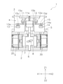
- FIG. 2 is a diagram showing a schematic diagram of the inside of an electromagnetic relay.
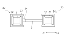
- FIG. 2 is a schematic diagram illustrating an electromagnet block.
- FIG. 2 is a schematic diagram illustrating an electromagnet block.
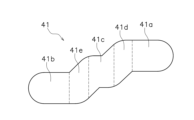
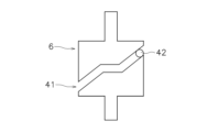
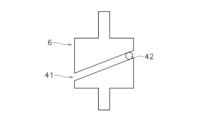
- FIG. 4 is a view of the conversion unit seen from the front-rear direction.
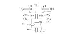
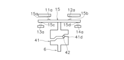
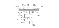
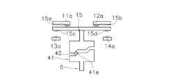
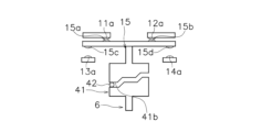
- 11A and 11B are diagrams for explaining the operation of a movable contact piece.
- 11A and 11B are diagrams for explaining the operation of a movable contact piece.
- 11A and 11B are diagrams for explaining the operation of a movable contact piece.
- 11A and 11B are diagrams for explaining the operation of a movable contact piece.
- 11A and 11B are diagrams for explaining the operation of a movable contact piece.
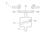
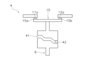
- FIGS. 13A and 13B are diagrams for explaining modified examples of the contact block.
- 13A and 13B are diagrams for explaining modified examples of the contact block and the conversion unit.
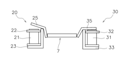
- 13A and 13B are diagrams for explaining modified examples of the electromagnet block.
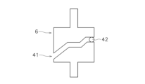
- FIG. 13 is a diagram for explaining a modified example of the conversion unit.
- FIG. 13 is a diagram for explaining a modified example of the conversion unit.
- FIG. 13 is a diagram for explaining a modified example of the conversion unit.
- the X1 direction will be described as the leftward direction
- the X2 direction will be described as the rightward direction
- the Z1 direction will be described as the upward direction
- the Z2 direction will be described as the downward direction.
- the X1 and X2 directions will be described as the left-right direction (an example of the second direction)
- the Z1 and Z2 directions perpendicular to the X1 and X2 directions will be described as the upward-downward direction (an example of the first direction)
- the direction perpendicular to the plane of the paper in FIG. 1 will be described as the front-rear direction.
- the electromagnetic relay 1 includes a base 2, a contact case 3, a contact block 4, an electromagnet block 5, a first movable member 6, a second movable member 7, and a conversion mechanism 8.
- the base 2 and contact case 3 are formed from an insulating material such as resin.
- the base 2 houses the electromagnet block 5.
- the contact case 3 houses the contact block 4.
- the contact block 4 includes a first fixed terminal 11, a second fixed terminal 12, a third fixed terminal 13, a fourth fixed terminal 14, and a movable contact piece 15.
- the first to fourth fixed terminals 11 to 14 are plate-shaped terminals and made of a conductive material.
- the first to fourth fixed terminals 11 to 14 are supported by the contact case 3.
- the first fixed terminal 11 includes a first fixed contact 11a.
- the first fixed contact 11a is disposed on the underside of the first fixed terminal 11.
- the second fixed terminal 12 is separated from the first fixed terminal 11 in the left-right direction.
- the second fixed terminal 12 includes a second fixed contact 12a.
- the second fixed contact 12a is disposed on the underside of the second fixed terminal 12.
- the third fixed terminal 13 includes a third fixed contact 13a.
- the third fixed contact 13a is disposed on the upper surface of the third fixed terminal 13.
- the third fixed contact 13a is disposed lower than the first fixed contact 11a.
- the fourth fixed terminal 14 includes a fourth fixed contact 14a.
- the fourth fixed contact 14a is disposed on the upper surface of the fourth fixed terminal 14.
- the fourth fixed contact 14a is disposed lower than the second fixed contact 12a.
- the movable contact piece 15 is a plate-shaped terminal and is made of a conductive material.
- the movable contact piece 15 extends in the left-right direction.
- the movable contact piece 15 is configured to be movable in the up-down direction.
- the movable contact piece 15 moves in the up-down direction in response to the up-down movement of the first movable member 6.
- the movable contact piece 15 is supported by the first movable member 6.
- the movable contact piece 15 is disposed below the first fixed contact 11a and the second fixed contact 12a.
- the movable contact piece 15 is disposed above the third fixed contact 13a and the fourth fixed contact 14a.
- the movable contact piece 15 includes a first movable contact 15a, a second movable contact 15b, a third movable contact 15c, and a fourth movable contact 15d.
- the first movable contact 15a and the second movable contact 15b are arranged on the upper surface of the movable contact piece 15.
- the third movable contact 15c and the fourth movable contact 15d are arranged on the lower surface of the movable contact piece 15.
- the first movable contact 15a is arranged facing the first fixed contact 11a in the vertical direction.
- the second movable contact 15b is arranged facing the second fixed contact 12a in the vertical direction.
- the third movable contact 15c is arranged facing the third fixed contact 13a in the vertical direction.
- the fourth movable contact 15d is arranged facing the fourth fixed contact 14a in the vertical direction.
- the electromagnet block 5 moves the movable contact piece 15 in the vertical direction via the first movable member 6, the second movable member 7, and the conversion mechanism 8.
- the electromagnet block 5 is disposed below the contact block 4.
- the electromagnet block 5 is supported by the base 2.
- the electromagnet block 5 includes a first coil block 20 and a second coil block 30.
- Figure 2 diagrammatically shows a state in which a voltage is applied only to the first coil block 20
- Figure 3 diagrammatically shows a state in which a voltage is applied only to the second coil block 30.
- the first coil block 20 includes a first coil 21, a first spool 22, a first yoke 23, a first movable core 24 (an example of a magnetic body), a first fixed core (not shown), and a first coil spring (not shown).
- the first coil 21 generates a magnetic force that moves the first movable core 24 in the left-right direction (leftward in this case).
- the axis of the first coil 21 extends parallel to the left-right direction.
- the first coil 21 is wound around the first spool 22.
- the first yoke 23 is arranged to surround the first coil 21.
- the first movable core 24 is configured to be movable in the left-right direction.
- the first movable core 24, the first fixed core, and the first coil spring are arranged within the first spool 22.
- the first movable core 24 is arranged opposite the first fixed core in the left-right direction.
- the first movable core 24 is arranged to the right of the first fixed core.
- the first coil spring biases the first movable core 24 to the right.
- the second coil block 30 is arranged so as to face the first coil block 20 in the left-right direction.
- the second coil block 30 is arranged to the right and away from the first coil block 20.
- the second coil block 30 includes a second coil 31, a second spool 32, a second yoke 33, a second movable iron core 34 (an example of a magnetic body), a second fixed iron core (not shown), and a second coil spring (not shown).
- the second coil 31 generates a magnetic force that moves the second movable iron core 34 in the left-right direction (to the right in this case).
- the axis of the second coil 31 extends parallel to the left-right direction.
- the second coil 31 is wound around the second spool 32.
- the second yoke 33 is arranged to surround the second coil 31.
- the second movable core 34 is configured to be movable in the left-right direction.
- the second movable core 34, the second fixed core, and the second coil spring are arranged within the second spool 32.
- the second movable core 34 is arranged opposite the second fixed core in the left-right direction.
- the second movable core 34 is arranged to the left of the second fixed core.
- the second coil spring biases the second movable core 34 to the left.
- the first movable member 6 extends in the vertical direction between the contact block 4 and the electromagnet block 5.
- the first movable member 6 is connected to the movable contact piece 15.
- the first movable member 6 is configured to be movable in the vertical direction.
- the second movable member 7 has its vertical movement guided by at least one of the base 2 and the contact case 3.
- the second movable member 7 has its horizontal movement restricted by at least one of the base 2 and the contact case 3. A portion of the first movable member 6 overlaps the second movable member 7 when viewed from the front-to-rear direction.
- the second movable member 7 is formed of an insulating material.
- the second movable member 7 is disposed between the first coil block 20 and the second coil block 30.
- the second movable member 7 is connected to the first movable iron core 24 and the second movable iron core 34.
- the second movable member 7 is configured to be movable in the left-right direction in response to the movement of the first movable iron core 24 and the second movable iron core 34.
- the second movable member 7 is configured to be capable of linear movement in the left-right direction along the axis of the first coil 21 and the axis of the second coil 31.
- the second movable member 7 is guided in its left-right movement by the base 2.
- the second movable member 7 is restricted in its up-down movement.
- the conversion mechanism 8 converts the left-right moving force of the second movable member 7 into a vertical moving force and transmits it to the first movable member 6. In other words, the conversion mechanism 8 converts the left-right linear motion of the second movable member 7 by 90 degrees and transmits it to the first movable member 6. As a result, the first movable member 6 moves up and down in response to the left-right movement of the second movable member 7.
- the conversion mechanism 8 includes a conversion part 41 and an engagement part 42.
- the conversion part 41 is disposed on one of the first movable member 6 and the second movable member 7.
- the engagement part 42 is disposed on the other of the first movable member 6 and the second movable member 7.
- the conversion part 41 is disposed on the first movable member 6, and the engagement part 42 is disposed on the second movable member 7.
- At least a portion of the conversion unit 41 extends in a direction intersecting the up-down and left-right directions. When viewed from the front-to-rear direction, at least a portion of the conversion unit 41 is inclined relative to the left-to-right direction.
- the conversion unit 41 is disposed between the first coil block 20 and the second coil block 30.
- the conversion unit 41 moves integrally with the first movable member 6.
- the conversion unit 41 has a groove shape.
- the conversion unit 41 is formed to penetrate the first movable member 6 in the front-to-rear direction.
- the conversion unit 41 may be formed in the first movable member 6 so as to be recessed in the front-to-rear direction.
- the conversion section 41 includes a first retaining section 41a, a second retaining section 41b, a neutral section 41c, a first inclined section 41d, and a second inclined section 41e.
- the first retaining section 41a, the second retaining section 41b, the neutral section 41c, the first inclined section 41d, and the second inclined section 41e are formed so as to be connected in the left-right direction.
- the first retaining section 41a, the second retaining section 41b, the neutral section 41c, the first inclined section 41d, and the second inclined section 41e are arranged in the following order from right to left: first retaining section 41a, first inclined section 41d, neutral section 41c, second inclined section 41e, second retaining section 41b.
- the first retaining portion 41a, the second retaining portion 41b, and the neutral portion 41c extend in the left-right direction.
- the first retaining portion 41a is located above the neutral portion 41c.
- the second retaining portion 41b is located below the neutral portion 41c.
- the neutral portion 41c is located in the center of the conversion portion 41 in the left-right direction.
- the dimension of the neutral portion 41c in the left-right direction is smaller than the dimension of the first retaining portion 41a and the second retaining portion 41b in the left-right direction.
- the first inclined portion 41d is located between the first retaining portion 41a and the neutral portion 41c.
- the first inclined portion 41d extends in a direction intersecting the up-down and left-right directions.
- the first inclined portion 41d extends leftward and downward from the left end of the first retaining portion 41a. It is inclined downward to the left from the first retaining portion 41a.
- the second inclined portion 41e is located between the neutral portion 41c and the second retaining portion 41b.
- the second inclined portion 41e extends in a direction intersecting the up-down and left-right directions.
- the second inclined portion 41e extends leftward and downward from the left end of the neutral portion 41c.
- the second inclined portion 41e is inclined downward to the left from the neutral portion 41c.
- the dimension of the second inclined portion 41e in the left-right direction is approximately the same as the dimension of the first inclined portion 41d in the left-right direction.
- the inclination of the second inclined portion 41e is approximately the same as the inclination of the first inclined portion 41d.
- the engaging portion 42 engages with the conversion portion 41.
- the engaging portion 42 extends in an axial manner in the front-rear direction.
- the engaging portion 42 has a cylindrical shape. At least a portion of the engaging portion 42 is disposed within the conversion portion 41.
- the engaging portion 42 moves integrally with the second movable member 7.
- the engaging portion 42 moves left-right while sliding against the inner circumferential surface of the conversion portion 41 in conjunction with left-right movement of the second movable member 7.
- the engaging portion 42 moves left-right on the first inclined portion 41d or the second inclined portion 41e, causing the first movable member 6 to move up-down.
- the engaging portion 42 may have a shape that fits along the inner circumferential surface of the conversion portion 41.
- the engagement portion 42 engages with the first holding portion 41a of the conversion portion 41.
- the third movable contact 15c is held in contact with the third fixed contact 13a
- the fourth movable contact 15d is held in contact with the fourth fixed contact 14a.
- the first movable contact 15a is separated from the first fixed contact 11a
- the second movable contact 15b is separated from the second fixed contact 12a.
- the conversion mechanism 8 converts the left-right moving force of the second movable member 7 into a vertical moving force and transmits it to the first movable member 6, thereby operating the movable contact piece 15 connected to the first movable member 6.
- the engagement portion 42 arranged on the second movable member 7 moves the first inclined portion 41d and the second inclined portion 41e in the left-right direction, thereby converting the left-right movement of the second movable member 7 into the vertical movement of the first movable member 6. This allows the conversion mechanism 8 to easily control the operation of the first to fourth movable contacts 15a to 15d.
- the third movable contact 15c and the third fixed contact 13a can be easily maintained in contact with each other, and the fourth movable contact 15d and the fourth fixed contact 14a can be easily maintained in contact with each other.
- the second retaining portion 41b By providing the second retaining portion 41b, the first movable contact 15a and the first fixed contact 11a can be easily maintained in contact with each other, and the second movable contact 15b and the second fixed contact 12a can be easily maintained in contact with each other.
- the vertical movement of the movable contact piece 15 can be stopped. This ensures time to interrupt the arc that occurs between the contacts. As a result, it is possible to reduce the contact distance, which prevents the electromagnetic relay from becoming too large in the first direction.
- the conversion unit 41 is disposed on the first movable member 6, and the engagement unit 42 is disposed on the second movable member 7.
- the conversion unit 41 may be disposed on the second movable member 7, and the engagement unit 42 may be disposed on the first movable member 6.
- the engagement unit 42 may be configured to move up and down in response to the left-right movement of the conversion unit 41.
- the configuration of the contact block 4 may be changed.
- the movable contact piece 15 has four movable contacts 15a to 15d, but the present invention may be applied to an electromagnetic relay including a movable contact piece 15 having only one movable contact.
- the contact block 4 may be configured with an a-contact as shown in FIG. 10.
- the third fixed terminal 13, the fourth fixed terminal 14, the third movable contact 15c, and the fourth movable contact 15d may be omitted.
- the contact block 4 may be configured with a b-contact as shown in FIG. 11.
- the shape of the conversion section 41 may be formed in the opposite direction to that of the above embodiment.
- the first fixed terminal 11, the second fixed terminal 12, the first movable contact 15a, and the second movable contact 15b may be omitted.
- the configuration of the electromagnet block 5 may be changed.
- the electromagnet block 5 may have a hinge-type structure, as shown in FIG. 12.
- the axis of the first coil 21 and the axis of the second coil 31 may extend parallel to the up-down direction.
- the first coil block 20 includes a first movable iron piece 25, and the second coil block 30 includes a second movable iron piece 35.
- the first movable iron piece 25 and the second movable iron piece 35 are examples of magnetic bodies.
- the second coil block 30 may be omitted.
- a return spring that biases the second movable member 7 to the right may be provided in place of the second coil block 30.
- the configuration of the conversion section 41 may be changed. As shown in FIG. 13, the second retaining section 41b may be omitted. As shown in FIG. 14, the first retaining section 41a and the second retaining section 41b may be omitted. As shown in FIG. 15, the first retaining section 41a, the second retaining section 41b, and the neutral section 41c may be omitted.
- the dimensions in the left-right direction of the first inclined section 41d and the second inclined section 41e may be different from each other.
- the inclinations of the first inclined section 41d and the second inclined section 41e may be different from each other.
- the operating speed of the movable contact piece 15 can be adjusted by the dimensions and inclinations of the first inclined section 41d and the second inclined section 41e.
- Electromagnetic relay 4: Contact block
- 5 Electromagnetic block
- 6 First movable member
- 7 Second movable member
- 8 Conversion mechanism
- 11 First fixed terminal
- 11a First fixed contact
- 15 Movable contact piece
- 15a first movable contact
- 41 conversion section
- 42 engagement section
Landscapes
- Physics & Mathematics (AREA)
- Electromagnetism (AREA)
- Electromagnets (AREA)
Abstract
電磁継電器は、接点ブロックと、電磁石ブロックと、第1可動部材と、第2可動部材と、変換機構とを備える。接点ブロックは、第1固定接点を含む第1固定端子と、第1固定接点と第1方向に対向する第1可動接点を含む可動接触片とを含む。電磁石ブロックは、磁性体と、磁性体を移動させる磁力を発生させるコイルとを含む。第1可動部材は、可動接触片に接続され第1方向に移動可能に構成される。第2可動部材は、磁性体に接続され、磁性体の移動に応じて第1方向と直交する第2方向に移動可能に構成される。変換機構は、第2可動部材の第2方向の移動力を第1方向の移動力に変換して第1可動部材に伝達する。
Description
本発明は、電磁継電器に関する。
従来、ソレノイドを駆動源とする回転機構により回転軸を回転させて接点を動作させる開閉器が知られている。
本発明の課題は、接点の動作を容易に制御することができる電磁継電器を提供することにある。
本発明の一態様に係る電磁継電器は、接点ブロックと、電磁石ブロックと、第1可動部材と、第2可動部材と、変換機構とを備える。接点ブロックは、第1固定接点を含む第1固定端子と、第1固定接点と第1方向に対向する第1可動接点を含む可動接触片とを含む。電磁石ブロックは、磁性体と、磁性体を移動させる磁力を発生させるコイルとを含む。第1可動部材は、可動接触片に接続され第1方向に移動可能に構成される。第2可動部材は、磁性体に接続され、磁性体の移動に応じて第1方向と直交する第2方向に移動可能に構成される。変換機構は、第2可動部材の第2方向の移動力を第1方向の移動力に変換して第1可動部材に伝達する。
この電磁継電器では、第2可動部材の第2方向の移動力が第1方向の移動力に変換されて第1可動部材に伝達されることで、第1可動部材に接続された可動接触片が動作する。これにより、接点の動作を容易に制御することができる。
変換機構は、少なくとも一部が第1方向及び第2方向と交差する方向に延びる変換部と、前記変換部に係合する係合部とを含んでもよい。第1可動部材及び第2可動部材の一方は、変換部を含んでもよい。第1可動部材及び第2可動部材の他方は、係合部を含んでもよい。この場合は、簡単な構成で接点の動作を容易に制御することができる。また、例えば、変換部の傾きを調整することで、接点の動作を容易に制御することができる。
変換部は、第2方向に対して平行に延びる中立部を含んでもよい。中立部は、第2方向における変換部の中央に配置されてもよい。この場合は、中立部において、可動接触片の第1方向の移動を停止させることができる。
変換部は、第2方向に対して平行に延びる保持部と、中立部と保持部の間に配置され第1方向及び第2方向と交差する方向に延びる傾斜部とを含んでもよい。この場合は、例えば、係合部が保持部に係合しているときに、第1可動接点が第1固定接点に接触するように保持部を設定することで、第1可動接点が第1固定接点に接触した状態を保持部によって保持できる。
変換部は、第2方向に対して平行に延びる保持部と、保持部から第1方向及び第2方向と交差する方向に延びる傾斜部とを含んでもよい。この場合は、例えば、係合部が保持部に係合しているときに、第1可動接点が第1固定接点に接触するように保持部を設定することで、第1可動接点が第1固定接点に接触した状態を保持部によって保持できる。
接点ブロックは、第2固定接点を含む第2固定端子をさらに含んでもよい。第2固定接点は、第1固定接点に対して第1方向に離れて配置されてもよい。可動接触片は、第2固定接点と第1方向に対向する第2可動接点をさらに含んでもよい。第1可動接点は、係合部が中立部に位置している時に第1固定接点から開離した状態にあってもよい。第2可動接点は、係合部が中立部に位置している時に第2固定接点から開離した状態にあってもよい。この場合は、中立部によって可動接触片の第1方向の移動を停止させることができるので、接点間に生じるアークを遮断する時間を確保できる。その結果、接点距離を小さくすることが可能になるので、第1方向において電磁継電器の大型化を抑制できる。
接点ブロックは、第2固定接点を含む第2固定端子をさらに含んでもよい。第2固定接点は、前記第1固定接点に対して前記第1方向に離れて配置されてもよい。可動接触片は、第2固定接点と第1方向に対向する第2可動接点をさらに含んでもよい。第1可動接点は、係合部が保持部に位置している時に第1固定接点に接触した状態が保持されてもよい。第2可動接点は、係合部が保持部に位置している時に第2固定接点から離れてもよい。この場合は、第1可動接点が第1固定接点に接触した状態を保持部によって保持できる。
本発明によれば、接点の動作を容易に制御することができる電磁継電器を提供することができる。
以下、本発明の一態様に係る電磁継電器1の実施形態について、図面を参照して説明する。なお、図面を参照するときにおいて、X1方向を左方向、X2方向を右方向、Z1方向を上方向、Z2方向を下方向として説明する。また、X1,X2方向を左右方向(第2方向の一例)、X1,X2方向と直交するZ1,Z2方向を上下方向(第1方向の一例)、図1の紙面と直交する方向を前後方向として説明する。これらの方向は、説明の便宜上、定義されるものであって、電磁継電器1の配置方向を限定するものではない。
図1に示すように、電磁継電器1は、ベース2と、接点ケース3と、接点ブロック4と、電磁石ブロック5と、第1可動部材6と、第2可動部材7と、変換機構8とを備えている。
ベース2及び接点ケース3は、樹脂などの絶縁材で形成されている。ベース2は、電磁石ブロック5を収容する。接点ケース3は、接点ブロック4を収容する。
接点ブロック4は、第1固定端子11と、第2固定端子12と、第3固定端子13と、第4固定端子14と、可動接触片15とを含む。第1~第4固定端子11~14は、板状の端子であり、導電性を有する材料で形成されている。第1~第4固定端子11~14は、接点ケース3に支持されている。
第1固定端子11は、第1固定接点11aを含む。第1固定接点11aは、第1固定端子11の下面に配置されている。第2固定端子12は、第1固定端子11と左右方向に離れている。第2固定端子12は、第2固定接点12aを含む。第2固定接点12aは、第2固定端子12の下面に配置されている。
第3固定端子13は、第3固定端子13は、第3固定接点13aを含む。第3固定接点13aは、第3固定端子13の上面に配置されている。第3固定接点13aは、第1固定接点11aよりも下方に配置されている。第4固定端子14は、第4固定接点14aを含む。第4固定接点14aは、第4固定端子14の上面に配置されている。第4固定接点14aは、第2固定接点12aよりも下方に配置されている。
可動接触片15は、板状の端子であり、導電性を有する材料で形成されている。可動接触片15は、左右方向に延びている。可動接触片15は、上下方向に移動可能に構成されている。可動接触片15は、第1可動部材6の上下方向の移動に応じて上下方向に移動する。可動接触片15は、第1可動部材6に支持されている。可動接触片15は、第1固定接点11a及び第2固定接点12aの下方に配置されている。可動接触片15は、第3固定接点13a及び第4固定接点14aの上方に配置されている。
可動接触片15は、第1可動接点15aと、第2可動接点15bと、第3可動接点15cと、第4可動接点15dとを含む。第1可動接点15a及び第2可動接点15bは、可動接触片15の上面に配置されている。第3可動接点15c及び第4可動接点15dは、可動接触片15の下面に配置されている。第1可動接点15aは、第1固定接点11aと上下方向に対向して配置されている。第2可動接点15bは、第2固定接点12aと上下方向に対向して配置されている。第3可動接点15cは、第3固定接点13aと上下方向に対向して配置されている。第4可動接点15dは、第4固定接点14aと上下方向に対向して配置されている。
電磁石ブロック5は、第1可動部材6、第2可動部材7及び変換機構8を介して、可動接触片15を上下方向に移動させる。電磁石ブロック5は、接点ブロック4の下方に配置されている。電磁石ブロック5は、ベース2に支持されている。
図2及び図3に模式的に示すように、電磁石ブロック5は、第1コイルブロック20と、第2コイルブロック30とを含む。図2では、第1コイルブロック20のみに電圧が印加された状態を模式的に示し、図3は、第2コイルブロック30のみに電圧が印加された状態を模式的に示している。
第1コイルブロック20は、第1コイル21と、第1スプール22と、第1ヨーク23と、第1可動鉄心24(磁性体の一例)と、第1固定鉄心(図示せず)と、第1コイルばね(図示せず)とを含む。第1コイル21は、第1可動鉄心24を左右方向(ここでは左方)に移動させる磁力を発生させる。第1コイル21の軸線は、左右方向に対して平行に延びている。第1コイル21は、第1スプール22に巻回されている。第1ヨーク23は、第1コイル21を囲むように配置されている。
第1可動鉄心24は、左右方向に移動可能に構成される。第1可動鉄心24、第1固定鉄心及び第1コイルばねは、第1スプール22内に配置されている。第1可動鉄心24は、第1固定鉄心と左右方向に対向して配置されている。第1可動鉄心24は、第1固定鉄心の右方に配置されている。第1コイルばねは、第1可動鉄心24を右方に付勢する。
第2コイルブロック30は、第1コイルブロック20と左右方向に対向するように配置されている。第2コイルブロック30は、第1コイルブロック20から右方に離れて配置されている。
第2コイルブロック30は、第2コイル31と、第2スプール32と、第2ヨーク33と、第2可動鉄心34(磁性体の一例)と、第2固定鉄心(図示せず)と、第2コイルばね(図示せず)とを含む。第2コイル31は、第2可動鉄心34を左右方向(ここでは右方)に移動させる磁力を発生させる。第2コイル31の軸線は、左右方向に対して平行に延びている。第2コイル31は、第2スプール32に巻回されている。第2ヨーク33は、第2コイル31を囲むように配置されている。
第2可動鉄心34は、左右方向に移動可能に構成される。第2可動鉄心34、第2固定鉄心及び第2コイルばねは、第2スプール32内に配置されている。第2可動鉄心34は、第2固定鉄心と左右方向に対向して配置されている。第2可動鉄心34は、第2固定鉄心の左方に配置されている。第2コイルばねは、第2可動鉄心34を左方に付勢する。
第1可動部材6は、接点ブロック4と電磁石ブロック5とに亘って上下方向に延びている。第1可動部材6は、可動接触片15に接続されている。第1可動部材6は、上下方向に移動可能に構成される。第2可動部材7は、ベース2及び接点ケース3の少なくとも一方によって上下方向の移動がガイドされている。第2可動部材7は、ベース2及び接点ケース3の少なくとも一方によって左右方向の移動が規制されている。第1可動部材6の一部は、前後方向から見て、第2可動部材7重なる。
第2可動部材7は、絶縁材で形成されている。第2可動部材7は、第1コイルブロック20と第2コイルブロック30の間に配置されている。第2可動部材7は、第1可動鉄心24と第2可動鉄心34とに接続されている。第2可動部材7は、第1可動鉄心24及び第2可動鉄心34の移動に応じて左右方向に移動可能に構成されている。第2可動部材7は、第1コイル21の軸線及び第2コイル31の軸線に沿って左右方向に直線運動可能に構成されている。第2可動部材7は、ベース2によって左右方向の移動がガイドされている。第2可動部材7は、上下方向の移動が規制されている。
変換機構8は、第2可動部材7の左右方向の移動力を上下方向の移動力に変換して第1可動部材6に伝達する。すなわち、変換機構8は、第2可動部材7の左右方向の直線運動を90度変換して第1可動部材6に伝達する。これにより、第1可動部材6は、第2可動部材7の左右方向の移動に応じて、上下方向に移動する。
変換機構8は、変換部41と、係合部42とを含む。変換部41は、第1可動部材6及び第2可動部材7の一方に配置される。係合部42は、第1可動部材6及び第2可動部材7の他方に配置される。本実施形態では、変換部41は、第1可動部材6に配置され、係合部42は、第2可動部材7に配置されている。
変換部41は、少なくとも一部が上下方向及び左右方向と交差する方向に延びている。変換部41は、前後方向から見て、少なくとも一部が左右方向に対して傾斜している。変換部41は、第1コイルブロック20と第2コイルブロック30の間に配置されている。変換部41は、第1可動部材6と一体的に移動する。変換部41は、溝形状を有している。変換部41は、第1可動部材6を前後方向に貫通して形成されている。変換部41は、第1可動部材6において、前後方向に凹むように形成されてもよい。
変換部41は、第1保持部41aと、第2保持部41bと、中立部41cと、第1傾斜部41dと、第2傾斜部41eとを含む。第1保持部41a、第2保持部41b、中立部41c、第1傾斜部41d及び第2傾斜部41eは、左右方向に連なるように形成されている。第1保持部41a、第2保持部41b、中立部41c、第1傾斜部41d及び第2傾斜部41eは、右から左に向かって第1保持部41a、第1傾斜部41d、中立部41c、第2傾斜部41e、第2保持部41bの順に並んでいる。
第1保持部41a、第2保持部41b及び中立部41cは、左右方向に延びている。第1保持部41aは、中立部41cよりも上方に位置する。第2保持部41bは、中立部41cよりも下方に位置する。中立部41cは、左右方向における変換部41の中央に位置する。左右方向における中立部41cの寸法は、左右方向における第1保持部41a及び第2保持部41bの寸法よりも小さい。
第1傾斜部41dは、第1保持部41aと中立部41cの間に位置する。第1傾斜部41dは、上下方向及び左右方向と交差する方向に延びている。第1傾斜部41dは、第1保持部41aの左端から左方かつ下方に延びている。第1保持部41aから左下がりに傾斜している。
第2傾斜部41eは、中立部41cと第2保持部41bの間に位置する。第2傾斜部41eは、上下方向及び左右方向と交差する方向に延びている。第2傾斜部41eは、中立部41cの左端から左方かつ下方に延びている。第2傾斜部41eは、中立部41cから左下がりに傾斜している。左右方向における第2傾斜部41eの寸法は、左右方向における第1傾斜部41dの寸法と同程度である。第2傾斜部41eの傾きは、第1傾斜部41dの傾きと同程度である。
係合部42は、変換部41と係合する。係合部42は、軸状に前後方向に延びている。本実施形態では、係合部42は、円柱形状を有している。係合部42は、少なくとも一部が変換部41内に配置されている。係合部42は、第2可動部材7と一体的に移動する。係合部42は、第2可動部材7の左右方向の移動に伴い変換部41の内周面に対して摺動しながら左右方向に移動する。係合部42が第1傾斜部41d又は第2傾斜部41eを左右方向に移動することで、第1可動部材6は上下方向に移動する。係合部42は、変換部41の内周面に沿う形状を有してもよい。
次に、図5から9を参照して、係合部42の移動に伴う可動接触片15の動作について説明する。具体的には、第2コイルブロック30への電圧の印加が停止されて、第1コイルブロック20に電圧が印加されたときの可動接触片15の動作について説明する。
図5に示すように、第2コイルブロック30のみに電圧が印加されている状態では、係合部42は、変換部41の第1保持部41aに係合する。係合部42が第1保持部41aと係合した状態では、第3可動接点15cが第3固定接点13aに接触した状態が保持され、第4可動接点15dが第4固定接点14aに接触した状態が保持される。このとき、第1可動接点15aは、第1固定接点11aから開離しており、第2可動接点15bは、第2固定接点12aから開離している。
図6に示すように、第2コイルブロック30の電圧の印加が停止され、第1コイルブロック20の電圧が印加されると、第1可動鉄心24及び第2可動鉄心34が左方に移動することで、係合部42は、第2可動部材7とともに左方に移動して第1傾斜部41dと係合する。係合部42が第1傾斜部41dと係合することで、第1可動部材6が係合部42に押し上げられて、可動接触片15が上方に移動する。これにより、第3可動接点15cは、第3固定接点13aから開離し、第4可動接点15dは、第4固定接点14aから開離する。
図7に示すように、係合部42が中立部41cと係合した状態では、上下方向において第1可動部材6の位置が維持されるので、可動接触片15の上下方向の移動が抑制される。すなわち、係合部42が中立部41cと係合した状態では、可動接触片15は上下方向に移動しない。このため、第1~第4可動接点15a~15dの移動が抑制される。このとき、各接点は互いに開離した状態にあり、各接点間の距離は変化しない。
図8に示すように、係合部42が第2傾斜部41eと係合することで、第1可動部材6が係合部42に押し上げられて、可動接触片15がさらに上方に移動する。これにより、第1可動接点15aは、第1固定接点11aと接触し、第2可動接点15bは、第2固定接点12aと接触する。
図9に示すように、係合部42が第2傾斜部41eと係合した状態では、第1可動接点15aが第1固定接点11aに接触した状態が保持され、第2可動接点15bが第2固定接点12aに接触した状態が保持される。なお、第1コイルブロック20への電圧の印加が停止されて、第2コイルブロック30に電圧が印加されたときは、係合部42が第2傾斜部41e及び第1傾斜部41dを左右方向に移動することで、可動接触片15が下方に移動する。
上記構成の電磁継電器1では、変換機構8によって第2可動部材7の左右方向の移動力が上下方向の移動力に変換されて第1可動部材6に伝達されることで、第1可動部材6に接続された可動接触片15が動作する。詳細には、第2可動部材7に配置された係合部42が第1傾斜部41d及び第2傾斜部41eを左右方向に移動することで、第2可動部材7の左右方向の移動が第1可動部材6の上下方向の移動に変換される。これにより、変換機構8によって第1~第4可動接点15a~15dの動作を容易に制御することができる。
第1保持部41aを設けることで、第3可動接点15cと第3固定接点13aとが接触した状態、並びに第4可動接点15dと第4固定接点14aとが接触した状態を容易に維持できる。同様に第2保持部41bを設けることで、第1可動接点15aと第1固定接点11aとが接触した状態、並びに第2可動接点15bと第2固定接点12aとが接触した状態を容易に維持できる
中立部41cを設けることで、可動接触片15の上下方向の移動を停止させることができる。これにより、接点間に生じるアークを遮断する時間を確保することができる。その結果、接点距離を小さくすることが可能になるので、第1方向において電磁継電器の大型化を抑制できる。
以上、本発明の一態様に係る電磁継電器の実施形態について説明したが、本発明は上記実施形態に限定されるものではなく、発明の要旨を逸脱しない範囲で種々の変更が可能である。
前記実施形態では、変換部41は、第1可動部材6に配置され、係合部42は、第2可動部材7に配置されていた。しかしながら、変換部41は、第2可動部材7に配置され、係合部42は、第1可動部材6に配置されてもよい。すなわち、変換部41の左右方向に移動に応じて係合部42が上下方向に移動するような構成であってもよい。
接点ブロック4の構成は変更されてもよい。前記実施形態では、可動接触片15は、4つの可動接点15a~15dを有していたが、1つの可動接点のみを有する可動接触片15を備える電磁継電器に本発明を適用してもよい。接点ブロック4は、図10に示すように、a接点で構成されてもよい。例えば、前記実施形態において、第3固定端子13、第4固定端子14、第3可動接点15c及び第4可動接点15dは、省略されてもよい。接点ブロック4は、図11に示すように、b接点で構成されてもよい。この場合、変換部41の形状を前記実施形態と逆に形成してもよい。前記実施形態において、第1固定端子11、第2固定端子12、第1可動接点15a及び第2可動接点15bは、省略されてもよい。
電磁石ブロック5の構成は、変更されてもよい。電磁石ブロック5は、図12に模式的に示すように、ヒンジ型の構造を有してもよい。この場合、第1コイル21の軸線及び第2コイル31の軸線は、上下方向に対して平行に延びていてもよい。図12に示す実施例において、第1コイルブロック20は、第1可動鉄片25を含み、第2コイルブロック30は、第2可動鉄片35を含む。第1可動鉄片25及び第2可動鉄片35は、磁性体の一例である。また、第2コイルブロック30は、省略されてもよい。この場合、第2コイルブロック30に換えて、第2可動部材7を右方に付勢する復帰ばねを設けてもよい。
変換部41の構成は変更されてもよい。図13に示すように、第2保持部41bは省略されてもよい。図14に示すように、第1保持部41a及び第2保持部41bは省略されてもよい。図15に示すように、第1保持部41a、第2保持部41b及び中立部41cは、省略されてもよい。第1傾斜部41dと第2傾斜部41eの左右方向における寸法が互いに異なってもよい。第1傾斜部41dと第2傾斜部41eの傾きが互いに異なっていてもよい。第1傾斜部41d及び第2傾斜部41eの寸法や傾きによって可動接触片15の動作速度を調整できる。
1:電磁継電器、4:接点ブロック、5:電磁石ブロック、6:第1可動部材、7:第2可動部材、8:変換機構、11:第1固定端子、11a:第1固定接点、15:可動接触片、15a:第1可動接点、41:変換部、42:係合部
Claims (7)
- 第1固定接点を含む第1固定端子と、前記第1固定接点と第1方向に対向する第1可動接点を含む可動接触片とを含む接点ブロックと、
磁性体と、前記磁性体を移動させる磁力を発生させるコイルとを含む電磁石ブロックと、
前記可動接触片に接続され前記第1方向に移動可能に構成される第1可動部材と
前記磁性体に接続され、前記磁性体の移動に応じて前記第1方向と直交する第2方向に移動可能に構成される第2可動部材と、
前記第2可動部材の前記第2方向の移動力を前記第1方向の移動力に変換して前記第1可動部材に伝達する変換機構と、
を備える、
電磁継電器。 - 前記変換機構は、少なくとも一部が前記第1方向及び前記第2方向と交差する方向に延びる変換部と、前記変換部に係合する係合部とを含み、
前記第1可動部材及び前記第2可動部材の一方は、前記変換部を含み、
前記第1可動部材及び前記第2可動部材の他方は、前記係合部を含む、
請求項1に記載の電磁継電器。 - 前記変換部は、前記第2方向に対して平行に延びる中立部を含み、
前記中立部は、前記第2方向における前記変換部の中央に配置される、
請求項2に記載の電磁継電器。 - 前記変換部は、前記第2方向に対して平行に延びる保持部と、前記中立部と前記保持部の間に配置され前記第1方向及び前記第2方向と交差する方向に延びる傾斜部とを含む、
請求項3に記載の電磁継電器。 - 前記変換部は、前記第2方向に対して平行に延びる保持部と、前記保持部から前記第1方向及び前記第2方向と交差する方向に延びる傾斜部とを含む、
請求項2に記載の電磁継電器。 - 前記接点ブロックは、第2固定接点を含む第2固定端子をさらに含み、
前記第2固定接点は、前記第1固定接点に対して前記第1方向に離れて配置され、
前記可動接触片は、前記第2固定接点と前記第1方向に対向する第2可動接点をさらに含み、
前記第1可動接点は、前記係合部が前記中立部に位置している時に前記第1固定接点から開離した状態にあり、
前記第2可動接点は、前記係合部が前記中立部に位置している時に前記第2固定接点から開離した状態にある、
請求項3又は4にいずれかに記載の電磁継電器。 - 前記接点ブロックは、第2固定接点を含む第2固定端子をさらに含み、
前記第2固定接点は、前記第1固定接点に対して前記第1方向に離れて配置され、
前記可動接触片は、前記第2固定接点と前記第1方向に対向する第2可動接点をさらに含み、
前記第1可動接点は、前記係合部が前記保持部に位置している時に前記第1固定接点に接触した状態が保持され、
前記第2可動接点は、前記係合部が前記保持部に位置している時に前記第2固定接点から離れている、
請求項5に記載の電磁継電器。
Applications Claiming Priority (2)
| Application Number | Priority Date | Filing Date | Title |
|---|---|---|---|
| JP2023035730A JP2024126946A (ja) | 2023-03-08 | 2023-03-08 | 電磁継電器 |
| JP2023-035730 | 2023-03-08 |
Publications (1)
| Publication Number | Publication Date |
|---|---|
| WO2024185487A1 true WO2024185487A1 (ja) | 2024-09-12 |
Family
ID=92674618
Family Applications (1)
| Application Number | Title | Priority Date | Filing Date |
|---|---|---|---|
| PCT/JP2024/006031 Ceased WO2024185487A1 (ja) | 2023-03-08 | 2024-02-20 | 電磁継電器 |
Country Status (2)
| Country | Link |
|---|---|
| JP (1) | JP2024126946A (ja) |
| WO (1) | WO2024185487A1 (ja) |
Citations (5)
| Publication number | Priority date | Publication date | Assignee | Title |
|---|---|---|---|---|
| KR20120100560A (ko) * | 2011-03-04 | 2012-09-12 | (주)파워풀 | 절전형 전자개폐기 |
| WO2012124164A1 (ja) * | 2011-03-14 | 2012-09-20 | オムロン株式会社 | 電磁継電器 |
| CN102915879A (zh) * | 2012-10-23 | 2013-02-06 | 郏威栋 | 推拉式磁保持继电器 |
| JP2018107044A (ja) * | 2016-12-27 | 2018-07-05 | パナソニックIpマネジメント株式会社 | 接点装置 |
| CN111785571A (zh) * | 2020-08-05 | 2020-10-16 | 西安宏发电器有限公司 | 一种电磁继电器结构 |
-
2023
- 2023-03-08 JP JP2023035730A patent/JP2024126946A/ja active Pending
-
2024
- 2024-02-20 WO PCT/JP2024/006031 patent/WO2024185487A1/ja not_active Ceased
Patent Citations (5)
| Publication number | Priority date | Publication date | Assignee | Title |
|---|---|---|---|---|
| KR20120100560A (ko) * | 2011-03-04 | 2012-09-12 | (주)파워풀 | 절전형 전자개폐기 |
| WO2012124164A1 (ja) * | 2011-03-14 | 2012-09-20 | オムロン株式会社 | 電磁継電器 |
| CN102915879A (zh) * | 2012-10-23 | 2013-02-06 | 郏威栋 | 推拉式磁保持继电器 |
| JP2018107044A (ja) * | 2016-12-27 | 2018-07-05 | パナソニックIpマネジメント株式会社 | 接点装置 |
| CN111785571A (zh) * | 2020-08-05 | 2020-10-16 | 西安宏发电器有限公司 | 一种电磁继电器结构 |
Also Published As
| Publication number | Publication date |
|---|---|
| JP2024126946A (ja) | 2024-09-20 |
Similar Documents
| Publication | Publication Date | Title |
|---|---|---|
| US9679707B2 (en) | Contact device and electromagnetic relay | |
| US8659375B2 (en) | Reed switch | |
| KR102086878B1 (ko) | 전자 접촉기 | |
| JP4466421B2 (ja) | 封止接点装置 | |
| KR20130116865A (ko) | 전자 개폐기 | |
| WO2016092955A1 (ja) | 遮断器及び操作器並びに開閉装置 | |
| TW202032597A (zh) | 繼電器 | |
| JP2025021011A (ja) | 電磁継電器 | |
| JP2020115407A (ja) | 電磁リレー | |
| JP2024126946A (ja) | 電磁継電器 | |
| JP2020074333A (ja) | 電磁継電器 | |
| WO2016129144A1 (ja) | リレー | |
| JP6685024B2 (ja) | 電磁継電器 | |
| WO2019187780A1 (ja) | リレー | |
| US10790106B2 (en) | Relay device | |
| JP6726869B2 (ja) | 接点装置および電磁継電器 | |
| WO2020090265A1 (ja) | リレー | |
| KR20170044475A (ko) | 배터리 릴레이 | |
| CN112582217B (zh) | 继电器 | |
| KR20160003787U (ko) | 전자접촉기 액추에이터 | |
| JP7380028B2 (ja) | リレー | |
| WO2022181117A1 (ja) | 電磁継電器 | |
| JP4829097B2 (ja) | 電磁アクチュエータ | |
| WO2018030100A1 (ja) | 電磁継電器 | |
| JPS6346999Y2 (ja) |
Legal Events
| Date | Code | Title | Description |
|---|---|---|---|
| 121 | Ep: the epo has been informed by wipo that ep was designated in this application |
Ref document number: 24766858 Country of ref document: EP Kind code of ref document: A1 |
|
| NENP | Non-entry into the national phase |
Ref country code: DE |
|
| 122 | Ep: pct application non-entry in european phase |
Ref document number: 24766858 Country of ref document: EP Kind code of ref document: A1 |