WO2024185396A1 - 減衰バルブおよび緩衝器 - Google Patents
減衰バルブおよび緩衝器 Download PDFInfo
- Publication number
- WO2024185396A1 WO2024185396A1 PCT/JP2024/004470 JP2024004470W WO2024185396A1 WO 2024185396 A1 WO2024185396 A1 WO 2024185396A1 JP 2024004470 W JP2024004470 W JP 2024004470W WO 2024185396 A1 WO2024185396 A1 WO 2024185396A1
- Authority
- WO
- WIPO (PCT)
- Prior art keywords
- valve
- annular
- seat
- leaf
- valve body
- Prior art date
- Legal status (The legal status is an assumption and is not a legal conclusion. Google has not performed a legal analysis and makes no representation as to the accuracy of the status listed.)
- Ceased
Links
Images


Classifications
-
- F—MECHANICAL ENGINEERING; LIGHTING; HEATING; WEAPONS; BLASTING
- F16—ENGINEERING ELEMENTS AND UNITS; GENERAL MEASURES FOR PRODUCING AND MAINTAINING EFFECTIVE FUNCTIONING OF MACHINES OR INSTALLATIONS; THERMAL INSULATION IN GENERAL
- F16F—SPRINGS; SHOCK-ABSORBERS; MEANS FOR DAMPING VIBRATION
- F16F9/00—Springs, vibration-dampers, shock-absorbers, or similarly-constructed movement-dampers using a fluid or the equivalent as damping medium
- F16F9/32—Details
- F16F9/50—Special means providing automatic damping adjustment, i.e. self-adjustment of damping by particular sliding movements of a valve element, other than flexions or displacement of valve discs; Special means providing self-adjustment of spring characteristics
- F16F9/512—Means responsive to load action, i.e. static load on the damper or dynamic fluid pressure changes in the damper, e.g. due to changes in velocity
-
- F—MECHANICAL ENGINEERING; LIGHTING; HEATING; WEAPONS; BLASTING
- F16—ENGINEERING ELEMENTS AND UNITS; GENERAL MEASURES FOR PRODUCING AND MAINTAINING EFFECTIVE FUNCTIONING OF MACHINES OR INSTALLATIONS; THERMAL INSULATION IN GENERAL
- F16F—SPRINGS; SHOCK-ABSORBERS; MEANS FOR DAMPING VIBRATION
- F16F9/00—Springs, vibration-dampers, shock-absorbers, or similarly-constructed movement-dampers using a fluid or the equivalent as damping medium
- F16F9/32—Details
- F16F9/34—Special valve constructions; Shape or construction of throttling passages
- F16F9/348—Throttling passages in the form of annular discs or other plate-like elements which may or may not have a spring action, operating in opposite directions or singly, e.g. annular discs positioned on top of the valve or piston body
- F16F9/3485—Throttling passages in the form of annular discs or other plate-like elements which may or may not have a spring action, operating in opposite directions or singly, e.g. annular discs positioned on top of the valve or piston body characterised by features of supporting elements intended to guide or limit the movement of the annular discs
-
- F—MECHANICAL ENGINEERING; LIGHTING; HEATING; WEAPONS; BLASTING
- F16—ENGINEERING ELEMENTS AND UNITS; GENERAL MEASURES FOR PRODUCING AND MAINTAINING EFFECTIVE FUNCTIONING OF MACHINES OR INSTALLATIONS; THERMAL INSULATION IN GENERAL
- F16F—SPRINGS; SHOCK-ABSORBERS; MEANS FOR DAMPING VIBRATION
- F16F9/00—Springs, vibration-dampers, shock-absorbers, or similarly-constructed movement-dampers using a fluid or the equivalent as damping medium
- F16F9/32—Details
- F16F9/44—Means on or in the damper for manual or non-automatic adjustment; such means combined with temperature correction
- F16F9/46—Means on or in the damper for manual or non-automatic adjustment; such means combined with temperature correction allowing control from a distance, i.e. location of means for control input being remote from site of valves, e.g. on damper external wall
- F16F9/466—Throttling control, i.e. regulation of flow passage geometry
- F16F9/467—Throttling control, i.e. regulation of flow passage geometry using rotary valves
Definitions
- the present invention relates to a damping valve and a shock absorber.
- Shock absorbers are used, for example, by being interposed between the body and wheels of a vehicle in order to improve the ride comfort of the vehicle, suppressing vibrations of the body and wheels with the damping force they exert when expanding and contracting.
- Such a shock absorber includes, for example, a cylinder, a rod that is movably inserted into the cylinder, a piston that is slidably inserted into the cylinder and divides the inside of the cylinder into an expansion side chamber and a compression side chamber, a free piston that is slidably inserted into the cylinder and divides an air chamber below the compression side chamber in the cylinder, a damping passage provided in the piston that connects the expansion side chamber and the compression side chamber, and a damping valve provided in the damping passage.
- vehicle shock absorbers are required to exhibit damping force characteristics that increase the damping coefficient in the very low speed range where the extension/retraction speed is lower than the low speed range, and quickly increase the damping force when the extension/retraction stroke switches, and make the damping coefficient smaller in the low speed range than in the very low speed range, and furthermore, in the medium to high speed range above low speed, the damping coefficient is proportional to the extension/retraction speed but smaller than in the low speed range.
- the damping valve is equipped with an annular leaf valve that is fixed on the inner circumference and allows deflection on the outer circumference, and an annular opposing seat that faces the outer circumference of the leaf valve but does not contact it, and a valve seat member that has a port on the inner circumference of the opposing seat, and provides resistance to the flow of hydraulic oil between the expansion side chamber and the compression side chamber.
- Conventional damping valves equipped with a leaf valve and an opposing seat, can provide good damping force characteristics when the shock absorber expands and contracts at very low speeds, but because the leaf valve bends and opens when the shock absorber is expanded and contracted, it is not possible to obtain different damping force characteristics when the shock absorber is expanded and contracted.
- the present invention aims to provide a damping valve that can function as a check valve while suppressing fatigue of the leaf valve, and a shock absorber that is equipped with a damping valve and can improve the ride comfort of the vehicle.
- the damping valve of the present invention comprises an annular valve body in which one of the inner circumference or the outer circumference is a fixed end and the other of the inner circumference or the outer circumference is a free end that is allowed to bend relative to the fixed end, an annular opposing seat portion that faces at least a part of the circumferential surface of the free end side of the valve body, a port that is provided radially closer to the fixed end side of the valve body than the opposing seat portion, and a valve seat member that is provided between the opposing seat portion and the port and faces the valve body in the axial direction, allowing the valve body to be seated and separated from it, and the valve body comprises an annular leaf valve and a backup valve that is annular and overlaps the valve seat member side of the leaf valve to suppress bending of the free end of the leaf valve towards the valve seat member side.
- valve disc With a damping valve configured in this manner, when the valve disc receives pressure from the port side, it bends to open the port and provide resistance to the flow of liquid passing through the port, and when it receives pressure pressing the valve disc toward the valve seat member, it seats on the annular valve seat and closes the port, so that it functions as a damping valve for the flow of liquid attempting to pass through the port to one side and as a check valve for the flow of liquid attempting to pass through the port to the other side.
- the backup valve abuts against the valve seat member side of the leaf valve to support the leaf valve and suppress bending of the middle part of the leaf valve, so that the stress acting on the leaf valve is reduced and fatigue of the leaf valve can be suppressed.
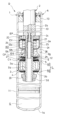
- FIG. 1 is a vertical sectional view of a shock absorber to which a damping valve according to an embodiment of the present invention is applied.
- FIG. 2 is a partially enlarged cross-sectional view of a shock absorber to which a damping valve according to an embodiment of the present invention is applied.
- FIG. 3 is a diagram showing the damping force characteristics of a shock absorber to which the damping valve according to one embodiment of the present invention is applied.
- FIG. 4 is a partially enlarged cross-sectional view of a damping valve in a first modified example of an embodiment of the present invention.
- FIG. 5 is a partially enlarged cross-sectional view of a damping valve in a second modified example of an embodiment of the present invention.
- a shock absorber D in one embodiment comprises a shock absorber body A that is expandable and contractible and has a cylinder 1 as an outer tube and a rod 2 movably inserted into the cylinder 1, and an expansion side sub-valve EV and a compression side sub-valve CV as damping valves provided between an expansion side chamber R1 and a compression side chamber R2 as two working chambers provided in the shock absorber body A.
- This shock absorber D is used by being interposed between the body and wheels of a vehicle (not shown) to suppress vibrations of the body and wheels.
- the shock absorber body A includes a cylindrical cylinder 1 with a bottom as an outer tube, a rod 2 that is movably inserted into the cylinder 1, and a piston 3 that is connected to the rod 2 and movably inserted into the cylinder 1, and that divides the inside of the cylinder 1 into an extension side chamber R1 and a compression side chamber R2 as working chambers.
- a bracket (not shown) is provided at the base end of rod 2, which is the upper end in FIG. 1, and rod 2 is connected to one of the vehicle body and the wheel via said bracket (not shown).
- a bracket (not shown) is also provided at bottom 1a of cylinder 1, and cylinder 1 is connected to the other of the vehicle body and the wheel via said bracket (not shown).
- shock absorber D is interposed between the vehicle body and the wheels.
- rod 2 moves in and out of cylinder 1
- shock absorber D expands and contracts
- piston 3 moves up and down (axially) within cylinder 1.
- the shock absorber body A also has an annular rod guide 10 that closes the upper end of the cylinder 1 and through which the rod 2 is inserted so as to be able to slide freely around its inner circumference. This makes the inside of the cylinder 1 an enclosed space. A free piston 11 is inserted so as to be able to slide freely on the opposite side of the piston 3 from the rod 2 inside the cylinder 1.
- a liquid chamber L is formed above the free piston 11 in the cylinder 1, and an air chamber G is formed below it. Furthermore, the liquid chamber L is divided by the piston 3 into an extension side chamber R1 on the rod 2 side and a compression side chamber R2 on the piston 3 side, and the extension side chamber R1 and the compression side chamber R2 are each filled with liquid.
- the liquid filled in the shock absorber body A may be hydraulic oil, water, an aqueous solution, or other liquid.
- the air chamber G is filled with air or a gas such as nitrogen gas in a compressed state.
- a bladder or bellows may be used to separate the liquid chamber L and the air chamber G, and the configuration of the movable partition that separates the liquid chamber L and the air chamber G may be changed as appropriate.
- the shock absorber D is a single-rod, single-cylinder shock absorber, and when the shock absorber D expands or contracts, the free piston 11 expands or contracts the air chamber G to compensate for the volume of the rod 2 moving in and out of the cylinder 1.
- the configuration for this volume compensation can also be changed as appropriate.
- the reservoir may be used to compensate for the volume of the rod 2 moving in and out of the cylinder 1.
- the reservoir may be formed in a tank separate from the cylinder 1.
- the shock absorber D may also be configured as a double-rod shock absorber in which the piston 3 is attached to the center of the rod 2 and the ends of the rod 2 protrude outside the cylinder 1 from both ends of the cylinder 1.
- the rod 2 is cylindrical and has a reduced outer diameter at the tip. It has a small diameter section 2a with the smallest diameter at the tip, a large diameter section 2b with an outer diameter larger than that of the small diameter section 2a and located above the small diameter section 2a in FIG. 2, a step section 2c located at the boundary between the small diameter section 2a and the large diameter section 2b, a screw section 2d located on the outer periphery of the tip of the small diameter section 2a, and four through holes 2e, 2f, 2g, and 2h that are located at positions offset from each other above the screw section 2d of the small diameter section 2a in FIG. 2 and communicate between the inside and outside of the small diameter section 2a.
- the small diameter portion 2a of the rod 2 is fitted with the valve seat member 20, valve body 21, spacer 22 and valve stopper 23 of the expansion side sub-valve EV, the spacer 24, the partition member 25, the valve seat member 26, valve body 27, spacer 28 and valve stopper 29 of the compression side sub-valve CV, the main valve stopper 6, the compression side main valve 5, the piston 3 and the expansion side main valve 4, in that order, and fixed by a piston nut 33 which is screwed into the threaded portion 2d at the tip of the small diameter portion 2a.
- the piston 3 is annular and fixed to the outer periphery of the small diameter portion 2a of the rod 2, and is in sliding contact with the inner periphery of the cylinder 1, dividing the inside of the cylinder 1 into an expansion side chamber R1 on the upper side in Figure 1 and a compression side chamber R2 on the lower side in Figure 1.
- the piston 3 is also provided with an expansion side passage 3a and a compression side passage 3b that connect the expansion side chamber R1 and the compression side chamber R2.
- the extension-side main valve 4 which is annular and fits around the small diameter portion 2a of the rod 2 to open and close the extension-side passage 3a, is stacked at the lower end of the piston 3 in FIG. 2.
- the extension-side main valve 4 is a laminated leaf valve made of multiple stacked annular plates, and its inner periphery is fixed to the small diameter portion 2a of the rod 2 to allow bending on the outer periphery. When the extension-side main valve 4 is seated on the lower end of the piston 3, it closes the outlet end of the lower end of the extension-side passage 3a.
- extension-side passage 3a When the outer periphery is bent and separated from the piston 3, it opens the extension-side passage 3a and provides resistance to the flow of liquid from the extension-side chamber R1 to the compression-side chamber R2 through the extension-side passage 3a.
- the extension-side main valve 4 is seated on the piston 3 to block the extension-side passage 3a against the flow of liquid from the compression-side chamber R2 to the extension-side chamber R1.
- the compression side main valve 5 which is annular and fits around the outer periphery of the small diameter portion 2a of the rod 2 to open and close the compression side passage 3b, is stacked on the upper end of the piston 3 in FIG. 2.
- the compression side main valve 5 is a laminated leaf valve made of multiple stacked annular plates, and its inner periphery is fixed to the small diameter portion 2a of the rod 2 to allow bending on the outer periphery.
- the compression side main valve 5 When the compression side main valve 5 is seated on the upper end of the piston 3, it closes the outlet end of the upper end of the compression side passage 3b, and when the outer periphery is bent and separated from the piston 3, it opens the compression side passage 3b and provides resistance to the flow of liquid from the compression side chamber R2 to the extension side chamber R1 through the compression side passage 3b.
- the compression side main valve 5 is seated on the piston 3 to block the compression side passage 3b against the flow of liquid from the extension side chamber R1 to the compression side chamber R2.
- a main valve stopper 6 is stacked above the compression side main valve 5 in FIG. 2.
- the main valve stopper 6 abuts against the side opposite the piston of the compression side main valve 5 to support the compression side main valve 5 and prevent excessive stress from acting on the compression side main valve 5, thereby protecting the compression side main valve 5.
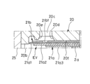
- the extension side sub-valve EV as a damping valve comprises a valve seat member 20, a valve body 21, a spacer 22, and a valve stopper 23, as shown in Figure 2.
- the valve seat member 20 is annular and includes a partition body 20a in the shape of a disk with a hole that fits onto the outer periphery of the small diameter portion 2a, an annular opposing seat portion 20b that protrudes downward from the outer periphery of the lower end of the partition body 20a in FIG. 2, a plurality of ports 20c that are provided on the same circumference and on the inner side of the opposing seat portion 20b at the lower end of the partition body 20a in FIG.
- a window 20d that is an annular recess that is connected to the outlet end of each port 20c at the lower end of the partition body 20a in FIG. 2, an annular valve seat 20e that protrudes downward from between the opposing seat portion 20b and the port 20c at the lower end of the partition body 20a in FIG. 2, and an annular inner seat portion 20f that is provided on the inner periphery of the window 20d.
- the opposing seat 20b surrounds the outer periphery of the annular valve seat 20e with a gap from the partition body 20a, and protrudes downward from the lower end of the annular valve seat 20e.
- the height of the opposing seat 20b is higher than the annular valve seat 20e when viewed from the partition body 20a, and the height difference between the opposing seat 20b and the annular valve seat 20e is at least higher than the total axial thickness of the backup valve 21b of the valve body 21 and the annular plate 21a1 of the leaf valve 21a, which will be described later.
- the annular valve seat 20e is provided on the inner circumference side, which is the fixed end side of the valve body 21, in the radial direction, relative to the opposing seat 20b in the valve seat member 20.
- the height of the seat surface that is the lower end surface of the inner circumference seat 20f in FIG. 2 is higher than the height of the seat surface that is the lower end surface of the annular valve seat 20e in FIG. 2, and is lower than the opposing seat 20b.
- the opposing seat 20b and the annular valve seat 20e protrude in the axial direction relative to the partition body 20a, and an annular recess is formed between the opposing seat 20b and the annular valve seat 20e.
- the annular valve seat 20e is provided on the inner circumference side of the opposing seat 20b, and the height of the opposing seat 20b is higher than the annular valve seat 20e as described above, the opposing seat 20b and the annular valve seat 20e may be integrally provided to protrude in the axial direction from the partition body 20a without having an annular recess between them.
- the valve body 21 is made up of multiple annular plates and includes a leaf valve 21a, the inner periphery of which is fixed to the small diameter portion 2a as a fixed end and the outer periphery of which is allowed to flex as a free end, and a backup valve 21b, which is stacked on the valve seat member side of the leaf valve 21a, and is stacked on the lower end of the partition body 20a of the valve seat member 20 in FIG. 2 and fixed to the outer periphery of the small diameter portion 2a.
- the leaf valve 21a is composed of three elastic annular plates 21a1, 21a2, and 21a3, each of which has an inner diameter set to a diameter that can fit around the outer periphery of the small diameter portion 2a.
- the leaf valve 21a is composed of the elastic annular plate 21a1, which is located at the top in FIG. 2 and has the largest outer diameter, the annular plate 21a2, which has an outer diameter smaller than that of the annular plate 21a1 and is stacked on the side opposite the valve seat member of the annular plate 21a1, and the annular plate 21a3, which has an outer diameter smaller than that of the annular plate 21a2 and is stacked on the side opposite the valve seat member of the annular plate 21a2.
- the number of annular plates constituting the leaf valve 21a can be changed as appropriate depending on the desired damping force characteristics, and may be one.
- the backup valve 21b is stacked on the valve seat member side, which is the upper side in FIG. 2, of the annular plate 21a1, which has the largest outer diameter of the leaf valve 21a, and is an annular plate whose outer diameter is smaller than that of the annular plate 21a1 and whose inner diameter is equal to that of the annular plate 21a1.
- the outer diameter of the backup valve 21b is larger than the inner diameter of the seat surface at the lower end of the annular valve seat 20e.
- the inner peripheral seat 20f is higher than the annular valve seat 20e, so that the valve body 21 faces the annular valve seat 20e in the axial direction, forming a gap in the axial direction between the backup valve 21b and the annular valve seat 20e, and the outer peripheral surface of the free end of the annular plate 21a1, which has the largest outer diameter in the leaf valve 21a, faces the inner peripheral surface of the opposing seat 20b of the valve seat member 20 in the radial direction via a small gap.
- the gap between the leaf valve 21a and the opposing seat 20b is extremely small, making it difficult for liquid to pass through the gap, and this state is defined as the state in which the extension side sub-valve EV is closed.
- the expansion side sub-valve EV can open and close the port 20c, so it is not necessary for the entire outer peripheral surface of the annular plate 21a1 to face the entire inner peripheral surface of the opposing seat portion 20b in the radial direction.
- the spacer 22 stacked on the side opposite the valve seat member of the valve body 21 has an outer diameter smaller than that of the annular plate 21a3 arranged on the side closest to the valve seat member of the leaf valve 21a, and is fixed immovably to the small diameter portion 2a.
- the spacer 22 is composed of one annular plate, but may be composed of multiple annular plates. Therefore, when the leaf valve 21a and the backup valve 21b of the valve body 21 receive pressure from the upper part of the valve seat member 20 in FIG. 2, which tries to pass through the port 20c downward, the outer periphery of the spacer 22 is deflected downward in FIG. 2 with the outer periphery of the spacer 22 as a fulcrum.
- the outer periphery of the leaf valve 21a is no longer directly opposite the inner periphery of the opposing seat portion 20b in the radial direction, and is shifted downward with respect to the opposing seat portion 20b, and the area of the flow path formed by the gap between the leaf valve 21a and the opposing seat portion 20b is increased according to the amount of deflection of the leaf valve 21a.
- the expansion side sub-valve EV opens, and the expansion side sub-valve EV provides resistance to the flow of liquid while allowing the liquid to flow through the gap via the valve body 21.
- the leaf valve 21a and backup valve 21b of the valve body 21 When the leaf valve 21a and backup valve 21b of the valve body 21 receive pressure from the lower part of the valve seat member 20 in FIG. 2 and attempt to pass through the port 20c in an upward direction, the leaf valve 21a and backup valve 21b bend the outer periphery upward in FIG. 2 with the inner periphery of the inner periphery seat portion 20f of the valve seat member 20 as a fulcrum. When the valve body 21 bends by a preset amount or more, the backup valve 21b seats on the annular valve seat 20e and closes the port 20c. In this way, when the liquid flows from the upper part of the port 20c in FIG.
- the extension side sub-valve EV as a damping valve bends the free end of the valve body 21 toward the opposite side of the valve seat member to open the valve, allowing the liquid to flow. Conversely, when the liquid flows from the lower part of the port 20c in FIG. 2 to the upper part, the free end of the valve body 21 bends toward the valve seat member to seat on the annular valve seat 20e and block the liquid flow.
- the extension side sub-valve EV functions as a damping valve that opens to allow the flow of liquid flowing in one direction through the port 20c while providing resistance, and conversely, it can also function as a check valve that closes to prevent the flow of liquid flowing in the other direction through the port 20c.
- the backup valve 21b overlaps the valve seat member side of the leaf valve 21a, and when the valve body 21 sits on the annular valve seat 20e, it abuts against the valve seat side of the leaf valve 21a to support the leaf valve 21a, and restricts the portion of the leaf valve 21a between the annular valve seat 20e and the inner peripheral seat portion 20f from bending upward toward the valve seat member side due to pressure from below.
- the backup valve 21b supports the leaf valve 21a and suppresses the leaf valve 21a from bending significantly toward the valve seat member side when the valve body 21 sits on the annular valve seat 20e, preventing excessive stress from acting on the leaf valve 21a and protecting the leaf valve 21a.
- the expansion side sub-valve EV allows liquid to flow from the lower side to the upper side through the port 20c until the valve element 21 bends toward the valve seat member and seats on the annular valve seat 20e.
- the amount of bending until the valve element 21 abuts on the annular valve seat 20e when functioning as a check valve can be adjusted by setting the height of the seating surfaces of the inner circumferential seat portion 20f and the annular valve seat 20e, but the amount of bending may also be adjusted by interposing a spacer between the inner circumferential seat portion 20f and the valve element 21.
- the height of the seating surface of the inner circumferential seat portion 20f may be made lower than the height of the seating surface of the annular valve seat 20e, and the amount of bending may be adjusted by the number of stacked spacers.
- valve stopper 23 is laminated on the side of the spacer 22 opposite the valve seat member, and when the valve body 21 is significantly deflected, it comes into contact with at least one of the annular plates 21a1, 21a2, and 21a3 of the valve body 21 to support the valve body 21 and prevent excessive stress from acting on the valve body 21, thereby protecting the valve body 21.
- a spacer 24 is stacked below the valve stopper 23 in FIG. 2.
- the spacer 24 is formed in a bottomed cylindrical shape, with a hole 24a at the bottom that allows the small diameter portion 2a of the rod 2 to pass through, and a notch 24c that connects the inside and outside of the cylindrical portion 24b.
- the cylindrical portion 24b faces radially through holes 2e and 2f in the small diameter portion 2a, and the inside of the cylindrical portion 24b is connected to the inside of the rod 2. Since the spacer 24 is arranged on the side opposite the valve seat member of the valve body 21, the upper end of the spacer 24 may be used as a valve stopper and the valve stopper 23 may be eliminated.
- the partition member 25 is cylindrical with a bottom, and has a hole 25a at the bottom that allows the small diameter portion 2a of the rod 2 to pass through.
- the open side faces upward and is placed on the lower end of the spacer 24 in FIG. 2, and the cylindrical portion is fitted into the outer periphery of the valve seat member 20 to be fixed to the outer periphery of the small diameter portion 2a of the rod 2.
- the partition member 25 has an outer diameter smaller than the inner diameter of the cylinder 1, and forms an annular gap between the cylinder 1 and the partition member 25, and separates the space R3 within the expansion side chamber R1 together with the valve seat member 20.
- the space R3 is connected to the expansion side chamber R1 via a port 20c provided in the valve seat member 20, and is connected to the compression side chamber R2 through the notch 24c of the spacer 24, the through holes 2e and 2f of the small diameter portion 2a, and the inside of the rod 2.
- the port 20c, the space R3, the through holes 2e, 2f, and the inside of the rod 2 form an expansion-side sub-passage EP as a damping passage that connects the expansion-side chamber R1 and the compression-side chamber R2.
- the expansion-side sub-passage EP thus configured connects the expansion-side chamber R1 and the compression-side chamber R2 in parallel with the expansion-side passage 3a provided in the piston 3. Therefore, the expansion-side sub-valve EV is provided in the expansion-side sub-passage EP that bypasses the expansion-side passage 3a and connects the expansion-side chamber R1 and the compression-side chamber R2.
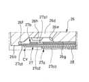
- the compression side sub-valve CV as a damping valve is disposed between the partition member 25 and the compression side main valve 5 and is attached to the outer periphery of the small diameter portion 2a.
- the compression side sub-valve CV includes a valve seat member 26, a valve body 27, a spacer 28, and a valve stopper 29.
- the valve seat member 26 is annular and includes a perforated disk-shaped partition body 26a that fits onto the outer periphery of the small diameter portion 2a, an annular opposing seat portion 26b that protrudes downward from the outer periphery of the lower end of the partition body 26a in FIG. 2, an annular groove 26c provided on the inner periphery of the partition body 26a, a plurality of ports 26d that open from the inner periphery side of the opposing seat portion 26b at the lower end of the partition body 26a in FIG. 2 and communicate with the annular groove 26c, and It is equipped with a window 26e, which is an annular recess at the lower end in FIG.
- annular valve seat 26f that is provided at the lower end of the partition body 26a in FIG. 2 between the opposing seat 26b and the port 26d and protrudes downward
- annular inner seat 26g provided on the inner periphery of the window 26e
- multiple restriction portions 26h that protrude in the axial direction from within the window 26e of the partition body 26a.
- the opposing seat 26b surrounds the outer periphery of the annular valve seat 26f and protrudes downward from the lower end of the annular valve seat 26f.
- the height of the opposing seat 26b is higher than the annular valve seat 26f when viewed from the partition body 26a, and the height difference between the opposing seat 26b and the annular valve seat 26f is at least higher than the total axial thickness of the backup valve 27b of the valve body 27 and the annular plate 27a1 of the leaf valve 27a, which will be described later.
- the annular valve seat 26f is provided on the inner circumference side that is the fixed end side of the valve body 27 in the radial direction with respect to the opposing seat 26b in the valve seat member 26.
- the height of the seat surface that is the lower end surface of the inner circumference seat 26g in FIG. 2 is higher than the height of the seat surface that is the lower end surface of the annular valve seat 26f in FIG. 2, and is lower than the opposing seat 26b.
- the opposing seat 26b and the annular valve seat 26f protrude axially from the partition body 26a as one unit, and the annular valve seat 26f is provided adjacent to the inside of the opposing seat 26b.
- the annular valve seat 26f may be spaced apart from the opposing seat 26b on the inner circumference side of the opposing seat 26b and protrude from the partition body 26a.
- valve seat member 26 is provided with a plurality of restricting portions 26h that protrude in the axial direction from the inner circumferential side, which is the lower end of the partition body 26a and is closer to the fixed end of the valve body 27 than the annular valve seat 26f in the radial direction.
- the restricting portions 26h are provided between the annular valve seat 26f and the inner circumferential seat portion 26g and between the ports 26d, 26d in the window 26e in the circumferential direction of the partition body 26a, but the installation position of the restricting portions 26h can be arbitrarily changed in design as long as they are between the annular valve seat 26f and the inner circumferential seat portion 26g and do not interfere with the port 26d.
- the shape of the restricting portions 26h when the valve seat member 26 is viewed in the axial direction may be arc-shaped or circular, and can be arbitrarily changed in design.
- the restricting portion 26h is provided between the ports 26d, 26d, in order to avoid the port 26d, but it is preferable to provide the restricting portion 26h at equal intervals on the same circumference in order to uniformly support the valve body 27 in the circumferential direction when the valve body 27 is deflected toward the valve seat member, but it does not necessarily have to be provided at equal intervals on the same circumference as long as it can support the valve body 27.
- the height of the seat surface of the restricting portion 26h is the same as the seat surface of the annular valve seat 26f, but it may be lower than the annular valve seat 26f as long as the valve body 27 can be supported by abutting against the backup valve 27b when seated on the annular valve seat 26f.
- the valve body 27 is made up of multiple annular plates and includes a leaf valve 27a, the inner periphery of which is fixed to the small diameter portion 2a as a fixed end and the outer periphery of which is allowed to flex as a free end, and a backup valve 27b, which is stacked on the valve seat member side of the leaf valve 27a, and is stacked on the lower end of the partition body 26a of the valve seat member 26 in FIG. 2 and fixed to the outer periphery of the small diameter portion 2a.
- the leaf valve 27a is composed of three elastic annular plates 27a1, 27a2, and 27a3, each of which has an inner diameter set to a diameter that can fit around the outer periphery of the small diameter portion 2a.
- the leaf valve 27a is composed of an elastic annular plate 27a1, which is located at the top in FIG. 2 and has the largest outer diameter; an annular plate 27a2, which has an outer diameter smaller than that of the annular plate 27a1 and is stacked on the side opposite the valve seat member of the annular plate 27a1; and an annular plate 27a3, which has an outer diameter smaller than that of the annular plate 27a2 and is stacked on the side opposite the valve seat member of the annular plate 27a2.
- the backup valve 27b is stacked on the valve seat member side, which is the upper side in FIG. 2 of the annular plate 27a1, which has the largest outer diameter of the leaf valve 27a, and is an annular plate with an outer diameter smaller than the annular plate 27a1 and the annular valve seat 26f and an inner diameter equal to the inner diameter of the annular plate 27a1.
- the outer diameter of the backup valve 27b is smaller than the inner diameter of the seat surface at the lower end of the annular valve seat 26f, so even if the valve body 27 bends toward the valve seat member, it is the annular plate 27a1 of the leaf valve 27a that seats on the annular valve seat 26f.
- the inner circumferential seat 26g is higher than the annular valve seat 26f, so that the valve body 27 faces the annular valve seat 26f in the axial direction, forming a gap in the axial direction between the backup valve 27b and the annular valve seat 26f, and the outer peripheral surface of the free end of the annular plate 27a1, which has the largest outer diameter in the leaf valve 27a, faces directly in the radial direction with a small gap interposed between the inner circumferential surface of the opposing seat 26b of the valve seat member 26.
- the gap between the leaf valve 27a and the opposing seat 26b is extremely small, making it difficult for liquid to pass through the gap, and this state is defined as the state in which the compression side sub-valve CV is closed.
- the compression side sub-valve CV can open and close the port 26d, so it is not necessary for the entire outer peripheral surface of the annular plate 27a1 to face the entire inner peripheral surface of the opposing seat portion 26b in the radial direction.
- the spacer 28 stacked on the side opposite the valve seat member of the valve body 27 has an outer diameter smaller than that of the annular plate 27a3 arranged on the side closest to the valve seat member of the leaf valve 27a, and is fixed immovably to the small diameter portion 2a.
- the spacer 28 is composed of one annular plate, but may be composed of multiple annular plates. Therefore, when the leaf valve 27a and the backup valve 27b of the valve body 27 receive pressure from the upper side of the valve seat member 26 in FIG. 2 and attempt to pass through the port 26d downward, the outer periphery of the spacer 28 is deflected downward in FIG. 2 with the outer periphery of the spacer 28 as a fulcrum.
- the outer periphery of the leaf valve 27a no longer faces the inner periphery of the opposing seat portion 26b in the radial direction, and shifts downward with respect to the opposing seat portion 26b, and the area of the flow path formed by the gap between the leaf valve 27a and the opposing seat portion 26b is increased according to the amount of deflection of the leaf valve 27a.
- the compression side sub-valve CV opens, and the compression side sub-valve CV provides resistance to the flow of liquid while allowing the liquid to flow through the gap via the valve body 27.
- the leaf valve 27a and backup valve 27b of the valve body 27 When the leaf valve 27a and backup valve 27b of the valve body 27 receive pressure from the lower part of the valve seat member 26 in FIG. 2 and attempt to pass through the port 26d upward, the leaf valve 27a and backup valve 27b of the valve body 27 bend the outer periphery upward in FIG. 2 with the inner periphery of the inner periphery seat portion 26g of the valve seat member 26 as a fulcrum.
- the annular plate 27a1 of the leaf valve 27a seats on the annular valve seat 26f and closes the port 26d. In this way, when the liquid flows from the upper part of the port 26d to the lower part in FIG.
- the free end of the valve body 27 bends toward the opposite side of the valve seat member to open the valve, allowing the liquid to flow. Conversely, when the liquid flows from the lower part of the port 26d to the upper part in FIG. 2, the free end of the valve body 27 bends toward the valve seat member to seat on the annular valve seat 26f and block the liquid flow.
- the contraction side sub-valve CV functions as a damping valve that opens to allow the flow of liquid through the port 26d in one direction while providing resistance to the flow, and conversely, functions as a check valve that closes to prevent the flow of liquid through the port 26d in the other direction.
- the backup valve 27b overlaps the leaf valve 27a on the valve seat member side, and when the leaf valve 27a sits on the annular valve seat 26f, it abuts against the valve seat side surface of the leaf valve 27a to support the leaf valve 27a, and restricts the portion of the leaf valve 27a between the annular valve seat 26f and the inner peripheral seat portion 26g from bending upward toward the valve seat member side due to pressure from below.
- the backup valve 27b supports the leaf valve 27a and suppresses the leaf valve 27a from bending significantly toward the valve seat member side when the valve body 27 sits on the annular valve seat 26f, thereby preventing excessive stress from acting on the leaf valve 27a and protecting the leaf valve 27a.
- valve seat member 26 in the compression side sub-valve CV is provided with, in addition to the configuration of the expansion side sub-valve EV, a restricting portion 26h which faces the valve element 27 in the axial direction on the inner circumferential side of the annular valve seat 26f and which restricts the bending between the annular valve seat 26f and the fixed end of the valve element 27 when an intermediate portion between a portion of the valve element 27 that abuts against the annular valve seat 26f and a portion of the valve element 27 that abuts against the inner circumferential seat portion 26g bends by a predetermined amount or more.
- the bending of the intermediate portion of the leaf valve 27a can be suppressed not only by the backup valve 27b but also by the restricting portion 26h, so that fatigue of the leaf valve 27a can be further reduced.
- the height of the restricting portion 26h and the annular valve seat 26f need only be set so that the restricting portion 26h does not interfere with the valve body 27's ability to seat on or leave the annular valve seat 26f.
- the amount of deflection of the valve body 27 when it abuts against the restricting portion 26h can be set arbitrarily, but the amount should be set so that the restricting portion 26h can support the valve body 27 before the stress on the valve body 27 becomes excessive.
- the compression side sub-valve CV allows liquid to flow from the lower side to the upper side through the port 26d until the valve element 27 bends toward the valve seat member and seats on the annular valve seat 26f.
- the amount of deflection which is the amount of deflection until the valve element 27 abuts on the annular valve seat 26f when functioning as a check valve, can be adjusted by setting the height of the seating surfaces of the inner circumferential seat portion 26g and the annular valve seat 26f, but the amount of deflection may also be adjusted by interposing a spacer between the inner circumferential seat portion 26g and the valve element 27.
- the height of the seating surface of the inner circumferential seat portion 26g may be made lower than the height of the seating surface of the annular valve seat 26f, and the amount of deflection may be adjusted by the number of stacked spacers.
- valve stopper 29 is laminated on the side of the spacer 28 opposite the valve seat member, and when the valve body 27 is significantly deflected, it comes into contact with at least one of the annular plates 27a1, 27a2, and 27a3 of the valve body 27 to support the valve body 27 and prevent excessive stress from acting on the valve body 27, thereby protecting the valve body 27.
- the annular groove 26c formed on the inner periphery of the valve seat member 26 faces the through holes 2g, 2h provided in the small diameter portion 2a in the radial direction, so that the port 26d is connected to the inside of the rod 2. Therefore, the expansion side chamber R1 is connected to the compression side chamber R2 through the port 26d, the through holes 2g, 2h, and the inside of the rod 2.
- the port 26d, the through holes 2g, 2h, and the inside of the rod 2 form a compression side sub-passage CP as a damping passage that connects the expansion side chamber R1 and the compression side chamber R2.
- the compression side sub-passage CP configured in this manner is parallel to the compression side passage 3b provided in the piston 3 and connects the expansion side chamber R1 and the compression side chamber R2. Therefore, the compression side sub-valve CV is provided in the compression side sub-passage CP that bypasses the compression side passage 3b and connects the expansion side chamber R1 to the compression side chamber R2.
- a cylindrical rotary valve 12 is housed within the rod 2, with its outer circumferential surface in sliding contact with the inner circumferential surface of the rod 2, allowing it to rotate circumferentially within the rod 2.
- the rotary valve 12 has holes 12a, 12b, 12c, and 12d that communicate between the inside and outside at positions that can face the through holes 2e, 2f, 2g, and 2h, respectively, and when rotated by a control rod 13 inserted into the rod 2, the degree of communication between the through holes 2e and 12a, the through holes 2f and 12b, the through holes 2g and 12c, and the through holes 2h and 12d can be changed, and the through holes 2e, 2f, 2g, and 2h can be blocked without facing the holes 12a, 12b, 12c, and 12d.
- the rotary valve 12 can adjust the area of each of the four flow passages consisting of the through hole 2e and the hole 12a, the through hole 2f and the hole 12b, the through hole 2g and the hole 12c, and the through hole 2h and the hole 12d depending on the circumferential rotation position relative to the rod 2, and can adjust the resistance to the flow of hydraulic oil passing through the flow passages.
- the control rod 13 is driven by a rotary actuator (not shown), such as a stepping motor attached to the tip of the rod 2, but the rotary actuator may be housed within the rod 2.
- the rotary valve 12 is provided in the middle of the expansion-side sub-passage EP and the compression-side sub-passage CP, and when rotated by the control rod 13, the degree of communication (flow path area) between the holes 12a, 12b, 12c, 12d and the corresponding through holes 2e, 2f, 2g, 2h can be changed to change the resistance to the flow of liquid passing through the expansion-side sub-passage EP and the compression-side sub-passage CP.
- the rotary valve 12 has two holes 12a, 12b for adjusting the flow area of the expansion-side sub-passage EP and two holes 12c, 12d for adjusting the flow area of the compression-side sub-passage CP, but the number of holes can be changed as desired according to the setting of the maximum flow area.
- the number of through holes provided in the rod 2 may be set in accordance with the number of holes provided in the rotary valve 12.
- the holes 12a, 12b, 12c, and 12d provided in the rotary valve 12 may be offset in the circumferential direction, and the through holes 2e, 2f, 2g, and 2h provided in the rod 2 may be provided at appropriate positions corresponding to the holes 12a, 12b, 12c, and 12d.
- the hole 12b and the through hole 2f may be connected when the hole 12a and the through hole 2e provided in the middle of the expansion side sub-passage EP face each other and communicate with each other, or the hole 12b and the through hole 2f may be set to face each other at a timing different from the timing when the hole 12a and the through hole 2e face each other. This also applies to the relationship between the holes 12c, 12d and the through holes 2g, 2h provided in the middle of the compression side sub-passage CP.
- the damping valves, EV (rebound side sub-valve) and CV (compression side sub-valve), and D (shock absorber) are configured as described above.
- the operation of D (rebound side sub-valve) and CV (compression side sub-valve), and D (shock absorber) is described below.
- the piston 3 moves upward in the cylinder 1 in FIG. 1 to compress the expansion-side chamber R1.
- the expansion-side sub-passage EP and the compression-side sub-passage CP are in communication with each other through the rotary valve 12, the liquid in the expansion-side chamber R1 compressed by the upward movement of the piston 3 tries to move to the expanding compression-side chamber R2 through the expansion-side sub-passage EP together with the expansion-side passage 3a provided in the piston 3.
- the expansion speed of the shock absorber D when the expansion speed of the shock absorber D is in the extremely low speed range and close to 0, the pressure in the expansion-side chamber R1 rises, but the differential pressure between the pressure in the expansion-side chamber R1 and the pressure in the compression-side chamber R2 does not reach the opening pressure of the expansion-side main valve 4, so the expansion-side main valve 4 does not open and keeps the expansion-side passage 3a closed.
- the compression-side main valve 5 receives the pressure of the expansion-side chamber R1 from the back side and closes the compression-side passage 3b.
- valve body 27 remains closed by opposing the outer circumferential surface of the annular plate 27a1 in the leaf valve 27a within the axial width range of the inner circumference of the opposing seat 26b, and the flow path area in the annular gap between the valve body 27 and the opposing seat 26b is kept extremely small.
- the extension side main valve 4 also keeps the extension side passage 3a closed. Therefore, when the extension speed of the shock absorber D is in the very low speed range and close to 0, the characteristic of the damping force generated in relation to the piston speed of the shock absorber D (damping force characteristic) rises sharply as shown in Figure 3.
- valve body 27 in the contraction side sub-valve CV bends under the pressure in the expansion side chamber R1 and seats on the annular valve seat 26f of the valve seat member 26, closing the port 26d and preventing the liquid from passing through the contraction side sub-passage CP.
- valve body 21 bends significantly and abuts against the valve stopper 23, maximizing the flow area in the annular gap between the opposing seat 20b, while the extension-side main valve 4 bends and moves away from the piston 3 to open the extension-side passage 3a.
- the liquid moves from the extension-side chamber R1 to the compression-side chamber R2 through the gap between the extension-side main valve 4 and the piston 3, and the increase in piston speed increases the amount of bending of the extension-side main valve 4, and the flow area in the gap between the extension-side main valve 4 and the piston 3 becomes larger than the flow area in the annular gap between the valve body 21 and the opposing seat 20b in the extension-side sub-valve EV. Therefore, the shock absorber D generates a damping force mainly due to the resistance that the extension-side main valve 4 provides to the flow of liquid.
- the damping force characteristic of the shock absorber D becomes a characteristic that generates a damping force with a slope that is almost constant with respect to the increase in piston speed as shown in FIG. 3.
- the resistance to the flow of liquid passing through the extension side sub-passage EP can be adjusted, so the damping force of the shock absorber D in this embodiment can be adjusted.
- leaf valve 27a in valve body 27 in compression-side sub-valve CV is pressed upward by the pressure in the expansion-side chamber R1, but since the outer circumferential side is supported by annular valve seat 26f and the inner circumferential side is supported by inner circumferential seat portion 26g, the intermediate portion of leaf valve 27a between the portion abutting annular valve seat 26f and the portion abutting inner circumferential seat portion 26g bends so as to be convex toward the upper side in Fig. 2.
- the backup valve 27b abuts against the valve seat member side of the leaf valve 27a to support the leaf valve 27a, and suppresses the bending of the middle part of the leaf valve 27a, suppressing the bending deformation of the middle part of the leaf valve 27a to be convex upward, reducing the stress acting on the leaf valve 27a and suppressing fatigue of the leaf valve 27a.
- valve body 27 when the valve body 27 is pressed by the pressure in the expansion side chamber R1 and the backup valve 27b abuts against the restricting portion 26h of the valve seat member 26, it is supported by the restricting portion 26h and prevents the bending of the middle part of the leaf valve 27a from becoming larger, and the stress of the leaf valve 27a does not increase any more, further suppressing fatigue of the leaf valve 27a.
- the contraction speed of the shock absorber D when the contraction speed of the shock absorber D is in the extremely low speed range and close to 0, the pressure in the compression side chamber R2 rises, but the pressure difference between the pressure in the compression side chamber R2 and the pressure in the expansion side chamber R1 does not reach the opening pressure of the compression side main valve 5, so the compression side main valve 5 does not open and keeps the compression side passage 3b closed.
- the expansion side main valve 4 receives the pressure of the compression side chamber R2 from the back side and closes the expansion side passage 3a.
- valve body 21 remains closed by opposing the outer circumferential surface of the annular plate 21a1 in the leaf valve 21a within the axial width range of the inner circumference of the opposing seat 20b, and the flow path area in the annular gap between the valve body 21 and the opposing seat 20b is kept extremely small.
- valve body 21 in the expansion side sub-valve EV bends under the pressure in the compression side chamber R2 and seats on the annular valve seat 20e of the valve seat member 20, closing the port 20c and preventing the liquid from passing through the expansion side sub-passage EP.
- valve body 27 bends significantly and abuts against the valve stopper 29, maximizing the flow path area in the annular gap between the opposing seat 26b, while the compression side main valve 5 bends and moves away from the piston 3 to open the compression side passage 3b.
- the liquid moves from the compression side chamber R2 to the extension side chamber R1 through the gap between the compression side main valve 5 and the piston 3, and the increase in piston speed increases the amount of bending of the compression side main valve 5, and the flow path area in the gap between the compression side main valve 5 and the piston 3 becomes larger than the flow path area in the annular gap between the valve body 27 and the opposing seat 26b in the compression side sub-valve CV. Therefore, the shock absorber D generates a damping force mainly due to the resistance that the compression side main valve 5 provides to the flow of liquid.
- the damping force characteristic of the shock absorber D becomes a characteristic that generates a damping force with a slope that is almost constant with respect to the increase in piston speed, as shown in FIG. 3.
- the resistance to the flow of liquid passing through the compression side sub-passage CP can be adjusted, so the damping force of the shock absorber D in this embodiment can be adjusted.
- the leaf valve 21a in the valve body 21 of the expansion side sub-valve EV is pressed upward by the pressure in the compression side chamber R2, but since the outer circumferential side is supported by the annular valve seat 20e and the inner circumferential side is supported by the inner circumferential seat portion 20f, the intermediate portion between the portion of the leaf valve 21a that abuts against the annular valve seat 20e and the portion that abuts against the inner circumferential seat portion 20f bends so as to be convex toward the upper side in Fig. 2.
- the backup valve 21b abuts against the valve seat member side of the leaf valve 21a to support the leaf valve 21a, suppressing the bending of the middle part of the leaf valve 21a, thereby suppressing the bending deformation of the middle part of the leaf valve 21a that becomes convex upward, reducing the stress acting on the leaf valve 21a and suppressing fatigue of the leaf valve 21a.
- the extension side sub-valve EV and the compression side sub-valve CV as damping valves in this embodiment include an annular valve body 21, 27 having an inner periphery as a fixed end and an outer periphery as a free end that is allowed to bend relative to the fixed end, an annular opposing seat portion 20b, 26b that is annular and faces at least a part of the peripheral surface on the free end side of the valve body 21, 27, a port 20c, 26d that is provided radially closer to the fixed end of the valve body 21, 27 than the opposing seat portion 20b, 26b, and an opposing seat portion 20b.
- valve bodies 21, 27 are provided with annular leaf valves 21a, 27a and annular backup valves 21b, 27b that are overlapped on the valve seat member side of the leaf valves 21a, 27a to suppress bending of the free ends of the leaf valves 21a, 27a toward the valve seat member side.
- valve bodies 21, 27 When the valve bodies 21, 27 receive pressure from the ports 20c, 26d, the valve bodies 21, 27 bend to open the ports 20c, 26d and provide resistance to the flow of liquid passing through the ports 20c, 26d.
- the valve bodies 21, 27 When the valve bodies 21, 27 receive pressure pressing toward the valve seat members 20, 26, the valve bodies 21, 27 seat on the annular valve seats 20e, 26f to block the ports 20c, 26d. Therefore, they function as damping valves for the flow of liquid attempting to pass through the ports 20c, 26d in one direction and as check valves for the flow of liquid attempting to pass through the ports 20c, 26d in the other direction.
- the backup valves 21b, 27b contact the valve seat members of the leaf valves 21a, 27a to support the leaf valves 21a, 27a and suppress bending of the middle portions of the leaf valves 21a, 27a. This reduces the stress acting on the leaf valves 21a, 27a and suppresses fatigue of the leaf valves 21a, 27a.
- the extension side sub-valve EV and the compression side sub-valve CV as damping valves in this embodiment can function as check valves while suppressing fatigue of the leaf valves 21a, 27a.
- the backup valves 21b, 27b reduce the momentum of the leaf valves 21a, 27a as they return, preventing the leaf valves 21a, 27a from colliding forcefully with the annular valve seats 20e, 26f, thereby suppressing the generation of abnormal noise.
- the leaf valve 21a bends toward the valve seat member 20 due to pressure from the back side, it is supported by the backup valve 21b, so the amount of bending is reduced, and the leaf valve 21a bends toward the valve seat member 20, thereby suppressing sudden pressure fluctuations in the compression side chamber R2.
- the inner circumferential side of the valve body 21, 27 is the fixed end and the outer circumferential side is the free end, and the outer circumferential surface of the valve body 21, 27 is opposed to the inner circumferential surface of the opposing seat portion 20b, 26b to form the extension side sub-valve EV and the compression side sub-valve CV as damping valves.
- the damping valve may also be formed by setting the outer circumferential side of the valve body as the fixed end and the inner circumferential side as the free end, providing an opposing seat portion on the inner circumferential side of the valve body, and opposing the inner circumferential surface of the valve body to the outer circumferential surface of the opposing seat portion.
- valve seat member 26 in the compression side sub-valve CV as a damping valve in this embodiment is provided with a restricting portion 26h that is disposed radially closer to the fixed end of the valve body 27 than the annular valve seat 26f, faces the valve body 27 in the axial direction, and abuts against the valve body 27 when the free end of the valve body 27 bends toward the valve seat member by a predetermined amount or more to restrict the bending of the valve body 27.
- the outer diameter of the backup valve 27b is smaller than the inner diameter of the annular valve seat 26f, and only the leaf valve 27a is able to seat and separate from the annular valve seat 26f in the axial direction, and the backup valve 27b cannot abut against the annular valve seat 26f; however, the outer diameter of the backup valve 27b may be made larger so that when the valve body 27 bends toward the valve seat member, the backup valve 27b seats on the annular valve seat 26f and blocks port 26d.
- the outer diameter of the backup valve 21b is larger than the inner diameter of the annular valve seat 20e, and both the backup valve 21b and the leaf valve 21a face the annular valve seat 20e in the axial direction.
- the backup valve 21b seats on the annular valve seat 20e and closes the port 20c.
- the outer diameter of the backup valve 21b may be made smaller than the inner diameter of the annular valve seat 20e so that the leaf valve 21a can be seated and removed from the annular valve seat 20e.
- the backup valve 21b has a notch 21b1 that penetrates the wall thickness in the axial direction and faces the leaf valve 21a, liquid can easily enter between the leaf valve 21a and the backup valve 21b through the notch 21b1, and sticking between the leaf valve 21a and the backup valve 21b can be suppressed. Therefore, with the extension side sub-valve EV configured in this way as a damping valve, the valve body 21 can bend smoothly when it starts to bend, and a sudden change in damping force characteristics can be prevented.
- the notches 21b1 may be provided in any shape and in any number as long as they are provided in a manner that can prevent the passage of liquid when the valve body 21 abuts against the annular valve seat 20e.
- the notch 27b1 is provided even when the backup valve 27b abuts against the regulating portion 26h, and liquid can easily enter between the leaf valve 27a and the backup valve 27b and between the regulating portion 26h and the backup valve 27b through the notch 27b1, thereby preventing sticking between the leaf valve 27a and the backup valve 27b and between the regulating portion 26h and the backup valve 27b.
- the valve element 27 can bend smoothly when it starts to bend, preventing a sudden change in the damping force characteristics, and also enabling the valve element 27 to return quickly when it returns in a direction away from the valve seat member 26 from a state in which the backup valve 27b abuts against the restricting portion 26h, thereby preventing a delay in opening the port 26d.
- the notch 27b1 may be provided in a manner that can prevent the passage of liquid when the valve element 27 abuts against the annular valve seat 26f, but is preferably provided so as not to be closed by the restricting portion 26h when the backup valve 27b abuts against the restricting portion 26h.
- the shock absorber D of this embodiment is equipped with a cylinder (outer tube) 1, a rod 2 inserted into the cylinder (outer tube) 1 so as to be axially movable, a shock absorber body A having at least an extension side chamber (working chamber) R1 and a compression side chamber (working chamber) R2 through which liquid flows as the rod 2 moves relative to the cylinder (outer tube) 1, and an extension side sub-valve EV and a compression side sub-valve CV as damping valves provided between the extension side chamber (working chamber) R1 and the compression side chamber (working chamber) R2.
- the expansion side sub-valve EV generates a damping force when the liquid flows from the expansion side chamber R1 to the compression side chamber R2, and closes the expansion side sub-passage EP when the liquid flows from the compression side chamber R2 to the expansion side chamber R1, so that the damping force characteristics of the expansion side of the shock absorber D can be set independently.
- the compression side sub-valve CV generates a damping force when the liquid flows from the compression side chamber R2 to the expansion side chamber R1, and closes the compression side sub-passage CP when the liquid flows from the expansion side chamber R1 to the compression side chamber R2, so that the damping force characteristics of the compression side of the shock absorber D can be set independently.
- the expansion side sub-valve EV and the compression side sub-valve CV as damping valves increase the damping coefficient in the very low speed range of the expansion/contraction speed to quickly raise the damping force in response to the switching of the expansion/contraction stroke, and can reduce the damping coefficient in the low speed range compared to the very low speed range, so that the damping force characteristics suitable for suppressing the vibration of the vehicle body in the vehicle can be realized, and the ride comfort in the vehicle can be improved.
- the extension side sub-valve EV and the compression side sub-valve CV as damping valves are provided in the extension side sub-passage EP and the compression side sub-passage CP that bypass the extension side passage 3a and the compression side passage 3b of the piston 3, and the damping valves are arranged in parallel with the extension side main valve 4 and the compression side main valve 5 of the piston 3, but the damping valves may be used as the extension side main valve or the compression side main valve.
- the extension side sub-valve EV and the compression side sub-valve CV as damping valves are provided in the extension side sub-passage EP and the compression side sub-passage CP that bypass the extension side passage 3a and the compression side passage 3b of the piston 3, but only the extension side sub-valve EV or only the compression side sub-valve CV may be provided in the shock absorber D.
- the two working chambers are the expansion side chamber R1 and the compression side chamber R2, but if the shock absorber D is a twin-tube shock absorber that has an outer shell as an outer tube around the outer periphery of the cylinder and a reservoir between the cylinder and the outer shell, a damping valve may be provided between the compression side chamber and the reservoir. Therefore, the port in the damping valve may connect the expansion side chamber R1 and the compression side chamber R2, or may connect the compression side chamber and the reservoir.
- the speed range in which damping force is generated mainly by the extension side sub-valve EV and the compression side sub-valve CV as damping valves is the low speed range, but the speeds that divide very low speed, low speed, and high speeds that exceed low speed can be set as desired by the designer.
Landscapes
- Engineering & Computer Science (AREA)
- General Engineering & Computer Science (AREA)
- Mechanical Engineering (AREA)
- Physics & Mathematics (AREA)
- Fluid Mechanics (AREA)
- Fluid-Damping Devices (AREA)
Priority Applications (2)
| Application Number | Priority Date | Filing Date | Title |
|---|---|---|---|
| CN202480016008.9A CN120882988A (zh) | 2023-03-09 | 2024-02-09 | 阻尼阀及缓冲器 |
| DE112024001153.5T DE112024001153T5 (de) | 2023-03-09 | 2024-02-09 | DÄMPFUNGSVENTIL UND STOßDÄMPFER |
Applications Claiming Priority (2)
| Application Number | Priority Date | Filing Date | Title |
|---|---|---|---|
| JP2023036103A JP2024127152A (ja) | 2023-03-09 | 2023-03-09 | 減衰バルブおよび緩衝器 |
| JP2023-036103 | 2023-03-09 |
Publications (1)
| Publication Number | Publication Date |
|---|---|
| WO2024185396A1 true WO2024185396A1 (ja) | 2024-09-12 |
Family
ID=92674600
Family Applications (1)
| Application Number | Title | Priority Date | Filing Date |
|---|---|---|---|
| PCT/JP2024/004470 Ceased WO2024185396A1 (ja) | 2023-03-09 | 2024-02-09 | 減衰バルブおよび緩衝器 |
Country Status (4)
| Country | Link |
|---|---|
| JP (1) | JP2024127152A (https=) |
| CN (1) | CN120882988A (https=) |
| DE (1) | DE112024001153T5 (https=) |
| WO (1) | WO2024185396A1 (https=) |
Citations (5)
| Publication number | Priority date | Publication date | Assignee | Title |
|---|---|---|---|---|
| JPH0276937A (ja) * | 1988-06-03 | 1990-03-16 | Honda Motor Co Ltd | 油圧緩衝器 |
| JP2009222124A (ja) * | 2008-03-14 | 2009-10-01 | Hitachi Ltd | 流体圧緩衝器 |
| JP2013113425A (ja) * | 2011-11-30 | 2013-06-10 | Hitachi Automotive Systems Ltd | 流体圧緩衝器 |
| JP2015086966A (ja) * | 2013-10-31 | 2015-05-07 | 日立オートモティブシステムズ株式会社 | 緩衝器 |
| WO2022215400A1 (ja) * | 2021-04-09 | 2022-10-13 | 日立Astemo株式会社 | 緩衝器 |
-
2023
- 2023-03-09 JP JP2023036103A patent/JP2024127152A/ja active Pending
-
2024
- 2024-02-09 CN CN202480016008.9A patent/CN120882988A/zh active Pending
- 2024-02-09 WO PCT/JP2024/004470 patent/WO2024185396A1/ja not_active Ceased
- 2024-02-09 DE DE112024001153.5T patent/DE112024001153T5/de active Pending
Patent Citations (5)
| Publication number | Priority date | Publication date | Assignee | Title |
|---|---|---|---|---|
| JPH0276937A (ja) * | 1988-06-03 | 1990-03-16 | Honda Motor Co Ltd | 油圧緩衝器 |
| JP2009222124A (ja) * | 2008-03-14 | 2009-10-01 | Hitachi Ltd | 流体圧緩衝器 |
| JP2013113425A (ja) * | 2011-11-30 | 2013-06-10 | Hitachi Automotive Systems Ltd | 流体圧緩衝器 |
| JP2015086966A (ja) * | 2013-10-31 | 2015-05-07 | 日立オートモティブシステムズ株式会社 | 緩衝器 |
| WO2022215400A1 (ja) * | 2021-04-09 | 2022-10-13 | 日立Astemo株式会社 | 緩衝器 |
Also Published As
| Publication number | Publication date |
|---|---|
| CN120882988A (zh) | 2025-10-31 |
| JP2024127152A (ja) | 2024-09-20 |
| DE112024001153T5 (de) | 2025-12-24 |
Similar Documents
| Publication | Publication Date | Title |
|---|---|---|
| JP5812650B2 (ja) | 減衰力調整式緩衝器 | |
| JP7492390B2 (ja) | 緩衝器 | |
| KR102173633B1 (ko) | 완충기 및 이것을 이용한 차량 | |
| US20120160620A1 (en) | Damping force control type shock absorber | |
| JPH10141416A (ja) | 減衰力調整式油圧緩衝器 | |
| JPH1073141A (ja) | 減衰力調整式油圧緩衝器 | |
| JP2004257507A (ja) | 油圧緩衝器 | |
| WO2024185396A1 (ja) | 減衰バルブおよび緩衝器 | |
| JP6626631B2 (ja) | 緩衝器 | |
| WO2024185400A1 (ja) | 減衰バルブおよび緩衝器 | |
| WO2024185398A1 (ja) | 減衰バルブおよび緩衝器 | |
| WO2024185397A1 (ja) | 減衰バルブおよび緩衝器 | |
| JP2024129779A (ja) | ダンパおよびフロントフォーク | |
| JP7506634B2 (ja) | 緩衝器 | |
| JP7269899B2 (ja) | 減衰力調整式緩衝器 | |
| WO2023248694A1 (ja) | 減衰バルブおよび緩衝器 | |
| JP4318071B2 (ja) | 油圧緩衝器 | |
| JPH10274274A (ja) | 減衰力調整式油圧緩衝器 | |
| WO2024190240A1 (ja) | ダンパおよびフロントフォーク | |
| WO2025069878A1 (ja) | 積層リーフバルブおよび緩衝器 | |
| WO2024195429A1 (ja) | 減衰バルブおよび緩衝器 | |
| JP2025018019A (ja) | 減衰バルブおよび緩衝装置 | |
| WO2025192181A1 (ja) | バルブおよび緩衝器 | |
| WO2026079067A1 (ja) | 緩衝器 | |
| WO2026033579A1 (ja) | 緩衝器 |
Legal Events
| Date | Code | Title | Description |
|---|---|---|---|
| 121 | Ep: the epo has been informed by wipo that ep was designated in this application |
Ref document number: 24766769 Country of ref document: EP Kind code of ref document: A1 |
|
| DPE1 | Request for preliminary examination filed after expiration of 19th month from priority date (pct application filed from 20040101) | ||
| WWE | Wipo information: entry into national phase |
Ref document number: 202480016008.9 Country of ref document: CN |
|
| WWE | Wipo information: entry into national phase |
Ref document number: 112024001153 Country of ref document: DE |
|
| WWP | Wipo information: published in national office |
Ref document number: 202480016008.9 Country of ref document: CN |
|
| WWP | Wipo information: published in national office |
Ref document number: 112024001153 Country of ref document: DE |
|
| 122 | Ep: pct application non-entry in european phase |
Ref document number: 24766769 Country of ref document: EP Kind code of ref document: A1 |