WO2024185246A1 - アダプタおよび光接続構造 - Google Patents
アダプタおよび光接続構造 Download PDFInfo
- Publication number
- WO2024185246A1 WO2024185246A1 PCT/JP2023/044046 JP2023044046W WO2024185246A1 WO 2024185246 A1 WO2024185246 A1 WO 2024185246A1 JP 2023044046 W JP2023044046 W JP 2023044046W WO 2024185246 A1 WO2024185246 A1 WO 2024185246A1
- Authority
- WO
- WIPO (PCT)
- Prior art keywords
- ferrule
- optical connector
- adapter
- housing
- connection
- Prior art date
- Legal status (The legal status is an assumption and is not a legal conclusion. Google has not performed a legal analysis and makes no representation as to the accuracy of the status listed.)
- Ceased
Links
Images








Classifications
-
- G—PHYSICS
- G02—OPTICS
- G02B—OPTICAL ELEMENTS, SYSTEMS OR APPARATUS
- G02B6/00—Light guides; Structural details of arrangements comprising light guides and other optical elements, e.g. couplings
- G02B6/24—Coupling light guides
- G02B6/36—Mechanical coupling means
- G02B6/38—Mechanical coupling means having fibre to fibre mating means
-
- G—PHYSICS
- G02—OPTICS
- G02B—OPTICAL ELEMENTS, SYSTEMS OR APPARATUS
- G02B6/00—Light guides; Structural details of arrangements comprising light guides and other optical elements, e.g. couplings
- G02B6/24—Coupling light guides
- G02B6/36—Mechanical coupling means
- G02B6/40—Mechanical coupling means having fibre bundle mating means
Definitions
- the present invention relates to an adapter and an optical connection structure.
- Patent Document 1 discloses an optical connection structure that uses an adapter to connect two optical connectors.
- a good connection state is maintained by pressing the connection end faces of the ferrules of each optical connector against each other with an appropriate biasing force.
- the biasing force is generated by a biasing member biasing the ferrules within the housing of each optical connector.
- the biasing force applied to the ferrules may differ depending on the type of optical connector. In other words, when connecting different types of optical connectors, the biasing force applied to each ferrule may differ. If the biasing force applied to each ferrule differs, the ferrules may be positioned in an inappropriate position (a position that is not the predetermined joint surface). Specifically, a ferrule with a larger biasing force applied is pushed into the ferrule with a smaller biasing force. As a result, a problem may arise in which a good connection state cannot be maintained.
- the present invention was made in consideration of these circumstances, and aims to provide an adapter and optical connection structure that can properly connect two types of optical connectors that have different biasing forces on the ferrules.
- aspect 1 of the present invention is an adapter that connects a first optical connector having a first housing that holds a first ferrule having a first connecting end face therein, and a second optical connector having a second housing that holds a second ferrule having a second connecting end face that has an area smaller than that of the first connecting end face, the adapter having a first insertion opening through which the first housing can be inserted, a second insertion opening through which the second housing can be inserted and that opens in a direction opposite to the first insertion opening, and a connection opening that is disposed between the first insertion opening and the second insertion opening and through which the second ferrule can be inserted, the connection opening having a shape that limits the insertion of the first ferrule.
- Aspect 3 of the present invention is an adapter according to aspect 1, comprising an outer housing having the first insertion opening and the second insertion opening, an inner plate housed in the outer housing and having the connection opening, and an elastic member that biases the inner plate toward the first connection end face, the inner plate having a first contact surface against which the first ferrule contacts, and the elastic member may be compressed between the outer housing and the inner plate.
- Aspect 4 of the present invention is an adapter according to aspect 3, in which the second optical connector is provided with a locking protrusion, the outer housing is provided with a locking hole into which the locking protrusion is engaged, and the dimension from the rear end of the locking hole to the opposing surface of the inner plate opposite the first abutment surface may be greater than the dimension from the portion of the locking protrusion that contacts the locking hole to the tip surface of the second housing.
- Aspect 5 of the present invention is an adapter according to aspect 3 or 4, in which the outer housing has a first outer housing member and a second outer housing member, and the inner plate may be disposed within a space formed by the first outer housing member and the second outer housing member.
- Aspect 7 of the present invention is an optical connection structure according to aspect 6, in which the first optical connector has a first biasing member that biases the first ferrule, and the second optical connector has a second biasing member that biases the second ferrule, and when the first ferrule and the second ferrule are in contact with each other, the biasing force of the first biasing member on the first ferrule may be within a range of 18 to 22 N, and the biasing force of the second ferrule on the second biasing member may be within a range of 7 to 13 N.
- Aspect 8 of the present invention is an optical connection structure according to aspect 7, in which the first optical connector has a protrusion, the adapter has an abutment portion adjacent to the connection opening, abutting the first connection end face, and a locking portion that is locked to the protrusion, and in the axial direction in which the first optical connector and the second optical connector face each other, the distance between the abutment portion and the locking portion may be set so that the biasing force of the first ferrule by the first biasing member is within a range of 18 to 22 N.
- the adapter and optical connection structure according to the above aspect of the present invention allows two types of optical connectors with different biasing forces on the ferrules to be properly connected together.
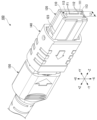
- FIG. 1 is a perspective view of an optical connection structure according to a first embodiment.
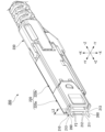
- FIG. 2 is a perspective view of the first optical connector of FIG. 1 .
- FIG. 2 is a perspective view of the second optical connector of FIG. 1 .
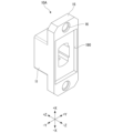
- 2 is a view of a first member of the adapter of FIG. 1 as viewed from a first optical connector side.
- 5 is a cross-sectional view taken along the line VV in FIG. 4.
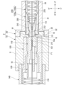
- 6 is a cross-sectional view taken along the line VI-VI in FIG. 7 is a cross-sectional view taken along the line VII-VII of FIG. 1.
- FIG. 6 is a cross-sectional view of a main part of an optical connection structure according to a second embodiment.
- FIG. 6 is a cross-sectional view of a main part of an optical connection structure according to a second embodiment.
- FIG. 9 is a perspective view of the first main body portion of FIG. 8 .
- FIG. 9 is a perspective view of the second main body portion of FIG. 8 .
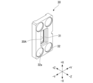
- FIG. 9 is a perspective view of the inner plate of FIG. 8 .
- FIG. 9 is a perspective view of the adapter of FIG. 8 .
- FIG. 9 is a cross-sectional view of a main part of the adapter of FIG. 8 .
- the optical connection structure 1 includes a first optical connector 100, a second optical connector 200, and an adapter 2.
- the first optical connector 100 includes a first ferrule 110 having a first connection end face 111, and a first housing 120 that holds the first ferrule 110 therein.
- a plurality of optical fibers F1 (first optical fibers) are exposed at the first connection end face 111.
- the second optical connector 200 includes a second ferrule 210 having a second connection end face 211, and a second housing 220 that holds the second ferrule 210 inside.
- a plurality of optical fibers F2 (second optical fibers) are exposed at the second connection end face 211.
- the adapter 2 has a function of maintaining the first connection end face 111 and the second connection end face 211 in contact with each other at an appropriate position. This allows the optical connection structure 1 to optically connect a plurality of optical fibers F1 and a plurality of optical fibers F2.
- the second optical connector 200 has two positioning pins 260.
- the first optical connector 100 has two first positioning holes 113. The relative positions of the first optical connector 100 and the second optical connector 200 are determined by inserting the positioning pins 260 into the first positioning holes 113.
- the first optical connector 100 is described as the female side and the second optical connector 200 is the male side.
- the first optical connector 100 may be the male side and the second optical connector 200 may be the female side.
- the first optical connector 100 may have positioning pins and the second optical connector 200 may not have positioning pins.
- a direction perpendicular to both the axial direction Z and the first orthogonal direction X is called the second orthogonal direction Y.
- One side in the first orthogonal direction X is called the +X side, and the other side is called the -X side.
- One side in the second orthogonal direction Y is referred to as the +Y side, and the other side is referred to as the -Y side.
- the adapter 2 of this embodiment has a first member 10 and a second member 20.
- the first member 10 is located on the +Z side, and the second member 20 is located on the -Z side.
- the adapter 2 is formed by combining these two members 10, 20.
- the adapter 2 may also be a single member.
- the first member 10 has a first main body portion 11, a convex portion 12, a contact portion 13, two first flange portions 15, and two locking pieces 17.
- the first main body portion 11 is cylindrical and extends in the axial direction Z.
- the shape of the first housing 120 is approximately a rectangular parallelepiped, so the first main body portion 11 is also rectangular cylindrical to match this (see Figures 1 and 2).
- the shapes of the first main body portion 11 and the first housing 120 can be changed.
- a first insertion opening 18 is provided at the end on the +Z side of the first main body 11.
- the first insertion opening 18 opens toward the +Z side.
- the first optical connector 100 is inserted into the adapter 2 through the first insertion opening 18.
- a connection opening 14 is provided at the end on the -Z side of the first main body 11. The connection opening 14 is used to bring the two ferrules 110, 210 into contact with each other.
- the dimension (width) of the connection opening 14 in the second orthogonal direction Y is referred to as the third dimension L3.
- the convex portion 12 protrudes from the first main body portion 11 to the -Z side.
- the connection opening 14 is located inside the convex portion 12.
- the abutment portion 13 protrudes toward the inside of the connection opening 14.
- the shape of the abutment portion 13 corresponds to the shape of the first connection end face 111.
- the first connection end face 111 is substantially rectangular as shown in FIG. 2. Therefore, as shown in FIG. 4, the abutment portion 13 is in the shape of a square frame.
- the abutment portion 13 abuts along the outer periphery of the first connection end face 111.
- the abutment portion 13 has an abutment surface 13a facing the +Z side.
- the first connection end face 111 abuts against this abutment surface 13a.
- the shapes of the first connection end face 111 and the abutment portion 13 can be changed.
- the two first flange portions 15 protrude from the first main body portion 11 toward the +X side and the -X side.
- the first flange portions 15 are used to fix the first member 10 and the second member 20.
- a first fixing hole 16 is formed in each of the two first flange portions 15.
- the first fixing hole 16 has a small diameter portion 16a and a large diameter portion 16b.
- the large diameter portion 16b has an inner diameter larger than the small diameter portion 16a, and is located on the -Z side of the small diameter portion 16a.
- the second member 20 has a second main body 21, two second flanges 22, and two positioning projections 24.
- Some of the components included in the optical connection structure 1 have a symmetrical shape in the first orthogonal direction X. For this reason, in FIG. 6 and other figures, the reference numerals are omitted for some of the components.
- the second main body 21 is cylindrical and extends in the axial direction Z.
- the second housing 220 has a substantially rectangular parallelepiped shape, so the second main body 21 is also rectangular cylindrical to match this.
- a second insertion port 25 is provided at the end of the second main body 21 on the -Z side. The second insertion port 25 opens toward the -Z side.
- a second fixing hole 22a is formed in each of the two second flange portions 22.
- the positioning protrusions 24 protrude from each of the two second flange portions 22 to the +Z side.
- the positioning protrusions 24 are annular when viewed from the axial direction Z, and are formed along the opening edge of the second fixing hole 22a. These positioning protrusions 24 fit into the inside of the two large diameter portions 16b of the first member 10. This determines the relative positions of the first member 10 and the second member 20.
- the first member 10 and the second member 20 are fixed to each other by a fixing means.
- the fixing means are a screw B and a nut N. More specifically, two screws B are inserted into the first fixing hole 16 and the second fixing hole 22a, and a nut N is screwed onto the end of each screw B.
- the fixing means is not limited to the screw and nut, and may be, for example, an adhesive, etc.
- the two locking pieces 17 of the first member 10 are disposed inside the first main body 11.
- the two locking pieces 17 are disposed apart in the first orthogonal direction X.
- Each locking piece 17 has a locking portion 17a that protrudes toward the internal space of the first main body 11.
- Each locking piece 17 is elastically deformable in the first orthogonal direction X, starting from the base end (the end of the locking piece 17 on the -Z side).
- the locking pieces 17 and the locking portion 17a have the function of locking the first optical connector 100 to the adapter 2.
- the first optical connector 100 has a first intermediate member 130, a movable member 140, a first boot 150, a support member 160, a first biasing member 170, and two auxiliary biasing members 180 in addition to the first ferrule 110 and the first housing 120.
- the first ferrule 110 has a plurality of first fiber holes 112 and the two first positioning holes 113 described above.
- the plurality of first fiber holes 112 and the two first positioning holes 113 open to the first connection end face 111.
- the two first positioning holes 113 are arranged apart in the first orthogonal direction X, and are arranged so as to sandwich the plurality of first fiber holes 112 therebetween.
- a first optical fiber F1 is inserted into each of the first fiber holes 112.
- the size (outer dimension) of the first connection end surface 111 in the second orthogonal direction Y is referred to as the first dimension L1.
- the first connection end face 111 is inclined with respect to the second orthogonal direction Y. More specifically, the first connection end face 111 is inclined toward the +Z side as it approaches the +Y side. Similarly, the second connection end face 211 of the second ferrule 210 is also inclined.
- the inclined connection end faces 111, 211 are formed, for example, by polishing the end faces of the ferrules 110, 210.
- the abutment surface 13a of the adapter 2 is also inclined to match the first connection end face 111. However, the connection end faces 111, 211 and the abutment surface 13a do not have to be inclined.
- the first housing 120 has a storage section 121 and a wide section 122.
- the storage section 121 is a rectangular cylinder extending in the axial direction Z.
- a part of the first ferrule 110, the first intermediate member 130, the first biasing member 170, and a part of the support member 160 are stored inside the storage section 121.
- the wide section 122 is located on the +Z side of the storage section 121. In the first orthogonal direction X, the dimension of the wide section 122 is larger than that of the storage section 121. More specifically, the wide section 122 protrudes from the +Z side end of the storage section 121 toward both sides in the first orthogonal direction X.
- the wide section 122 supports the auxiliary biasing member 180 from the +Z side (the base end side of the first optical connector).
- the first intermediate member 130 is in contact with the end of the first ferrule 110 on the +Z side.
- the first intermediate member 130 has the role of transmitting the biasing force of the first biasing member 170 to the first ferrule 110.
- the movable member 140 is a so-called push-pull member that is held by the user when attaching or detaching.
- the movable member 140 is a square cylindrical member extending in the axial direction Z, and surrounds the first housing 120 from the outside.
- the movable member 140 is formed with a spring seat 141 that protrudes inward.
- the movable member 140 is movable in the axial direction Z relative to the first housing 120.
- Two auxiliary biasing members 180 are arranged in the gap between the movable member 140 and the first housing 120.
- the +Z side end of the auxiliary biasing member 180 contacts the wide portion 122 of the first housing 120, and the -Z side end of the auxiliary biasing member 180 contacts the spring seat 141 of the movable member 140.
- the auxiliary biasing member 180 is, for example, a coil spring, and is compressed in the axial direction Z. Therefore, the movable member 140 receives a biasing force toward the -Z side from the auxiliary biasing member 180.
- the biasing force of the auxiliary biasing member 180 causes the -Z side end of the movable member 140 to enter between the first main body portion 11 and the locking piece 17 in the adapter 2. Therefore, the elastic deformation of the locking piece 17 toward the outside is restricted.
- the movable member 140 is released from the adapter 2, and the locking piece 17 can be elastically deformed toward the outside in the first orthogonal direction X.
- the first housing 120 has two protrusions 123 that protrude from the accommodating portion 121 toward the +X side and the -X side.
- the locking portion 17a of the locking piece 17 is locked to these two protrusions 123. This restricts the first housing 120 from moving toward the +Z side relative to the adapter 2.
- the first optical connector 100 can be pulled toward the +Z side while the movable member 140 is moved toward the +Z side.
- the locking portion 17a comes into contact with the inclined surface of the protrusion 123, causing the locking piece 17 to elastically deform outward in the first orthogonal direction X. As a result, the locking portion 17a is released from the protrusion 123, and the first optical connector 100 is detached from the adapter 2.
- the support member 160 has a first support surface 161 and two engagement protrusions 162.
- the first support surface 161 faces the -Z side and contacts the +Z side end of the first biasing member 170.
- the -Z side end of the first biasing member 170 contacts the first intermediate member 130.
- the first biasing member 170 is, for example, a coil spring, and is compressed between the support member 160 and the first intermediate member 130.
- two engagement holes 124 are formed in the accommodating portion 121 of the first housing 120. The engagement protrusions 162 of the support member 160 engage with these engagement holes 124.
- the second optical connector 200 has a second intermediate member 230, an elastic locking piece 240, and a second boot 250 in addition to the second ferrule 210 and the second housing 220.
- the second ferrule 210 has a plurality of second fiber holes 212 and two second positioning holes 213.
- the plurality of second fiber holes 212 and the two second positioning holes 213 open to the second connection end face 211.
- the two second positioning holes 213 are arranged apart in the first orthogonal direction X, and are arranged so as to sandwich the plurality of second fiber holes 212 between them.
- a positioning pin 260 is inserted into these second positioning holes 213.
- a second optical fiber F2 is inserted into each of the second fiber holes 212.
- the size (outer dimension) of the second connection end face 211 in the second orthogonal direction Y is referred to as the second dimension L2.
- the second housing 220 has a tip side member 220a and a base side member 220b.
- the second housing 220 is formed by combining these two members 220a, 220b.
- the second housing 220 may be a single member.
- a part of the second ferrule 210, the second intermediate member 230, and the second biasing member 270 are housed inside the second housing 220.
- the second intermediate member 230 is in contact with the -Z side end of the second ferrule 210.
- the second intermediate member 230 has the role of transmitting the biasing force of the second biasing member 270 to the second ferrule 210.
- the second intermediate member 230 also holds two positioning pins 260. For this reason, the second intermediate member 230 is also referred to as a pin clamp.
- the elastic locking piece 240 is disposed on the -X side of the second housing 220.
- the elastic locking piece 240 has a locking protrusion 241 that protrudes toward the -X side.
- the second main body portion 21 of the adapter 2 also has a locking hole 21a.
- the locking protrusion 241 is locked in this locking hole 21a, thereby restricting the second optical connector 200 from moving toward the -Z side relative to the adapter 2.
- the elastic locking piece 240 elastically deforms, causing the locking protrusion 241 to move to the +X side and release the locking from the locking hole 21a.
- the base end member 220b of the second housing 220 has a second support surface 221 facing the +Z side.
- the -Z side end of the second biasing member 270 contacts the second support surface 221.
- the +Z side end of the second biasing member 270 contacts the second intermediate member 230.
- the second biasing member 270 is, for example, a coil spring, and is compressed between the second support surface 221 and the second intermediate member 230.
- a biasing force toward the -Z side generated by the first biasing member 170 acts on the first ferrule 110.
- a biasing force toward the +Z side generated by the second biasing member 270 acts on the second ferrule 210.
- the first optical connector 100 and the second optical connector 200 are different types.
- the area of the first connection end face 111 is larger than the area of the second connection end face 211.
- the biasing force acting on the first ferrule 110 is larger than the biasing force acting on the second ferrule 210.
- the biasing force acting on the first ferrule 110 is in the range of 18 to 22 N
- the biasing force acting on the second ferrule 210 is in the range of 7 to 13 N.
- the difference in biasing force would cause the positions of the connection end faces 111, 211 in the axial direction Z to move toward the -Z side from the state shown in FIG. 7.
- the second biasing member 270 may be excessively compressed and deformed, or unexpected interference between parts may occur between the two optical connectors 100, 200. As a result, a good connection between the optical fibers F1, F2 may not be maintained.
- the present embodiment is configured such that the first ferrule 110 cannot be inserted through the connection opening 14, and the second ferrule 210 can be inserted through the connection opening 14. More specifically, the dimensions L1, L2, and L3 shown in FIGS. 2 to 4 satisfy the following conditional formula (1). L1>L3>L2...(1)
- connection opening 14 has a shape (a shape that satisfies conditional formula (1)) that restricts the first ferrule 110 from passing through the connection opening 14, making it impossible for the first ferrule 110 to pass through the connection opening 14.
- the movable range of the first ferrule 110 toward the -Z side is determined by the position of the abutment portion 13 in the axial direction Z.
- the second ferrule 210 passes through the connection opening 14 to the +Z side, and the second connection end face 211 abuts against the first connection end face 111.
- the position of the second ferrule 210 is determined by the balance between the biasing force of the first biasing member 170 and the biasing force of the second biasing member 270.
- the biasing force of the second biasing member 270 is smaller than the biasing force of the first biasing member 170, excessive movement of the second ferrule 210 toward the +Z side is suppressed. As a result, the positions of both the first ferrule 110 and the second ferrule 210 in the axial direction Z can be appropriately adjusted.
- the adapter 2 of this embodiment connects a first optical connector 100 having a first housing 120 that holds a first ferrule 110 having a first connection end face 111 therein, and a second optical connector 200 having a second housing 220 that holds a second ferrule 210 having a second connection end face 211 that has an area smaller than that of the first connection end face 111.
- the adapter 2 has a first insertion port 18 through which the first housing 120 can be inserted, a second insertion port 25 through which the second housing 220 can be inserted and that opens in the opposite direction (-Z side) to the first insertion port 18, and a connection opening 14 that is disposed between the first insertion port 18 and the second insertion port 25 and through which the second ferrule 210 can be inserted, and the connection opening 14 has a shape that limits the insertion of the first ferrule 110.
- Such an adapter 2 or optical connection structure 1 allows two types of optical connectors 100, 200 that have different biasing forces acting on the ferrules to be properly connected to each other.
- the adapter 2 also includes a first member 10 having a first insertion port 18 and a second member 20 having a second insertion port 25, and the first member 10 and the second member 20 are fixed together.
- the first member 10 or the second member 20 can be replaced with another member depending on the type of connector used. For example, consider a case where the type of the second optical connector 200 is changed. If the first insertion port 18 and the second insertion port 25 are provided in a single member, it becomes necessary to prepare multiple variations of the adapter, each with a common shape for the first insertion port 18 but a different shape for the second insertion port 25. The number of variations required is equal to the number of connector combinations.
- the adapter 2 of this embodiment if the type of the second optical connector 200 is changed, the first member 10 can be used as is, and the second member 20 can be changed to another member. In other words, by dividing the adapter 2 into two members 10 and 20, the number of required variations can be reduced. Therefore, the overall costs due to the manufacturing or management of parts can be reduced.
- the first optical connector 100 has a first biasing member 170 that biases the first ferrule 110
- the second optical connector 200 has a second biasing member 270 that biases the second ferrule 210.
- the biasing force of the first biasing member 170 on the first ferrule 110 may be within a range of 18 to 22 N
- the biasing force of the second biasing member 270 on the second ferrule 210 may be within a range of 7 to 13 N.
- each connection end face 111, 211 can be positioned at an appropriate position. Therefore, the connection state of the optical fibers F1, F2 can be stabilized.
- the first optical connector 100 has a protrusion 123
- the adapter 2 has an abutment portion 13 adjacent to the connection opening 14 and abutting against the first connection end face 111, and a locking portion 17a that is locked to the protrusion 123.
- the distance between the abutment portion 13 and the locking portion 17a is set so that the biasing force of the first ferrule 110 by the first biasing member 170 is within the range of 18 to 22 N.
- the position and biasing force of the first ferrule 110 in the axial direction Z are determined mainly by the structure of the first optical connector 100 and the adapter 2.
- the contact portion 13 has a contact surface 13a that contacts the first connection end face 111, and the contact surface 13a is inclined with respect to a plane perpendicular to the axial direction Z (X-Y plane) so as to match the inclination of the first connection end face 111.
- the abutment portion 13 surrounds the connection opening 14 when viewed from the axial direction Z.
- the abutment portion 13 and the first connection end face 111 can be abutted against each other so as to follow the contour of the outer periphery of the first connection end face 111. Therefore, the posture of the first ferrule 110 can be stabilized when the first connection end face 111 is abutted against the abutment portion 13.
- an adapter 2A includes an outer housing 3, a rectangular inner plate 30, and an elastic member 40.
- the outer housing 3 has a first member (first outer housing member) 10A and a second member 20A (second outer housing member).
- the first main body portion 11 has a recess 190 at its end on the -Z side.
- the shape of the recess 190 is a rectangle recessed in the +Z direction. Specifically, the shape of the recess 190 is such that the entire end on the +Z side of the inner plate 30 can fit into it.
- the inner plate 30 is placed within the recess 190, the inner plate 30 is placed at a distance from the first main body portion 11.
- a plate accommodating portion 29 that accommodates the inner plate 30 is provided in the second flange portion 22 of the second member 20A.
- the shape of the plate accommodating portion 29 is a rectangle that is recessed in the -Z direction. Specifically, the shape of the plate accommodating portion 29 is such that the entire end portion of the -Z side of the inner plate 30 can fit therein.
- the second member 20A also has a rectangular elastic member accommodating portion 26.
- the elastic member accommodating portion 26 is provided between the second main body portion 21 and the second flange portion 22.
- a cylindrical second hole portion 27 that opens in the +Z direction is formed in each of the four corners of the elastic member accommodating portion 26.
- an elastic member 40 is accommodated in each second hole portion 27, and a second spring abutment surface 28 against which the -Z side end portion of the elastic member 40 abuts is provided.
- the inner plate 30 is disposed in a space S formed by the recess 190 of the first member 10A and the plate accommodating portion 29 of the second member 20A.
- the inner plate 30 is disposed in the space S so as to be independently movable.
- the inner plate 30 is provided with a connection opening 30A penetrating in the Z direction.
- the connection opening 30A has, in order from the +Z side, a large diameter portion 30a, a small diameter portion 30b, and a medium diameter portion 30c.
- the large diameter portion 30a has an inner diameter larger than that of the medium diameter portion 30c
- the medium diameter portion 30c has an inner diameter larger than that of the small diameter portion 30b.
- the connection opening 30A is used to bring the two ferrules 110, 210 into contact with each other.
- the small diameter portion 30b is provided with an abutment portion 31 against which the first connecting end face 111 of the first ferrule 110 abuts.
- the abutment portion 31 protrudes toward the inside of the connection opening 30A from the large diameter portion 30a and the medium diameter portion 30c.
- the abutment portion 31 has a first abutment surface 31a facing the +Z side and abutting against the first connecting end face 111.
- the first abutment surface 31a abuts against the ends of the first connecting end face 111 in the +Y direction and the -Y direction.
- the abutment portion 31 may abut against the first connecting end face 111 along the outer periphery.
- the inner plate 30 is provided with first holes 32 at four corners of the end face on the -Z side.
- the four first holes 32 are each provided with a first spring abutment surface 32a against which the +Z side end of the elastic member 40 abuts.
- the material of the inner plate 30 is not particularly limited, but examples thereof include resin and metal (for example, SUS material).
- the +Z side end of the elastic member 40 contacts the first spring abutment surface 32a of the inner plate 30, and the -Z side end of the elastic member 40 contacts the second spring abutment surface 28 of the second member 20A.
- the elastic member 40 is, for example, a coil spring, and is compressed in the axial direction Z.
- the inner plate 30 receives a biasing force toward the +Z side, and the first connection end surface 111 abutting against the first abutment surface 31a of the inner plate 30 is biased toward the +Z side.
- elastic members 40 are provided at the four corners of the inner plate 30.
- the biasing force of one elastic member 40 is 2N.
- the biasing force acting on the inner plate 30 by the four elastic members 40 is 8N.
- the inner plate 30 is disposed so as not to come into contact with the second member 20A. More specifically, as shown in Fig. 14, if a dimension from a portion of the locking projection 241 that contacts the locking hole 21a (a base portion of the locking projection 241) to a tip end surface 220c of the second housing 220 is defined as P1, and a dimension from a rear end on the -Z side of the locking hole 21a of the adapter 2A to an opposing surface 31b opposite to the first abutment surface 31a of the inner plate 30 (a surface of the inner plate 30 that faces 220c of the second housing 220) is defined as P2, the following conditional formula (2) is satisfied. P2>P1 ... (2)
- the inner plate 30 is positioned so as not to come into contact with the second member 20A, which prevents the second housing 220 from excessively biasing the inner plate 30 in the +Z axis direction.
- a biasing force toward the -Z side generated by the first biasing member 170 acts on the first ferrule 110.
- a biasing force toward the +Z side generated by the second biasing member 270 acts on the second ferrule 210.
- the first optical connector 100 and the second optical connector 200 are different types.
- the area of the first connection end face 111 is larger than the area of the second connection end face 211.
- the biasing force acting on the first ferrule 110 is larger than the biasing force acting on the second ferrule 210.
- the biasing force acting on the first ferrule 110 by the first biasing member 170 is 18 N toward the -Z side
- the biasing force acting on the second ferrule 210 by the second biasing member 270 is 10 N toward the +Z side.
- the first ferrule 110 is further biased toward the +Z side with a total biasing force of 8 N by the elastic member 40 via the inner plate 30. That is, a biasing force of 8 N acts on the first ferrule 110 toward the +Z side in addition to a biasing force of 10 N, so that a biasing force of 18 N acts on the first ferrule 110 toward the +Z side.
- the +Z side spring force and the -Z side spring force at the abutment surface between the second connecting end face 211 and the first connecting end face 111 are balanced, so that the positions of both the first ferrule 110 and the second ferrule 210 in the axial direction Z can be appropriately adjusted.
- the inner plate 30 may be pushed toward the +Z side from its designed position.
- the above conditional expression (2) is satisfied, so it is possible to prevent the first ferrule 110 from moving toward the +Z side more than necessary.
Landscapes
- Physics & Mathematics (AREA)
- General Physics & Mathematics (AREA)
- Optics & Photonics (AREA)
- Mechanical Coupling Of Light Guides (AREA)
Priority Applications (2)
| Application Number | Priority Date | Filing Date | Title |
|---|---|---|---|
| CN202380091344.5A CN120530350A (zh) | 2023-03-07 | 2023-12-08 | 适配器以及光连接构造 |
| JP2025505074A JPWO2024185246A1 (https=) | 2023-03-07 | 2023-12-08 |
Applications Claiming Priority (2)
| Application Number | Priority Date | Filing Date | Title |
|---|---|---|---|
| JP2023-034604 | 2023-03-07 | ||
| JP2023034604 | 2023-03-07 |
Publications (1)
| Publication Number | Publication Date |
|---|---|
| WO2024185246A1 true WO2024185246A1 (ja) | 2024-09-12 |
Family
ID=92674719
Family Applications (1)
| Application Number | Title | Priority Date | Filing Date |
|---|---|---|---|
| PCT/JP2023/044046 Ceased WO2024185246A1 (ja) | 2023-03-07 | 2023-12-08 | アダプタおよび光接続構造 |
Country Status (3)
| Country | Link |
|---|---|
| JP (1) | JPWO2024185246A1 (https=) |
| CN (1) | CN120530350A (https=) |
| WO (1) | WO2024185246A1 (https=) |
Cited By (1)
| Publication number | Priority date | Publication date | Assignee | Title |
|---|---|---|---|---|
| WO2025134449A1 (ja) * | 2023-12-20 | 2025-06-26 | 株式会社フジクラ | アダプタ |
Citations (6)
| Publication number | Priority date | Publication date | Assignee | Title |
|---|---|---|---|---|
| JP2000180667A (ja) * | 1998-12-14 | 2000-06-30 | Lucent Technol Inc | 光導体を相互接続するv溝アダプタおよびその作成方法 |
| JP2002023016A (ja) * | 2000-07-11 | 2002-01-23 | Nisshin Kasei:Kk | 光コネクタ用変換アダプタ |
| EP1273943A1 (de) * | 2001-07-06 | 2003-01-08 | Diamond SA | Buchsenteil für eine optische Steckverbindung |
| JP2004029415A (ja) * | 2002-06-26 | 2004-01-29 | Sumitomo Electric Ind Ltd | 光コネクタ |
| JP2005173575A (ja) * | 2003-11-19 | 2005-06-30 | Tomoegawa Paper Co Ltd | 光学接続構造およびその光学接続方法 |
| JP2018087959A (ja) * | 2016-11-29 | 2018-06-07 | プロタイ フォトニクス カンパニー リミテッド | シャッター部材を備えた光ファイバーアダプター |
-
2023
- 2023-12-08 CN CN202380091344.5A patent/CN120530350A/zh active Pending
- 2023-12-08 WO PCT/JP2023/044046 patent/WO2024185246A1/ja not_active Ceased
- 2023-12-08 JP JP2025505074A patent/JPWO2024185246A1/ja active Pending
Patent Citations (6)
| Publication number | Priority date | Publication date | Assignee | Title |
|---|---|---|---|---|
| JP2000180667A (ja) * | 1998-12-14 | 2000-06-30 | Lucent Technol Inc | 光導体を相互接続するv溝アダプタおよびその作成方法 |
| JP2002023016A (ja) * | 2000-07-11 | 2002-01-23 | Nisshin Kasei:Kk | 光コネクタ用変換アダプタ |
| EP1273943A1 (de) * | 2001-07-06 | 2003-01-08 | Diamond SA | Buchsenteil für eine optische Steckverbindung |
| JP2004029415A (ja) * | 2002-06-26 | 2004-01-29 | Sumitomo Electric Ind Ltd | 光コネクタ |
| JP2005173575A (ja) * | 2003-11-19 | 2005-06-30 | Tomoegawa Paper Co Ltd | 光学接続構造およびその光学接続方法 |
| JP2018087959A (ja) * | 2016-11-29 | 2018-06-07 | プロタイ フォトニクス カンパニー リミテッド | シャッター部材を備えた光ファイバーアダプター |
Cited By (1)
| Publication number | Priority date | Publication date | Assignee | Title |
|---|---|---|---|---|
| WO2025134449A1 (ja) * | 2023-12-20 | 2025-06-26 | 株式会社フジクラ | アダプタ |
Also Published As
| Publication number | Publication date |
|---|---|
| CN120530350A (zh) | 2025-08-22 |
| JPWO2024185246A1 (https=) | 2024-09-12 |
Similar Documents
| Publication | Publication Date | Title |
|---|---|---|
| CA2613658C (en) | Optical connector excellent in maintenance of a connected state | |
| CN102483496B (zh) | 改进对准的光纤适配器 | |
| US6530696B1 (en) | Optical connector and optical coupling structure | |
| US20040072454A1 (en) | Optical connector plug, optical connector adapter and optical connector | |
| JP7723109B2 (ja) | 光コネクタおよびプラグ | |
| TWM449965U (zh) | 具有一體扣合機構的套管組件 | |
| US6916119B2 (en) | Optical fiber connector and optical communication module using the same | |
| WO2024185246A1 (ja) | アダプタおよび光接続構造 | |
| JP4857192B2 (ja) | 光コネクタ用スペーサ部品および光コネクタ | |
| CN111226149B (zh) | 光学连接器、光学组件和夹具构件 | |
| CN117666041A (zh) | 光收发模组 | |
| US20230141449A1 (en) | Optical connection structure, ferrule, and optical connector | |
| US8240925B2 (en) | Optical fiber connector | |
| WO2025134449A1 (ja) | アダプタ | |
| JP4845913B2 (ja) | 光ケーブル用アダプタ取付パネル | |
| JP2003195113A (ja) | 光コネクタアダプタ | |
| JP3815739B2 (ja) | レセプタクル型分割式光コネクタ | |
| JP2014219591A (ja) | 光コネクタプラグのガタ止め機構 | |
| US12248183B2 (en) | Optical connector and optical connection structure | |
| JP3401178B2 (ja) | 光コネクタ | |
| JP3721509B2 (ja) | 光コネクタ | |
| WO2025191973A1 (ja) | ピンクランプ、および光コネクタ | |
| JP2018028617A (ja) | 光コネクタフェルール、光コネクタ、アダプタ、及び光接続構造 | |
| JP3282974B2 (ja) | 光コネクタ | |
| EP1505420A1 (en) | Optical connector for connecting two pluralities of optical fibers to one another |
Legal Events
| Date | Code | Title | Description |
|---|---|---|---|
| 121 | Ep: the epo has been informed by wipo that ep was designated in this application |
Ref document number: 23926450 Country of ref document: EP Kind code of ref document: A1 |
|
| ENP | Entry into the national phase |
Ref document number: 2025505074 Country of ref document: JP Kind code of ref document: A |
|
| WWE | Wipo information: entry into national phase |
Ref document number: 2025505074 Country of ref document: JP Ref document number: 202380091344.5 Country of ref document: CN |
|
| WWP | Wipo information: published in national office |
Ref document number: 202380091344.5 Country of ref document: CN |
|
| NENP | Non-entry into the national phase |
Ref country code: DE |
|
| 122 | Ep: pct application non-entry in european phase |
Ref document number: 23926450 Country of ref document: EP Kind code of ref document: A1 |