WO2024185063A1 - 固定子および回転電機 - Google Patents
固定子および回転電機 Download PDFInfo
- Publication number
- WO2024185063A1 WO2024185063A1 PCT/JP2023/008761 JP2023008761W WO2024185063A1 WO 2024185063 A1 WO2024185063 A1 WO 2024185063A1 JP 2023008761 W JP2023008761 W JP 2023008761W WO 2024185063 A1 WO2024185063 A1 WO 2024185063A1
- Authority
- WO
- WIPO (PCT)
- Prior art keywords
- layer
- stator
- straight
- slot
- portions
- Prior art date
Links
- 239000004020 conductor Substances 0.000 claims abstract description 45
- 238000004804 winding Methods 0.000 claims abstract description 40
- 230000002093 peripheral effect Effects 0.000 claims 1
- XEEYBQQBJWHFJM-UHFFFAOYSA-N Iron Chemical group [Fe] XEEYBQQBJWHFJM-UHFFFAOYSA-N 0.000 abstract 3
- 238000010586 diagram Methods 0.000 description 12
- 239000011295 pitch Substances 0.000 description 11
- 230000007704 transition Effects 0.000 description 9
- WABPQHHGFIMREM-UHFFFAOYSA-N lead(0) Chemical compound [Pb] WABPQHHGFIMREM-UHFFFAOYSA-N 0.000 description 5
- 230000007935 neutral effect Effects 0.000 description 5
- 238000007796 conventional method Methods 0.000 description 3
- 238000004519 manufacturing process Methods 0.000 description 3
- 238000013461 design Methods 0.000 description 2
- 230000004907 flux Effects 0.000 description 2
- 239000000203 mixture Substances 0.000 description 2
- 238000012986 modification Methods 0.000 description 2
- 230000004048 modification Effects 0.000 description 2
- 230000007423 decrease Effects 0.000 description 1
- 230000000694 effects Effects 0.000 description 1
- 238000005259 measurement Methods 0.000 description 1
- 238000000034 method Methods 0.000 description 1
- 238000012545 processing Methods 0.000 description 1
- 238000006467 substitution reaction Methods 0.000 description 1
Images


Classifications
-
- H—ELECTRICITY
- H02—GENERATION; CONVERSION OR DISTRIBUTION OF ELECTRIC POWER
- H02K—DYNAMO-ELECTRIC MACHINES
- H02K3/00—Details of windings
- H02K3/04—Windings characterised by the conductor shape, form or construction, e.g. with bar conductors
- H02K3/28—Layout of windings or of connections between windings
Definitions
- the present invention relates to a stator and a rotating electric machine.
- stator windings In electric motors and generators used in EVs (electric vehicles) and PEVs (plug-in electric vehicles), large currents flow through the stator windings, so rectangular wire with a large cross-sectional area is used as the conductor for the stator windings.
- the conventional method is to form the stator winding using multiple coil segments.
- the coil segment is composed of a pair of straight sections that are housed in the stator slots and a connecting section that connects them.
- the number of rectangular conductors arranged radially in each stator slot must be an even number, and cannot be an odd number.
- the number of coil turns is one of the important parameters when adjusting the electromagnetic performance of the stator winding. For this reason, there was a need for a method that would allow the number of coil turns to be an odd number, even when coil segments are used.
- the object of the present invention is to provide a stator and rotating electric machine that can obtain a stator winding with an odd number of turns with a simple configuration, even when using coil segments made of rectangular wire.
- the stator is a stator comprising: a cylindrical stator core with multiple stator slots formed in the circumferential direction on its inner surface; multiple coil segments each having a straight section with a rectangular cross section accommodated in two different stator slots and a connecting section with a rectangular cross section connecting the two straight sections outside a first axial end of the stator core; and a stator winding for each phase, each having multiple jumper sections connecting the multiple coil segments in series outside a second axial end of the stator core, wherein the multiple straight sections form N layers (N is an even number equal to or greater than 4) in the radial direction in each of the multiple stator slots, and two adjacent layers are connected in parallel to the layers adjacent to them.
- N is an even number equal to or greater than 4
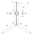
- FIG. 1 is a vertical cross-sectional view illustrating an example of a rotating electric machine according to a first embodiment.
- 1 is a cross-sectional view showing an example of a rotor of a rotating electric machine according to a first embodiment
- FIG. 2 is a partial cross-sectional view showing the state of a straight portion in a stator slot of the stator according to the first embodiment.
- FIG. 11 is a connection diagram showing a connection state between straight portions of each layer in each slot of a stator winding in a conventional example for comparison with the first embodiment.
- FIG. 4 is a connection diagram showing a connection state between straight portions of each layer in each slot of a stator winding of the stator according to the first embodiment.
- FIG. 2 is a connection diagram of a stator winding of a stator according to the first embodiment.
- FIG. 11 is a connection diagram showing a connection state between straight portions of each layer in each slot of a stator winding in a conventional example for comparison with the second embodiment.
- FIG. 11 is a connection diagram showing a connection state between straight portions of each layer in each slot of a stator winding of a stator according to a second embodiment.
- FIG. 11 is a connection diagram of a stator winding of a stator according to a second embodiment.
- FIG. 1 is a vertical cross-sectional view illustrating an example of a rotating electric machine according to a first embodiment.
- FIG. 1 is a vertical cross-sectional view showing an example of a rotating electric machine 1 having a stator 100 according to an embodiment.
- the rotating electric machine 1 comprises a rotor 10, a bearing 21, a bearing bracket 22, a frame 23, and a stator 100.
- the rotor 10 has a rotor shaft 11 extending in the direction of the rotation axis CL, a rotor core 12 attached radially outside the rotor shaft 11, permanent magnets 13 embedded in the rotor core 12, and closure plates 14 provided on both axial ends of the rotor core 12 to prevent the permanent magnets 13 from protruding.
- the rotor shaft 11 is rotatably supported by bearings 21 on both axial sides. Each bearing 21 is supported stationary by a bearing bracket 22.
- the stator 100 has a stator core 110 arranged radially outside the rotor core 12 with a gap between them, and a stator winding 120 partially housed within a stator slot 111 (Fig. 2) formed in the stator core 110 and wound around stator teeth 112 (Fig. 2).
- the stator 100 is housed within a frame 23 arranged to surround the radial outside and is supported stationary by the frame 23.
- the stator winding 120 has multiple coil segments 130 and multiple transition sections 125 that connect them.
- the coil segment 130 has two straight sections 131 that are respectively housed in two different stator slots 111, and a connection section 132 that connects these two straight sections 131 axially outside the first end 110a of the stator core 110.
- Each straight section 131 is respectively housed in the stator slot 111, and both ends of the straight section 131 protrude axially outside the first end 110a and second end 110b of the stator core 110.
- the crossover portion 125 connects the straight portions 131 of the coil segments 130 that protrude axially outward from the second end portion 110b.
- FIG. 2 is a cross-sectional view showing an example of the rotor 10 of the rotating electric machine 1 according to the first embodiment.
- the rotor 10 shown in FIG. 2 has two permanent magnets 13 housed in the rotor core 12 at each magnetic pole. Note that the rotor 10 shown in FIG. 2 is an example, and the stator 100 and rotating electric machine 1 according to this embodiment can also be applied to rotors of other types.
- FIG. 3 is a partial cross-sectional view showing the state of the straight portion 131 in the stator slot 111 of the stator 100 according to the first embodiment.
- stator slots 111 are axial through grooves spaced apart from one another in the circumferential direction and extending in the axial direction.
- the stator slots 111 are also formed so as to be adjacent to one another in the circumferential direction, thereby forming stator teeth 112.
- each stator slot 111 multiple flat conductors with rectangular cross sections, which are the straight sections 131 of the coil segments 130, are stacked radially while being electrically insulated from each other.
- the stator winding 120 is formed by the coil segments 130 and the jumper sections 125, the number N of stacked straight sections 131 in each stator slot 111 is an even number.
- the first layer conductor 131a, the second layer conductor 131b, the third layer conductor 131c, the fourth layer conductor 131d, the fifth layer conductor 131e, and the sixth layer conductor 131f are arranged in this order from the outside to the inside in the radial direction. That is, in this case, the number of layers N is 6.
- the radial thickness t0 of the first layer conductor 131a, the second layer conductor 131b, the third layer conductor 131c, and the fourth layer conductor 131d is substantially the same.
- the radial thickness t1 of the fifth layer conductor 131e and the sixth layer conductor 131f which correspond to the parallel portion 135 (FIG. 6) described below, is substantially half of t0.
- the thickness of not only the straight portion 131 but also the connection portion 132 and the transition portion 125 is half of t0.
- substantially the same means that the dimensions are the same in terms of design and match within the range of manufacturing error
- substantially one-half means that the dimensions are one-half of t0 in terms of design and one-half within the range of manufacturing error.
- manufacturing error includes errors in processing, assembly, measurement, etc.
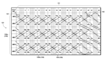
- FIG. 4 is a connection diagram showing the connection state between the straight portions 131 of each layer in each slot of the stator winding in a conventional example for comparison with the first embodiment.
- the horizontal direction of the squares shown in FIG. 4 indicates the number of the stator slot 111 as written in the top row.
- the vertical direction indicates the first to sixth layers from top to bottom.
- the symbols written in each square indicate the number of the straight portion 131 of the coil segment 130 of each layer in each stator slot 111.
- the solid lines connecting the straight portions 131 indicate the jumper portion 125.
- the dashed lines connecting the straight portions 131 indicate the connection portion 132.
- the dashed lines indicate the winding conductor 121 arranged on the axial outside of the first end 110a of the stator core 110
- the solid lines indicate the winding conductor 121 arranged on the axial outside of the second end 110b of the stator core 110.
- the straight portion 131 indicated by 1u in the first layer of the 48th slot is connected to a lead wire 141 that connects to the outside of the stator winding on the axial outside of the first end 110a of the stator core 110.
- the straight portion 131 indicated by 96u in the first layer of the 7th slot is connected to a neutral line 142 on the axial outside of the first end 110a of the stator core 110.
- the straight portion 131 indicated by 1u is represented as the straight portion 1u
- the straight portion 131 indicated by 96u is represented as the straight portion 96u.
- the U-phase coil segment 130 is shown, and the U-phase coil segment 130 is connected in series from the straight section 1u connected to the lead wire 141 to the straight section 96u connected to the neutral line 142 by the connection section 132 and the crossover section 125.
- the numbers 1u, 96u, etc. indicate the order in which the straight sections 131 are connected.
- FIG. 5 is a connection diagram showing the connection state between the straight portions 131 of each layer in each slot of the stator winding of the stator according to the first embodiment.
- the example shown in Figure 5 is for a 3-phase, 8-pole rotor with 2 slots per phase per pole, for a total of 48. Therefore, in the case of full-pitch winding, the slot spacing is 6.
- the first to third layers are connected in the same way as in the conventional example.
- the fourth to sixth layers differ from the conventional example shown in Figure 4. The differences are explained below.
- the straight portion 64u of the fourth layer of the 43rd slot is connected only to the straight portion 65u of the fifth layer of the first slot by the transition portion 125.
- the straight portion 81u of the fourth layer of the first slot is connected only to the straight portion 80u of the fifth layer of the seventh slot.
- the straight portion 32u of the fourth layer of the 43rd slot is connected to both the straight portion 33u of the fifth layer of the 48th slot and the straight portion 33u of the sixth layer of the 48th slot by the jumper portion 125. That is, the straight portion 32u of the fourth layer branches into two straight portions 33u whose radial thickness is half that of the fifth and sixth layers. Also, the straight portion 49u of the fourth layer of the first slot is connected to both the straight portion 48u of the fifth layer of the seventh slot and the straight portion 48u of the sixth layer of the 43rd slot. That is, the two straight portions 48u whose radial thickness is half that of the fifth and sixth layers are integrated with the straight portion 49u of the fourth layer.
- the first portion 135a (FIG. 6) from the straight portion 33u of the fifth layer of the 48th slot to the straight portion 48u of the sixth layer of the 43rd slot, and the second portion 135b (FIG. 6) from the straight portion 33u of the sixth layer of the 48th slot to the straight portion 48u of the fifth layer of the seventh slot are parallel portions 135 (FIG. 6) that are electrically parallel to each other.
- first portion 135a from the straight portion 33u in the fifth layer of the 48th slot to the straight portion 48u in the sixth layer of the 43rd slot is connected in a direction in which the slot number increases
- second portion 135b from the straight portion 33u in the sixth layer of the 48th slot to the straight portion 48u in the fifth layer of the 7th slot is connected in a direction in which the slot number decreases.
- the first portion 135a and the second portion 135b are connected in opposite directions.
- FIG. 6 is a connection diagram of the stator winding 120 of the stator 100 according to the first embodiment.
- One straight section 32u branches into two straight sections 33u, and then the two straight sections 48u are integrated into one straight section 49u.
- the two parallel sections, i.e., straight section 33u to straight section 48u, are arranged in the fifth and sixth layers.
- the fifth and sixth layers have parallel parts arranged and are connected to the fourth layer, but this is not limiting. It is sufficient to arrange parallel parts in two of three adjacent layers. That is, for n ⁇ 3, among the n layer, (n-1) layer, and (n-2) layer, the n layer and the (n-1) layer may be connected to the (n-2) layer as parallel parts, or the (n-1) layer and the (n-2) layer may be connected to the n layer as parallel parts.
- stator winding 120 using flat rectangular conductors stacked in a number of layers N, two adjacent layers are made into parallel portions 135 that are electrically parallel to each other, thereby achieving an electrically odd number of turns.
- the current density of each conductor can be made approximately the same.
- FIG. 7 is a connection diagram showing a connection state between straight portions of each layer in each slot of a stator winding in a conventional example for comparison with the second embodiment.
- the straight portion 131 indicated by 1u in the first layer of the first slot is connected to a lead wire 141 that connects to the outside of the stator winding on the axial outside of the first end 110a of the stator core 110. Also, the straight portion 131 indicated by 96u in the first layer of the 42nd slot is connected to a neutral line 142 on the axial outside of the first end 110a of the stator core 110.
- the U-phase coil segment 130 shown in FIG. 7 is connected in series from the straight section 1u connected to the lead wire 141 to the straight section 96u connected to the neutral line 142 by the connection section 132 and the jumper section 125.
- the transition section 125 shown by the solid line is a full-pitch winding
- the connection section 132 shown by the dashed line is not a full-pitch winding, but rather has a mixture of longer and shorter pitches.
- FIG. 8 is a connection diagram showing the connection state between the straight sections of each layer in each slot of the stator winding of the stator according to the second embodiment.
- the example shown in Figure 8 is for a 3-phase, 8-pole rotor with 2 slots per phase per pole, for a total of 48. Therefore, in the case of full-pitch winding, the slot spacing is 6.
- the first to third layers are connected in the same way as in the conventional example.
- the fourth to sixth layers differ from the conventional example shown in Figure 7. The differences are explained below.
- the straight line portion 16u in the fourth layer of the 43rd slot is connected only to the 17u in the fifth layer of the 1st slot by the jumper portion 125.
- the straight line portion 33u in the fourth layer of the 37th slot is connected only to the 32u in the fifth layer of the 43rd slot by the jumper portion 125.
- the straight line portion 60u in the fourth layer of the 18th slot is connected only to the 61u in the third layer of the 24th slot by the jumper portion 125.
- the straight line portion 85u in the fourth layer of the 12th slot is connected only to the 86u in the third layer of the 7th slot by the jumper portion 125.
- the straight portion 16u of the fourth layer of the 43rd slot is connected to both the straight portion 17u of the fifth layer of the 48th slot and the straight portion 17u of the fifth layer of the first slot by a transition portion 125.
- the straight portion 16u of the fourth layer branches into two straight portions 17u with a radial thickness that is half that of the fifth layer.
- the straight portion 25u of the fourth layer of the 37th slot is connected to both the straight portion 24u of the fifth layer of the 42nd slot and the straight portion 24u of the fifth layer of the 43rd slot by the transition portion 125.
- the two straight portions 24u of the fifth layer which have a radial thickness that is half, are integrated with the straight portion 25u of the fourth layer.
- the straight portion 56u of the fourth layer of the 18th slot is connected to both the straight portion 57u of the fifth layer of the 24th slot and the straight portion 57u of the fifth layer of the 25th slot by a transition portion 125.
- the straight portion 56u of the fourth layer branches into two straight portions 57u with a radial thickness that is half that of the fifth layer.
- the straight portion 65u of the fourth layer of the 12th slot is connected to both the straight portion 64u of the fifth layer of the 18th slot and the straight portion 64u of the fifth layer of the 19th slot by the transition portion 125.
- the two straight portions 64u of the fifth layer which have a radial thickness that is half, are integrated with the straight portion 65u of the fourth layer.
- the first portion 136a (FIG. 9) from the straight portion 17u of the fifth layer of the 48th slot to the straight portion 24u of the fifth layer of the 42nd slot, and the second portion 136b (FIG. 9) from the straight portion 17u of the fifth layer of the 1st slot to the straight portion 24u of the fifth layer of the 43rd slot are parallel portions 136 (FIG. 9) that are electrically parallel to each other.
- the first portion 137a (FIG. 9) from the straight portion 57u of the fifth layer of the 24th slot to the straight portion 64u of the fifth layer of the 18th slot, and the second portion 137b (FIG. 9) from the straight portion 57u of the fifth layer of the 25th slot to the straight portion 64u of the fifth layer of the 19th slot are parallel portions 137 (FIG. 9) that are electrically parallel to each other.
- first portion 136a and the second portion 136b are connected in the opposite directions.
- first portion 137a and the second portion 137b are also connected in the opposite directions.
- FIG. 9 is a connection diagram of the stator windings of the stator according to the second embodiment.
- one straight portion 16u branches into two straight portions 17u, and then the two straight portions 24u are integrated into one straight portion 25u.
- one straight portion 56u branches into two straight portions 57u, and then the two straight portions 64u are integrated into one straight portion 65u.
- the straight portions in the two parallel portions 136 and 137 are arranged in the fifth and sixth layers.
- parallel portions are arranged on the fifth and sixth layers and connected to the fourth layer, but this is not limiting.
- parallel portions may be arranged on two adjacent layers out of three adjacent layers.
- stator winding 120 using flat rectangular conductors stacked in a number of layers N, two adjacent layers are made into parallel portions 135 that are electrically parallel to each other, so that an odd number of turns can be achieved electrically, as in the first embodiment.
- the current density of each conductor can be made approximately the same, and further, as illustrated in this embodiment, by making the parallel portion 135, in which the thickness t1 of the rectangular conductor is half the thickness t0 of the rectangular conductor of the other layers, the innermost layer and the layer outside it, it is possible to reduce eddy current loss due to magnetic flux linking the layer conductors, which is the same as the first embodiment.
Landscapes
- Engineering & Computer Science (AREA)
- Power Engineering (AREA)
- Windings For Motors And Generators (AREA)
Priority Applications (2)
| Application Number | Priority Date | Filing Date | Title |
|---|---|---|---|
| JP2023550639A JPWO2024185063A1 (en, 2012) | 2023-03-08 | 2023-03-08 | |
| PCT/JP2023/008761 WO2024185063A1 (ja) | 2023-03-08 | 2023-03-08 | 固定子および回転電機 |
Applications Claiming Priority (1)
| Application Number | Priority Date | Filing Date | Title |
|---|---|---|---|
| PCT/JP2023/008761 WO2024185063A1 (ja) | 2023-03-08 | 2023-03-08 | 固定子および回転電機 |
Publications (1)
| Publication Number | Publication Date |
|---|---|
| WO2024185063A1 true WO2024185063A1 (ja) | 2024-09-12 |
Family
ID=92674325
Family Applications (1)
| Application Number | Title | Priority Date | Filing Date |
|---|---|---|---|
| PCT/JP2023/008761 WO2024185063A1 (ja) | 2023-03-08 | 2023-03-08 | 固定子および回転電機 |
Country Status (2)
| Country | Link |
|---|---|
| JP (1) | JPWO2024185063A1 (en, 2012) |
| WO (1) | WO2024185063A1 (en, 2012) |
Citations (10)
| Publication number | Priority date | Publication date | Assignee | Title |
|---|---|---|---|---|
| US3949254A (en) * | 1974-02-25 | 1976-04-06 | Westinghouse Electric Corporation | Winding for dynamoelectric machine |
| JP2000092766A (ja) * | 1998-09-07 | 2000-03-31 | Denso Corp | 車両用交流発電機の固定子 |
| JP2002058189A (ja) * | 2000-08-10 | 2002-02-22 | Mitsubishi Electric Corp | 回転電機 |
| JP2005312278A (ja) * | 2004-04-26 | 2005-11-04 | Denso Corp | 回転電機の集中巻き型ステータコイル |
| JP2005312277A (ja) * | 2004-04-26 | 2005-11-04 | Denso Corp | 回転電機の集中巻き型ステータコイル |
| JP2016012981A (ja) * | 2014-06-27 | 2016-01-21 | 株式会社デンソー | 回転電機の固定子 |
| JP2017093097A (ja) * | 2015-11-06 | 2017-05-25 | 株式会社デンソー | 回転電機 |
| JP2022006576A (ja) * | 2020-06-24 | 2022-01-13 | 株式会社Subaru | ステータ |
| JP2022074588A (ja) * | 2020-11-04 | 2022-05-18 | 株式会社デンソー | 回転電機 |
| JP7186927B2 (ja) * | 2020-06-09 | 2022-12-09 | 株式会社東芝 | 回転電機の固定子 |
Family Cites Families (1)
| Publication number | Priority date | Publication date | Assignee | Title |
|---|---|---|---|---|
| JP5532622B2 (ja) * | 2009-02-20 | 2014-06-25 | パナソニック株式会社 | モータ |
-
2023
- 2023-03-08 WO PCT/JP2023/008761 patent/WO2024185063A1/ja active Application Filing
- 2023-03-08 JP JP2023550639A patent/JPWO2024185063A1/ja active Pending
Patent Citations (10)
| Publication number | Priority date | Publication date | Assignee | Title |
|---|---|---|---|---|
| US3949254A (en) * | 1974-02-25 | 1976-04-06 | Westinghouse Electric Corporation | Winding for dynamoelectric machine |
| JP2000092766A (ja) * | 1998-09-07 | 2000-03-31 | Denso Corp | 車両用交流発電機の固定子 |
| JP2002058189A (ja) * | 2000-08-10 | 2002-02-22 | Mitsubishi Electric Corp | 回転電機 |
| JP2005312278A (ja) * | 2004-04-26 | 2005-11-04 | Denso Corp | 回転電機の集中巻き型ステータコイル |
| JP2005312277A (ja) * | 2004-04-26 | 2005-11-04 | Denso Corp | 回転電機の集中巻き型ステータコイル |
| JP2016012981A (ja) * | 2014-06-27 | 2016-01-21 | 株式会社デンソー | 回転電機の固定子 |
| JP2017093097A (ja) * | 2015-11-06 | 2017-05-25 | 株式会社デンソー | 回転電機 |
| JP7186927B2 (ja) * | 2020-06-09 | 2022-12-09 | 株式会社東芝 | 回転電機の固定子 |
| JP2022006576A (ja) * | 2020-06-24 | 2022-01-13 | 株式会社Subaru | ステータ |
| JP2022074588A (ja) * | 2020-11-04 | 2022-05-18 | 株式会社デンソー | 回転電機 |
Also Published As
| Publication number | Publication date |
|---|---|
| JPWO2024185063A1 (en, 2012) | 2024-09-12 |
Similar Documents
| Publication | Publication Date | Title |
|---|---|---|
| US7859164B2 (en) | Armature laminations | |
| US10666104B2 (en) | Rotating electrical machine | |
| US5057731A (en) | Simplified spindle motor for disc drive | |
| JP6539141B2 (ja) | 回転電機の固定子及び回転電機 | |
| JP2009509488A (ja) | 電気駆動機械 | |
| JP6132156B2 (ja) | 回転電機 | |
| CN112583168B (zh) | 一种电机定子绕组、定子及电机 | |
| WO2021240989A1 (ja) | 回転電機用ステータ | |
| WO2024185063A1 (ja) | 固定子および回転電機 | |
| JP2009065750A (ja) | 回転機 | |
| JP2017184475A (ja) | モータ装置、およびモータ装置の製造方法 | |
| JP7721981B2 (ja) | 回転電機用ステータ | |
| CN214543854U (zh) | 一种电机定子绕组、定子及电机 | |
| WO2019064373A1 (ja) | 電動機及び電動機の製造方法 | |
| CN115347691A (zh) | 一种电机定子及电机 | |
| JP3494729B2 (ja) | 三相電機子巻線 | |
| CN112467898A (zh) | 一种电机定子及电机 | |
| JP6498775B2 (ja) | 固定子および回転電機 | |
| JP7661621B1 (ja) | 回転電機の固定子巻線及び回転電機 | |
| CN219247551U (zh) | 定子组件及电机 | |
| CN112332564A (zh) | 一种电机定子及电机 | |
| JP2025089650A (ja) | 固定子および回転電機 | |
| CN216819543U (zh) | 一种定子及电机 | |
| JP7552907B2 (ja) | 回転電機用ステータ及び回転電機用ステータの製造方法 | |
| CN215772693U (zh) | 一种电机定子及电机 |
Legal Events
| Date | Code | Title | Description |
|---|---|---|---|
| WWE | Wipo information: entry into national phase |
Ref document number: 2023550639 Country of ref document: JP |
|
| 121 | Ep: the epo has been informed by wipo that ep was designated in this application |
Ref document number: 23926276 Country of ref document: EP Kind code of ref document: A1 |