WO2024185025A1 - ロータ用スリーブ、ロータおよびモータ - Google Patents
ロータ用スリーブ、ロータおよびモータ Download PDFInfo
- Publication number
- WO2024185025A1 WO2024185025A1 PCT/JP2023/008444 JP2023008444W WO2024185025A1 WO 2024185025 A1 WO2024185025 A1 WO 2024185025A1 JP 2023008444 W JP2023008444 W JP 2023008444W WO 2024185025 A1 WO2024185025 A1 WO 2024185025A1
- Authority
- WO
- WIPO (PCT)
- Prior art keywords
- hole portion
- fitted
- small diameter
- hole
- diameter
- Prior art date
- Legal status (The legal status is an assumption and is not a legal conclusion. Google has not performed a legal analysis and makes no representation as to the accuracy of the status listed.)
- Ceased
Links
Images


Classifications
-
- H—ELECTRICITY
- H02—GENERATION; CONVERSION OR DISTRIBUTION OF ELECTRIC POWER
- H02K—DYNAMO-ELECTRIC MACHINES
- H02K1/00—Details of the magnetic circuit
- H02K1/06—Details of the magnetic circuit characterised by the shape, form or construction
- H02K1/22—Rotating parts of the magnetic circuit
- H02K1/28—Means for mounting or fastening rotating magnetic parts on to, or to, the rotor structures
- H02K1/30—Means for mounting or fastening rotating magnetic parts on to, or to, the rotor structures using intermediate parts, e.g. spiders
-
- H—ELECTRICITY
- H02—GENERATION; CONVERSION OR DISTRIBUTION OF ELECTRIC POWER
- H02K—DYNAMO-ELECTRIC MACHINES
- H02K15/00—Processes or apparatus specially adapted for manufacturing, assembling, maintaining or repairing of dynamo-electric machines
- H02K15/02—Processes or apparatus specially adapted for manufacturing, assembling, maintaining or repairing of dynamo-electric machines of stator or rotor bodies
- H02K15/028—Fastening stator or rotor bodies to casings, supports, shafts or hubs
-
- H—ELECTRICITY
- H02—GENERATION; CONVERSION OR DISTRIBUTION OF ELECTRIC POWER
- H02K—DYNAMO-ELECTRIC MACHINES
- H02K15/00—Processes or apparatus specially adapted for manufacturing, assembling, maintaining or repairing of dynamo-electric machines
- H02K15/50—Disassembling, repairing or modifying dynamo-electric machines
-
- H—ELECTRICITY
- H02—GENERATION; CONVERSION OR DISTRIBUTION OF ELECTRIC POWER
- H02K—DYNAMO-ELECTRIC MACHINES
- H02K7/00—Arrangements for handling mechanical energy structurally associated with dynamo-electric machines, e.g. structural association with mechanical driving motors or auxiliary dynamo-electric machines
- H02K7/003—Couplings; Details of shafts
Definitions
- This disclosure relates to a rotor sleeve, a rotor, and a motor.
- a rotor that includes a sleeve that is fitted to the outer circumferential surface of the main shaft while forming a sealed gap, and a cylindrical iron core that is fitted to the outer circumferential surface of the sleeve (see, for example, Patent Document 1).
- Clamp discs are also fitted to the outer circumferential surface of the sleeve on both axially outer sides of the iron core.
- the clamp disc is made of a different material or is processed to a different precision than the core, so that the portion of the sleeve that corresponds to the clamp disc may deform radially inward relative to the portion that corresponds to the core. Furthermore, when the sleeve is fitted to the main shaft in this state, the fit between the sleeve and the main shaft becomes stronger than necessary, and a larger hydraulic pressure is required when disassembling the rotor, which reduces workability. Therefore, in a rotor having a sleeve with an iron core and a member other than the iron core fitted onto its outer peripheral surface, it is desirable to improve the ease of removing the sleeve from the main shaft.
- One aspect of the present disclosure is a method for manufacturing a drive shaft having a small diameter shaft portion and a large diameter shaft portion aligned in the axial direction and having different outer diameters, the drive shaft having a small diameter shaft portion and a large diameter shaft portion aligned in the axial direction ... and an intermediate hole portion that is arranged between the main shaft and the through hole portion and through which hydraulic pressure is supplied between the main shaft and the through hole portion.
- the inner diameter of the through hole located radially inward of the second fitting outer surface on the small diameter hole portion side is larger than the inner diameter of the small diameter hole portion located radially inward of the first fitting outer surface, and the inner diameter of the through hole located radially inward of the second fitting outer surface on the large diameter hole portion side is larger than the inner diameter of the large diameter hole portion located radially inward of the first fitting outer surface.
- FIG. 1 is a longitudinal sectional view showing a rotor according to a first embodiment of the present disclosure.
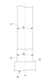
- FIG. 2 is a side view showing a part of a main shaft constituting the rotor of FIG. 1 .
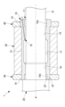
- FIG. 2 is a longitudinal cross-sectional view showing a sleeve according to the first embodiment of the present disclosure.
- FIG. 4 is a vertical cross-sectional view showing a state in which an iron core and a side ring are fitted into the sleeve of FIG. 3 .
- FIG. 2 is a longitudinal sectional view showing a portion of a first modified example of the rotor of FIG. 1 .
- FIG. 2 is a vertical cross-sectional view showing a second modified example of the rotor of FIG. 1 .
- the rotor 1 is, for example, a rotor for a built-in motor in which a stator is built into an industrial machine.
- the rotor 1 includes a main shaft 20 and a cylindrical sleeve (rotor sleeve) 10 having a through hole 11 into which the main shaft 20 fits.
- the rotor 1 also includes an iron core 30 and two side rings 40 fixed to the outer circumferential surface of the sleeve 10.
- the main shaft 20 includes a small diameter shaft portion 21 and a large diameter shaft portion 22 arranged side by side in the direction along the axis A.
- the main shaft 20 also includes an abutment surface 23 at one end of the sleeve 10 that abuts in the direction along the axis A.
- the small diameter shaft portion 21 and the large diameter shaft portion 22 each have a smooth cylindrical outer surface, and the outer diameter dimension D1 of the small diameter shaft portion 21 is smaller than the outer diameter dimension D2 of the large diameter shaft portion 22.
- a step is formed between the small diameter shaft portion 21 and the large diameter shaft portion 22, the height of which corresponds to the difference between the outer diameter dimensions ((D2-D1)/2).
- the sleeve 10 has an outer peripheral surface (first mating outer surface) 13 into which the iron core 30 (described later) is mated at a central position in the direction of the axis A.
- the sleeve 10 also has a pair of outer peripheral surfaces (second mating outer surfaces) 14 adjacent to both outer sides in the direction of the axis A of the outer peripheral surface 13, into which side rings 40 (described later) are mated.
- the core 30 is formed into a cylindrical shape by stacking a number of members, each of which is made by punching a thin sheet of a magnetic material such as an electromagnetic steel sheet into an annular shape, in the thickness direction.
- the inner peripheral surface of the core 30 is fitted into the outer peripheral surface 13 of the sleeve 10, and is in close contact with it all around.
- Each side ring 40 is an annular member having an outer diameter larger than that of the iron core 30, and is fitted to the corresponding outer peripheral surface 14, just like the iron core 30. That is, the pair of side rings 40 are arranged on both outsides of the iron core 30 in the direction of the axis A, and protect the iron core 30 from contacting the inner surface of the stator when the rotor 1 is inserted into the stator.
- the side ring 40 also has multiple screw holes (not shown) for fixing a mass for balancing the rotor 1.
- the side ring 40 is made of a non-magnetic material to reduce leakage flux in the direction of axis A of the magnetic flux passing through the iron core 30.
- the linear expansion coefficient of a non-magnetic material is greater than that of the magnetic material that constitutes the iron core 30, so the side ring 40 is fitted to the sleeve 10 with a larger interference than that of the iron core 30.
- the iron core 30 and the side ring 40 when fitting the iron core 30 and the side ring 40 to the outer peripheral surfaces 13, 14 of the sleeve 10, the iron core 30 and the side ring 40 are heated to increase their inner diameters, and then fitted to the sleeve 10. The iron core 30 and the side ring 40 are then cooled to room temperature, causing the inner diameter to shrink, and are then fixed in close contact with the outer peripheral surfaces 13, 14 of the sleeve 10, a process known as shrink fitting.
- Shrink fitting is also performed when fitting the main shaft 20 into the through hole 11 of the sleeve 10 to which the iron core 30 and side ring 40 have been shrink fitted in this manner.
- the interference between the iron core 30 and the side ring 40 and the sleeve 10 is the same, there is a risk that the side ring 40, which has a large linear expansion coefficient, will loosen and fall off due to heating during shrink fitting. Therefore, by setting the interference of the side ring 40 to be greater than the interference of the iron core 30, the side ring 40 is prevented from falling off during shrink fitting.
- the through hole 11 of the sleeve 10 has a small diameter hole portion 15 at one end in the axial A direction into which the small diameter shaft portion 21 of the main shaft 20 is fitted, and a large diameter hole portion 16 at the other end into which the large diameter shaft portion 22 of the main shaft 20 is fitted.
- the through hole 11 also has an intermediate hole portion 17 that is disposed between the small diameter hole portion 15 and the large diameter hole portion 16 in the axial A direction and has an inner diameter larger than that of the large diameter hole portion 16.
- the through hole 11 has an end hole portion 15e located radially inward of one outer peripheral surface 14 on the outside of the small diameter hole portion 15 in the axial A direction.
- the through hole 11 has an end hole portion 16e located radially inward of the other outer peripheral surface 14 on the outside of the large diameter hole portion 16 in the axial A direction.
- the sleeve 10 is set to the following dimensions at room temperature before the core 30 and side ring 40 are fitted. That is, the inner diameter dimensions d1 and d2 of the small diameter hole portion 15 and the large diameter hole portion 16 are set to be smaller than the outer diameter dimensions D1 and D2 of the small diameter shaft portion 21 and the large diameter shaft portion 22 of the main shaft 20, respectively, by the amount of tightening.
- the inner diameter dimension d1' of the end hole portion 15e is set to be larger than the outer diameter dimension D1 of the small diameter shaft portion 21 of the main shaft 20, and the inner diameter dimension d2' of the end hole portion 16e is set to be larger than the outer diameter dimension D2 of the large diameter shaft portion 22 of the main shaft 20.
- the inner diameter dimensions d1', d2' are set so that the dimensional differences (d1'-D1) and (d2'-D2), respectively, are equal to or larger than the amount of contraction of the inner diameter dimensions d1', d2' due to shrink fitting of the side ring 40 described below.
- the intermediate hole portion 17 defines a sealed cylindrical space between the outer circumferential surface of the main shaft 20.
- a hydraulic supply hole 18 for supplying hydraulic pressure from outside the sleeve 10 opens into the space defined by the intermediate hole portion 17.
- the iron core 30 and the side rings 40 are fitted by shrink fitting to the outer circumferential surface 13 and the pair of outer circumferential surfaces 14 of the sleeve 10, respectively. This forms a unit in which the iron core 30 and the side rings 40 are integrally attached to the sleeve 10.
- the sleeve 10 is cooled to room temperature, and a stress corresponding to the size of the interference of each component acts on the sleeve 10.
- a greater stress acts on the parts of the sleeve 10 that correspond to each side ring 40, which is fitted with a larger interference, than on the parts that correspond to the core 30.
- the end hole portions 15e, 16e of the through hole 11 of the sleeve 10 are slightly deformed radially inward, as shown in FIG. 4, i.e., the inner diameter dimensions d1', d2' are contracted.
- the unit is heated and the spindle 20 is inserted into the through hole 11 of the sleeve 10 by shrink fitting from the large diameter hole portion 16 side toward the small diameter hole portion 15 side. Then, the abutment surface 23 of the spindle 20 is abutted against the end surface of the end hole portion 16e of the sleeve 10, thereby positioning the spindle 20 and the sleeve 10 in the direction of the axis A.
- the unit is cooled to room temperature, whereby the small diameter shaft portion 21 and the large diameter shaft portion 22 of the main shaft 20 are fitted closely into the small diameter hole portion 15 and the large diameter hole portion 16 of the sleeve 10, respectively, and the rotor 1 is assembled.
- the inner diameters of the end holes 15e, 16e of the sleeve 10 before the iron core 30 and the side ring 40 are fitted are set to be larger than the adjacent small diameter hole portion 15 and large diameter hole portion 16, respectively. Therefore, even if the inner diameters of the end holes 15e, 16e are contracted by fitting the side ring 40, it is possible to ensure that the inner diameter of the end hole portion 15e is equal to or larger than the inner diameter of the small diameter hole portion 15, and the inner diameter of the end hole portion 16e is equal to or larger than the inner diameter of the large diameter hole portion 16.
- the sleeve 10 may have weak parts at the boundaries between the part corresponding to the iron core 30 and the parts corresponding to each side ring 40, where the cross-sectional area is locally reduced, as shown in FIG. 5.
- the fragile portions are formed by circumferential grooves 19o, 19i provided at the boundary between the outer peripheral surface 13 and the pair of outer peripheral surfaces 14, the boundary between the small diameter hole portion 15 and the end hole portion 15e, and the boundary between the large diameter hole portion 16 and the end hole portion 16e.
- the circumferential grooves 19o, 19i may be omitted, or the circumferential grooves 19o, 19i may be composed of multiple grooves arranged intermittently in the circumferential direction.
- the fragile portion may be formed by a shape other than a groove, as long as it locally reduces the cross-sectional area of the boundary between the portion of the sleeve 10 corresponding to the iron core 30 and the portion corresponding to each side ring 40.
- the side ring 40 is made of a non-magnetic material, but the present invention is not limited to this.
- the side ring 40 may be made of a magnetic material, similar to the iron core 30.
- the interference between the two with respect to the sleeve 10 can be set to the same value. In other words, it is possible to prevent radially inward deformation of the end holes 15e, 16e due to the difference in interference between the iron core 30 and the side ring 40.
- the end holes 15e, 16e may be deformed radially inward.
- the roundness of the inner peripheral surface of the side ring 40 is poorer than that of the inner peripheral surface of the core 30, the end holes 15e, 16e of the through hole 11 will be deformed radially inward. Even in such a case, the same effect as above can be obtained by applying the sleeve 10 or rotor 1 according to this embodiment.
- the small diameter hole portion 15 and the large diameter hole portion 16 of the sleeve 10 are fixed in close contact with the small diameter shaft portion 21 and the large diameter shaft portion 22, respectively, over the entire circumference.
- the small diameter hole portion 15 and the large diameter hole portion 16 may be fixed partially to the small diameter shaft portion 21 and the large diameter shaft portion 22, respectively.
- a plurality of linear grooves extending in the direction of axis A may be arranged on the inner circumferential surfaces of small diameter hole portion 15 and large diameter hole portion 16 at equal intervals in the circumferential direction.
- the width dimension of the straight groove, etc. it is possible to optimize the fitting area between the small diameter hole portion 15 and the small diameter shaft portion 21 and the fitting area between the large diameter hole portion 16 and the large diameter shaft portion 22. This makes it easier to remove the sleeve 10 from the main shaft 20.
- a step portion 24 may be provided adjacent to the outside in the direction of the axis A of the small diameter shaft portion 21 of the main shaft 20.
- the step 24 has an outer diameter D3 that is smaller than the outer diameter D1 of the small diameter shaft portion 21. Therefore, a step of a height ((D1-D3)/2) corresponding to the difference in the outer diameter dimensions is formed between the small diameter shaft portion 21 and the step 24. Furthermore, when the rotor 1 is assembled, the step 24 is positioned radially inward of the portion of the small diameter hole portion 15 that corresponds to the side ring 40.
- a gap of a size corresponding to the step ((D1-D3)/2) between the small diameter shaft portion 21 and the step portion 24 is formed between the inner surface of the portion of the small diameter hole portion 15 corresponding to the side ring 40 and the outer surface of the step portion 24.
- the deformation can be absorbed by the amount of the leeway formed by the step portion 24.
- the dimensional differences (d1'-D1) and (d2'-D2) of the inner diameter dimensions d1' and d2' of the end holes 15e and 16e are set to be equal to or greater than the amount of shrinkage of the inner diameter dimensions d1' and d2' due to shrink fitting of the side ring 40.
- the dimensional differences (d1'-D1) and (d2'-D2) may be smaller than the amount of shrinkage of the inner diameter dimensions d1' and d2' due to shrink fitting of the side ring 40.
- the sleeve 10 and the main shaft 20 are in close contact with each other even at the end holes 15e and 16e, but the fixing force between the sleeve 10 and the main shaft 20 is lower than when the end holes 15e and 16e are not provided. This improves the ease of assembly and disassembly of the rotor 1.
- the end holes in the drawings are exaggerated, and in reality, the amount of shrinkage of the inner diameter dimensions d1', d2' of the end holes 15e, 16e due to shrink fitting may be so minute that it does not appear in the drawings. Therefore, the small diameter hole portion 15 and the large diameter hole portion 16 may be a tight fit, and the end holes 15e, 16e may be a clearance fit, with the size relationship being specified within the range of the dimensional tolerance for the same nominal dimensions.
- the drive shaft has a through hole for fitting a main shaft having a small diameter shaft portion and a large diameter shaft portion aligned in an axial direction and different outer diameter dimensions, a first fitting outer surface into which an inner surface of a cylindrical iron core can be fitted, and second fitting outer surfaces arranged adjacent to both outer sides of the first fitting outer surface in the axial direction and into which inner surfaces of a pair of cylindrical side rings can be respectively fitted, and the through hole has a small diameter hole portion into which the small diameter shaft portion is fitted, a large diameter hole portion into which the large diameter shaft portion is fitted, and a small diameter hole portion and a large diameter hole portion in the axial direction.
- Appendix 2 A rotor sleeve as described in Appendix 1, which has a weak portion with a locally reduced cross-sectional area on at least one of the boundaries between the first mating outer surface and each of the second mating outer surfaces and the inner surface of the through hole corresponding to said boundaries.
- Appendix 3 3. The rotor sleeve according to claim 2, wherein the weakened portion is a groove extending in a circumferential direction on at least one of the boundary and an inner surface of the through hole corresponding to the boundary.
- Appendix 4 4.
- a rotor comprising: the rotor sleeve according to claim 1; the core shrink-fitted to the first outer mating surface; and a pair of side rings shrink-fitted to the second outer mating surface.
- Appendix 5 5.
- Appendix 6 6.
- a motor comprising the rotor according to any one of Supplementary Note 4 to Supplementary Note 6.
Landscapes
- Engineering & Computer Science (AREA)
- Power Engineering (AREA)
- Manufacturing & Machinery (AREA)
- Iron Core Of Rotating Electric Machines (AREA)
Priority Applications (5)
| Application Number | Priority Date | Filing Date | Title |
|---|---|---|---|
| CN202380094776.1A CN120752832A (zh) | 2023-03-07 | 2023-03-07 | 转子用套筒、转子以及马达 |
| JP2025504956A JPWO2024185025A1 (https=) | 2023-03-07 | 2023-03-07 | |
| DE112023005143.7T DE112023005143T5 (de) | 2023-03-07 | 2023-03-07 | Läuferhülse, läufer und motor |
| PCT/JP2023/008444 WO2024185025A1 (ja) | 2023-03-07 | 2023-03-07 | ロータ用スリーブ、ロータおよびモータ |
| TW113106033A TW202437646A (zh) | 2023-03-07 | 2024-02-20 | 轉子用套筒、轉子以及馬達 |
Applications Claiming Priority (1)
| Application Number | Priority Date | Filing Date | Title |
|---|---|---|---|
| PCT/JP2023/008444 WO2024185025A1 (ja) | 2023-03-07 | 2023-03-07 | ロータ用スリーブ、ロータおよびモータ |
Publications (1)
| Publication Number | Publication Date |
|---|---|
| WO2024185025A1 true WO2024185025A1 (ja) | 2024-09-12 |
Family
ID=92674238
Family Applications (1)
| Application Number | Title | Priority Date | Filing Date |
|---|---|---|---|
| PCT/JP2023/008444 Ceased WO2024185025A1 (ja) | 2023-03-07 | 2023-03-07 | ロータ用スリーブ、ロータおよびモータ |
Country Status (5)
| Country | Link |
|---|---|
| JP (1) | JPWO2024185025A1 (https=) |
| CN (1) | CN120752832A (https=) |
| DE (1) | DE112023005143T5 (https=) |
| TW (1) | TW202437646A (https=) |
| WO (1) | WO2024185025A1 (https=) |
Cited By (1)
| Publication number | Priority date | Publication date | Assignee | Title |
|---|---|---|---|---|
| CN119519201A (zh) * | 2024-10-25 | 2025-02-25 | 珠海格力电器股份有限公司 | 一种电机及机床 |
Citations (4)
| Publication number | Priority date | Publication date | Assignee | Title |
|---|---|---|---|---|
| JPH1199403A (ja) * | 1997-09-26 | 1999-04-13 | Toyoda Mach Works Ltd | 主軸装置 |
| JP2013009528A (ja) * | 2011-06-24 | 2013-01-10 | Fanuc Ltd | 回転軸にスリーブを高精度に取り付け可能な電動機 |
| CN112737180A (zh) * | 2021-01-07 | 2021-04-30 | 深圳市爱贝科精密工业股份有限公司 | 一种便于拆卸和安装的转子机构 |
| JP7219375B1 (ja) * | 2022-07-19 | 2023-02-07 | ファナック株式会社 | ロータ用スリーブおよびロータ |
-
2023
- 2023-03-07 DE DE112023005143.7T patent/DE112023005143T5/de active Pending
- 2023-03-07 JP JP2025504956A patent/JPWO2024185025A1/ja active Pending
- 2023-03-07 CN CN202380094776.1A patent/CN120752832A/zh active Pending
- 2023-03-07 WO PCT/JP2023/008444 patent/WO2024185025A1/ja not_active Ceased
-
2024
- 2024-02-20 TW TW113106033A patent/TW202437646A/zh unknown
Patent Citations (4)
| Publication number | Priority date | Publication date | Assignee | Title |
|---|---|---|---|---|
| JPH1199403A (ja) * | 1997-09-26 | 1999-04-13 | Toyoda Mach Works Ltd | 主軸装置 |
| JP2013009528A (ja) * | 2011-06-24 | 2013-01-10 | Fanuc Ltd | 回転軸にスリーブを高精度に取り付け可能な電動機 |
| CN112737180A (zh) * | 2021-01-07 | 2021-04-30 | 深圳市爱贝科精密工业股份有限公司 | 一种便于拆卸和安装的转子机构 |
| JP7219375B1 (ja) * | 2022-07-19 | 2023-02-07 | ファナック株式会社 | ロータ用スリーブおよびロータ |
Cited By (1)
| Publication number | Priority date | Publication date | Assignee | Title |
|---|---|---|---|---|
| CN119519201A (zh) * | 2024-10-25 | 2025-02-25 | 珠海格力电器股份有限公司 | 一种电机及机床 |
Also Published As
| Publication number | Publication date |
|---|---|
| CN120752832A (zh) | 2025-10-03 |
| TW202437646A (zh) | 2024-09-16 |
| DE112023005143T5 (de) | 2025-10-02 |
| JPWO2024185025A1 (https=) | 2024-09-12 |
Similar Documents
| Publication | Publication Date | Title |
|---|---|---|
| JP5139562B2 (ja) | 回転軸にスリーブを高精度に取り付け可能な電動機 | |
| JP5718391B2 (ja) | 回転電機 | |
| KR100950829B1 (ko) | 회전 전기기계의 회전자, 및 그 제조 방법 | |
| AU2017225044B2 (en) | Rotary electric rotor and method of manufacturing rotary electric rotor | |
| TW202406268A (zh) | 轉子套筒及轉子 | |
| EP3018802B1 (en) | Method for producing a rotor | |
| WO2010001776A1 (ja) | 永久磁石式回転機の回転子構造 | |
| JP2016201896A (ja) | ロータ及びその製造方法 | |
| JP6264339B2 (ja) | 積層ロータの焼嵌方法 | |
| WO2024185025A1 (ja) | ロータ用スリーブ、ロータおよびモータ | |
| EP2639403B1 (en) | Shaft Assembly for a Gas Turbine Engine | |
| JP5777529B2 (ja) | インペラ及びこれを備えたロータ並びにインペラの製造方法 | |
| CN110337549B (zh) | 分解器轴承装置 | |
| JP3309707B2 (ja) | 軸受構造体 | |
| JP4723595B2 (ja) | ガスタービン用永久磁石発電機ロータ、その製造方法及びガスタービン | |
| WO2013164880A1 (ja) | 回転電機の回転子構造 | |
| US20230283124A1 (en) | Rotor for a rotating electric machine | |
| JP6351915B1 (ja) | 回転子部材及び回転電機 | |
| US20250149943A1 (en) | Rotor for an electric machine | |
| US20240388147A1 (en) | Stator assembly | |
| US12395050B2 (en) | Method for manufacturing a rotor for an electrical machine with an axial fixing of a laminated core by means of friction welding, as well as a rotor | |
| WO2024084548A1 (ja) | ロータ用スリーブおよびロータ | |
| CN116569447A (zh) | 轴向固定电机的轴部件 | |
| JP2006311667A (ja) | 電動機回転子 |
Legal Events
| Date | Code | Title | Description |
|---|---|---|---|
| 121 | Ep: the epo has been informed by wipo that ep was designated in this application |
Ref document number: 23926239 Country of ref document: EP Kind code of ref document: A1 |
|
| WWE | Wipo information: entry into national phase |
Ref document number: 2025504956 Country of ref document: JP |
|
| WWE | Wipo information: entry into national phase |
Ref document number: 112023005143 Country of ref document: DE |
|
| WWE | Wipo information: entry into national phase |
Ref document number: 202380094776.1 Country of ref document: CN |
|
| WWP | Wipo information: published in national office |
Ref document number: 112023005143 Country of ref document: DE |
|
| WWP | Wipo information: published in national office |
Ref document number: 202380094776.1 Country of ref document: CN |
|
| 122 | Ep: pct application non-entry in european phase |
Ref document number: 23926239 Country of ref document: EP Kind code of ref document: A1 |