EP2639403B1 - Shaft Assembly for a Gas Turbine Engine - Google Patents
Shaft Assembly for a Gas Turbine Engine Download PDFInfo
- Publication number
- EP2639403B1 EP2639403B1 EP12187480.4A EP12187480A EP2639403B1 EP 2639403 B1 EP2639403 B1 EP 2639403B1 EP 12187480 A EP12187480 A EP 12187480A EP 2639403 B1 EP2639403 B1 EP 2639403B1
- Authority
- EP
- European Patent Office
- Prior art keywords
- nut
- segment
- nut segment
- shaft assembly
- annular
- Prior art date
- Legal status (The legal status is an assumption and is not a legal conclusion. Google has not performed a legal analysis and makes no representation as to the accuracy of the status listed.)
- Active
Links
- 230000007423 decrease Effects 0.000 claims description 3
- 238000007789 sealing Methods 0.000 description 14
- 239000012530 fluid Substances 0.000 description 3
- 230000000712 assembly Effects 0.000 description 2
- 238000000429 assembly Methods 0.000 description 2
- 230000001154 acute effect Effects 0.000 description 1
- 238000013016 damping Methods 0.000 description 1
- 230000000694 effects Effects 0.000 description 1
Images


Classifications
-
- F—MECHANICAL ENGINEERING; LIGHTING; HEATING; WEAPONS; BLASTING
- F01—MACHINES OR ENGINES IN GENERAL; ENGINE PLANTS IN GENERAL; STEAM ENGINES
- F01D—NON-POSITIVE DISPLACEMENT MACHINES OR ENGINES, e.g. STEAM TURBINES
- F01D5/00—Blades; Blade-carrying members; Heating, heat-insulating, cooling or antivibration means on the blades or the members
- F01D5/02—Blade-carrying members, e.g. rotors
- F01D5/025—Fixing blade carrying members on shafts
-
- F—MECHANICAL ENGINEERING; LIGHTING; HEATING; WEAPONS; BLASTING
- F01—MACHINES OR ENGINES IN GENERAL; ENGINE PLANTS IN GENERAL; STEAM ENGINES
- F01D—NON-POSITIVE DISPLACEMENT MACHINES OR ENGINES, e.g. STEAM TURBINES
- F01D5/00—Blades; Blade-carrying members; Heating, heat-insulating, cooling or antivibration means on the blades or the members
- F01D5/02—Blade-carrying members, e.g. rotors
- F01D5/06—Rotors for more than one axial stage, e.g. of drum or multiple disc type; Details thereof, e.g. shafts, shaft connections
- F01D5/066—Connecting means for joining rotor-discs or rotor-elements together, e.g. by a central bolt, by clamps
-
- F—MECHANICAL ENGINEERING; LIGHTING; HEATING; WEAPONS; BLASTING
- F05—INDEXING SCHEMES RELATING TO ENGINES OR PUMPS IN VARIOUS SUBCLASSES OF CLASSES F01-F04
- F05D—INDEXING SCHEME FOR ASPECTS RELATING TO NON-POSITIVE-DISPLACEMENT MACHINES OR ENGINES, GAS-TURBINES OR JET-PROPULSION PLANTS
- F05D2260/00—Function
- F05D2260/30—Retaining components in desired mutual position
- F05D2260/31—Retaining bolts or nuts
-
- F—MECHANICAL ENGINEERING; LIGHTING; HEATING; WEAPONS; BLASTING
- F05—INDEXING SCHEMES RELATING TO ENGINES OR PUMPS IN VARIOUS SUBCLASSES OF CLASSES F01-F04
- F05D—INDEXING SCHEME FOR ASPECTS RELATING TO NON-POSITIVE-DISPLACEMENT MACHINES OR ENGINES, GAS-TURBINES OR JET-PROPULSION PLANTS
- F05D2260/00—Function
- F05D2260/94—Functionality given by mechanical stress related aspects such as low cycle fatigue [LCF] of high cycle fatigue [HCF]
- F05D2260/941—Functionality given by mechanical stress related aspects such as low cycle fatigue [LCF] of high cycle fatigue [HCF] particularly aimed at mechanical or thermal stress reduction
Definitions
- This disclosure relates to a shaft assembly for a gas turbine engine that includes a stack nut.
- One type of shaft assembly includes an engine shaft, a rotor, a stack nut and a stator.
- the rotor is typically mounted onto the shaft between the stack nut and a shaft shoulder.
- the rotor includes a rotor contact sealing surface
- the stator includes a stator contact sealing surface.
- the rotor contact sealing surface is arranged in sealing contact with the stator contact sealing surface to reduce fluid leakage therebetween.
- the stack nut may be subject to a thermal gradient.
- the thermal gradient may cause different regions of the stack nut to thermally expand at different rates and warp.
- a clamping force exerted by the stack nut against the rotor therefore may become non-uniform.
- Such a non-uniform clamping force may cause the rotor to warp and disrupt the sealing contact between the rotor and stator contact sealing surfaces and, thus, allow fluid leakage therebetween.
- Such fluid leakage may disadvantageously reduce engine efficiency, increase engine wear, cause engine component failure, etc.
- a prior art shaft assembly having the features of the preamble of claim 1, is disclosed in EP-1217169 .
- Another prior art assembly is shown in US-2011/0052372 .
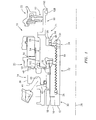
- FIG. 1 is a cross-sectional illustration of a shaft assembly 10 for a gas turbine engine.
- the shaft assembly 10 includes an engine shaft 12, one or more annular rotors 14, 16, 18, one or more annular stators 20, 22, and one or more annular stack nuts 24, 26.
- the shaft 12 is rotatable about an axial centerline 28.
- the shaft 12 includes an axially extending first shaft segment 30 and an axially extending threaded shaft segment 32 with a castellated end 34.
- the rotors may include a first rotor 14, a second rotor 16 and a third rotor 18.
- the first rotor 14 includes a clamping segment 36, a sealing segment 38 and a bridge segment 40.
- the clamping segment 36 extends axially between a first radial clamping surface 42 and a second radial clamping surface 44.
- the sealing segment 38 extends axially between a first end 46 and a radial distortion resistant contact sealing surface 48 at a second end.
- the bridge segment 40 extends radially between the clamping segment 36 and the sealing segment 38.
- the stators may include a first stator 20 and a second stator 22.
- the first stator 20 includes a radial contact sealing surface 50.
- the second stator 22 includes an annular seal 52 (e.g., a brush seal, a knife edge seal, a contact seal surface, a sacrificial seal surface, etc.).
- the stack nuts may include a first stack nut 24 and a second stack nut 26.
- FIG. 2 is a cross-sectional illustration of the first stack nut 24.
- FIGS. 3 and 4 are perspective illustrations of the first stack nut 24.
- the first stack nut 24 includes an annular base nut segment 54, an annular clamping nut segment 56, an annular torquing nut segment 58, and an annular seal land nut segment 60.
- the base nut segment 54 extends radially between a threaded nut bore 62 and an axial exterior nut surface 64.
- the base nut segment 54 extends axially between a first radial surface 66 and a second radial surface 68.
- the clamping nut segment 56 extends axially from the base nut segment 54, adjacent the first radial surface 66, to a distortion resistant load bearing surface 70.
- the load bearing surface 70 at least partially radially overlaps an intersection 72 between the clamping nut segment 56 and the base nut segment 54.
- the clamping nut segment 56 also extends radially between a radial inner, axial surface 74 and the exterior nut surface 64.
- an annular channel 76 extends into a corner between the radial inner, axial surface 74 and the first radial surface 66.
- the channel 76 may extend diagonally (e.g., along an axis acute to the centerline 28) such that a radial thickness of the clamping nut segment 56 decreases as the clamping nut segment 56 extends from the load bearing surface 70 towards the base nut segment 54.
- the channel 76 is disposed radially between a radial inner end 78 of the load bearing surface 70 and the base nut segment 54.
- the channel 76 may include an end 80 with a curved (e.g., arcuate, semi-circular, etc.) cross-sectional geometry.
- the torquing nut segment 58 extends axially from the base nut segment 54, adjacent the second radial surface 68, to a seal land nut segment contact surface 82.
- the torquing nut segment 58 extends radially between an inner castellated bore 84 and the exterior nut surface 64.
- the castellated bore 84 includes a plurality of radially inward extending protrusions 86 (e.g., splines).
- the protrusions 86 are sized and circumferentially arranged to mate with corresponding notches in a tool (not shown) for screwing the first stack nut 24 onto the threaded shaft segment 32 (see FIG. 1 ).
- Each protrusion 86 may include a circumferentially extending notch 88.
- the seal land nut segment 60 includes a seal segment 90 that extends axially from a torquing nut segment contact surface 92 to a channeled segment 94.
- the seal segment 90 extends radially between a radial inner, axial surface 96 and a radial outer, axial seal land surface 98.
- the channeled segment 94 includes a circumferentially extending channel 100.
- the torquing nut segment contact surface 92 is connected (e.g., welded) to the seal land nut segment contact surface 82.
- the second rotor 16 is disposed on the first shaft segment 30, and fixedly secured between the second stack nut 26 and a shaft shoulder (not shown).
- the third rotor 18 is disposed on and fixedly secured to the second rotor 16 and the second stack nut 26.
- the clamping segment 36 is disposed on the third rotor 18, and fixedly secured between the clamping segment 36 and a shaft shoulder (not shown).
- the threaded nut bore 62 is threaded onto the threaded shaft segment 32 such that the load bearing surface 70 exerts an axial clamp force against the second radial clamping surface 44.
- the radial contact sealing surface 50 contacts the distortion resistant contact sealing surface 48 forming a seal therebetween.
- the annular seal 52 engages the axial seal land surface forming a seal therebetween.
- An anti-rotation washer 102 may be arranged between the load bearing surface 70 and the second radial clamping surface 44 to prevent the first rotor 14 from rotating as the stack nut is threaded onto the shaft 12.
- a keyed washer 104 may be mated with the castellated bore 84 and the castellated end 34 of the threaded shaft segment 32 to prevent rotation of the first stack nut 24 during engine operation.
- a retaining ring 106 may be seated within the notches 88 to hold the keyed washer 104 in position.
- a damping ring 108 may be seated within the channel 100 to dampen vibrations within the first stack nut 24.
- the first stack nut 24 may be subjected to a thermal gradient.
- the thermal gradient may cause different regions of the first stack nut 24 to thermally expand at different rates.
- the segments of the first stack nut 24 are configured to thermally expand in a manner that may maintain a substantially uniform axial clamp force against the second radial clamping surface 44.
- the clamping nut segment 56 may thermally expand in a manner that maintains the load bearing surface 70 in a substantially perpendicular orientation relative to the shaft 12. Disruptive effects to the seal between the first rotor 14 and the first stator 20 caused by thermal expansion within the first stack nut 24 therefore may be reduced relative to prior art shaft assemblies.
- the first stack nut 24 may be configured such that the load bearing surface 70 cones towards or away from the first rotor 14 in order to increase or reduce the axial force against the second radial clamping surface 44.
- the seal land nut segment 60 may be formed integral with the torquing nut segment 58.
- the clamping nut segment 56 and/or the torquing nut segment 58 may be connected (e.g., welded) to the base nut segment 54.
- clamping nut segment 56, the torquing nut segment 58 and/or the seal land nut segment 60 may be omitted from the first stack nut 24.
Description
- This disclosure relates to a shaft assembly for a gas turbine engine that includes a stack nut.
- Various shaft assemblies for gas turbine engines are known in the art. One type of shaft assembly includes an engine shaft, a rotor, a stack nut and a stator. The rotor is typically mounted onto the shaft between the stack nut and a shaft shoulder. The rotor includes a rotor contact sealing surface, and the stator includes a stator contact sealing surface. The rotor contact sealing surface is arranged in sealing contact with the stator contact sealing surface to reduce fluid leakage therebetween.
- During operation, the stack nut may be subject to a thermal gradient. The thermal gradient may cause different regions of the stack nut to thermally expand at different rates and warp. A clamping force exerted by the stack nut against the rotor therefore may become non-uniform. Such a non-uniform clamping force may cause the rotor to warp and disrupt the sealing contact between the rotor and stator contact sealing surfaces and, thus, allow fluid leakage therebetween. Such fluid leakage may disadvantageously reduce engine efficiency, increase engine wear, cause engine component failure, etc.
- A prior art shaft assembly, having the features of the preamble of claim 1, is disclosed in
EP-1217169 . Another prior art assembly is shown inUS-2011/0052372 . - According to the present invention, there is provided a shaft assembly as claimed in claim 1.
- The foregoing features and operation of the invention will become more apparent in light of the following description and the accompanying drawings.
-
-
FIG. 1 is a cross-sectional illustration of a shaft assembly for a gas turbine engine; -
FIG. 2 is a cross-sectional illustration of a stack nut included in the shaft assembly illustrated inFIG. 1 ; -
FIG. 3 is a perspective illustration of the stack nut illustrated inFIG. 2 ; and -
FIG. 4 is another perspective illustration of the stack nut illustrated inFIG. 2 . -
FIG. 1 is a cross-sectional illustration of ashaft assembly 10 for a gas turbine engine. Theshaft assembly 10 includes an engine shaft 12, one or moreannular rotors annular stators annular stack nuts - The shaft 12 is rotatable about an
axial centerline 28. The shaft 12 includes an axially extendingfirst shaft segment 30 and an axially extending threadedshaft segment 32 with a castellatedend 34. - The rotors may include a
first rotor 14, asecond rotor 16 and athird rotor 18. Thefirst rotor 14 includes aclamping segment 36, asealing segment 38 and abridge segment 40. Theclamping segment 36 extends axially between a firstradial clamping surface 42 and a secondradial clamping surface 44. The sealingsegment 38 extends axially between afirst end 46 and a radial distortion resistantcontact sealing surface 48 at a second end. Thebridge segment 40 extends radially between theclamping segment 36 and thesealing segment 38. An alternative example of a first rotor configuration is disclosed inU.S. Patent Applicant Serial No. 12/415,427 - The stators may include a
first stator 20 and asecond stator 22. Thefirst stator 20 includes a radialcontact sealing surface 50. Thesecond stator 22 includes an annular seal 52 (e.g., a brush seal, a knife edge seal, a contact seal surface, a sacrificial seal surface, etc.). The stack nuts may include afirst stack nut 24 and asecond stack nut 26. -
FIG. 2 is a cross-sectional illustration of thefirst stack nut 24.FIGS. 3 and 4 are perspective illustrations of thefirst stack nut 24. Referring toFIGS. 2-4 , thefirst stack nut 24 includes an annularbase nut segment 54, an annularclamping nut segment 56, an annulartorquing nut segment 58, and an annular sealland nut segment 60. - Referring to
FIG. 2 , thebase nut segment 54 extends radially between a threadednut bore 62 and an axialexterior nut surface 64. Thebase nut segment 54 extends axially between a firstradial surface 66 and a secondradial surface 68. - The
clamping nut segment 56 extends axially from thebase nut segment 54, adjacent the firstradial surface 66, to a distortion resistantload bearing surface 70. Theload bearing surface 70 at least partially radially overlaps anintersection 72 between theclamping nut segment 56 and thebase nut segment 54. Theclamping nut segment 56 also extends radially between a radial inner,axial surface 74 and theexterior nut surface 64. In some embodiments, anannular channel 76 extends into a corner between the radial inner,axial surface 74 and the firstradial surface 66. Thechannel 76 may extend diagonally (e.g., along an axis acute to the centerline 28) such that a radial thickness of theclamping nut segment 56 decreases as theclamping nut segment 56 extends from theload bearing surface 70 towards thebase nut segment 54. Thechannel 76 is disposed radially between a radialinner end 78 of theload bearing surface 70 and thebase nut segment 54. Thechannel 76 may include anend 80 with a curved (e.g., arcuate, semi-circular, etc.) cross-sectional geometry. - The
torquing nut segment 58 extends axially from thebase nut segment 54, adjacent the secondradial surface 68, to a seal land nut segment contact surface 82. Thetorquing nut segment 58 extends radially between an innercastellated bore 84 and theexterior nut surface 64. Referring toFIGS. 2 and4 , thecastellated bore 84 includes a plurality of radially inward extending protrusions 86 (e.g., splines). Theprotrusions 86 are sized and circumferentially arranged to mate with corresponding notches in a tool (not shown) for screwing thefirst stack nut 24 onto the threaded shaft segment 32 (seeFIG. 1 ). Eachprotrusion 86 may include a circumferentially extendingnotch 88. - Referring to
FIG. 2 , the sealland nut segment 60 includes aseal segment 90 that extends axially from a torquing nutsegment contact surface 92 to a channeledsegment 94. Theseal segment 90 extends radially between a radial inner,axial surface 96 and a radial outer, axialseal land surface 98. The channeledsegment 94 includes a circumferentially extendingchannel 100. The torquing nutsegment contact surface 92 is connected (e.g., welded) to the seal land nut segment contact surface 82. - Referring to
FIG. 1 , thesecond rotor 16 is disposed on thefirst shaft segment 30, and fixedly secured between thesecond stack nut 26 and a shaft shoulder (not shown). Thethird rotor 18 is disposed on and fixedly secured to thesecond rotor 16 and thesecond stack nut 26. Theclamping segment 36 is disposed on thethird rotor 18, and fixedly secured between theclamping segment 36 and a shaft shoulder (not shown). In particular, the threadednut bore 62 is threaded onto the threadedshaft segment 32 such that theload bearing surface 70 exerts an axial clamp force against the secondradial clamping surface 44. The radialcontact sealing surface 50 contacts the distortion resistantcontact sealing surface 48 forming a seal therebetween. Theannular seal 52 engages the axial seal land surface forming a seal therebetween. - An
anti-rotation washer 102 may be arranged between theload bearing surface 70 and the secondradial clamping surface 44 to prevent thefirst rotor 14 from rotating as the stack nut is threaded onto the shaft 12. Akeyed washer 104 may be mated with thecastellated bore 84 and thecastellated end 34 of the threadedshaft segment 32 to prevent rotation of thefirst stack nut 24 during engine operation. A retainingring 106 may be seated within thenotches 88 to hold thekeyed washer 104 in position. A dampingring 108 may be seated within thechannel 100 to dampen vibrations within thefirst stack nut 24. - During operation, the
first stack nut 24 may be subjected to a thermal gradient. The thermal gradient may cause different regions of thefirst stack nut 24 to thermally expand at different rates. In contrast to the stack nut described above in the background section, however, the segments of thefirst stack nut 24 are configured to thermally expand in a manner that may maintain a substantially uniform axial clamp force against the secondradial clamping surface 44. The clampingnut segment 56, for example, may thermally expand in a manner that maintains theload bearing surface 70 in a substantially perpendicular orientation relative to the shaft 12. Disruptive effects to the seal between thefirst rotor 14 and thefirst stator 20 caused by thermal expansion within thefirst stack nut 24 therefore may be reduced relative to prior art shaft assemblies. - In some embodiments, the
first stack nut 24 may be configured such that theload bearing surface 70 cones towards or away from thefirst rotor 14 in order to increase or reduce the axial force against the secondradial clamping surface 44. - In some embodiments, the seal
land nut segment 60 may be formed integral with the torquingnut segment 58. In other embodiments, the clampingnut segment 56 and/or the torquingnut segment 58 may be connected (e.g., welded) to thebase nut segment 54. - In some embodiments, the clamping
nut segment 56, the torquingnut segment 58 and/or the sealland nut segment 60 may be omitted from thefirst stack nut 24. - While various embodiments of the present invention have been disclosed, it will be apparent to those of ordinary skill in the art that many more embodiments and implementations are possible within the scope of the invention. Accordingly, the present invention is not to be restricted except in light of the attached claims and their equivalents.
Claims (11)
- A shaft assembly for a gas turbine engine, comprising:a shaft (12) comprising a threaded shaft segment (32);an annular rotor (14) disposed on the shaft (12); andan annular stack nut (24) comprising
a base nut segment (54) comprising a threaded nut bore (62) that is mated with the threaded shaft segment (32); and
a clamping nut segment (56) axially extending from the base nut segment (54) to a load bearing surface (70), and comprising a radial thickness that decreases as the clamping nut segment (56) extends from the load bearing surface (70) towards the base nut segment (54), wherein the load bearing surface (70) exerts a force against the annular rotor (14), securing the annular rotor (14) to the shaft (12),
characterised in that:the annular stack nut (24) further comprises an annular channel (76) that extends diagonally into a radially inner, axial surface (74) of the clamping nut segment (56) and a radial surface (66) of the base nut segment (54). - The shaft assembly of claim 1, wherein the load bearing surface (70) at least partially radially overlaps an intersection (72) between the clamping nut segment (56) and the base nut segment (54).
- The shaft assembly of claim 1 or 2, wherein the load bearing surface (70) remains substantially perpendicular to the shaft (12) as a temperature of the annular stack nut (24) changes during engine operation.
- The shaft assembly of any of claims 1 to 3, wherein the annular channel (76) is disposed radially between a radial inner end (78) of the load bearing surface (70) and the base nut segment (54).
- The shaft assembly of any preceding claim, wherein the annular channel (76) comprises an end (80) with a curved cross-sectional geometry.
- The shaft assembly of any preceding claim, wherein the annular stack nut (24) further comprises a torquing nut (58) segment comprising an inner castellated bore (84), and the base nut segment (54) is connected axially between the clamping nut segment (56) and the torquing nut segment (58).
- The shaft assembly of any preceding claim, further comprising an annular seal (52) that engages a seal land nut segment (60) of the annular stack nut (24), wherein the base nut segment (54) is connected axially between the clamping nut segment (56) and the seal land nut segment (60).
- The shaft assembly of claim 7, wherein the annular stack nut (24) further comprises a torquing nut segment (58) connected axially between the base nut segment (54) and the seal land nut segment (60), and the torquing nut segment (58) comprises an inner castellated bore (84).
- The shaft assembly of claim 8, wherein the annular seal (52) engages an axial seal land surface (98) of the seal land nut segment (60).
- The shaft assembly of claim 8 or 9, wherein the annular stack nut (24) further comprises a clamping nut segment (56) axially extending from the base nut segment (54) to the load bearing surface (70), and comprising a radial thickness that decreases as the clamping nut segment (56) extends from the load bearing surface (70) towards the base nut segment (54).
- The shaft assembly of claim 10, wherein the load bearing surface (70) at least partially radially overlaps an intersection between the clamping nut segment (56) and the base nut segment (54).
Applications Claiming Priority (1)
| Application Number | Priority Date | Filing Date | Title |
|---|---|---|---|
| US13/267,539 US8932011B2 (en) | 2011-10-06 | 2011-10-06 | Shaft assembly for a gas turbine engine |
Publications (3)
| Publication Number | Publication Date |
|---|---|
| EP2639403A2 EP2639403A2 (en) | 2013-09-18 |
| EP2639403A3 EP2639403A3 (en) | 2013-12-11 |
| EP2639403B1 true EP2639403B1 (en) | 2015-05-27 |
Family
ID=47142923
Family Applications (1)
| Application Number | Title | Priority Date | Filing Date |
|---|---|---|---|
| EP12187480.4A Active EP2639403B1 (en) | 2011-10-06 | 2012-10-05 | Shaft Assembly for a Gas Turbine Engine |
Country Status (2)
| Country | Link |
|---|---|
| US (1) | US8932011B2 (en) |
| EP (1) | EP2639403B1 (en) |
Families Citing this family (7)
| Publication number | Priority date | Publication date | Assignee | Title |
|---|---|---|---|---|
| US8875378B2 (en) * | 2011-11-07 | 2014-11-04 | United Technologies Corporation | Tie bolt employing differential thread |
| US10094277B2 (en) * | 2014-06-20 | 2018-10-09 | United Technologies Corporation | Gas turbine engine configured for modular assembly/disassembly and method for same |
| FR3068391B1 (en) * | 2017-06-30 | 2020-07-17 | Safran Aircraft Engines | ASSEMBLY FOR TURBOMACHINE MODULE, TURBOMACHINE MODULE AND ASSOCIATED TURBOMACHINE |
| US10598020B2 (en) * | 2018-01-05 | 2020-03-24 | United Technologies Corporation | Spanner nut centering feature |
| US10927709B2 (en) | 2018-06-05 | 2021-02-23 | Raytheon Technologies Corporation | Turbine bearing stack load bypass nut |
| US11719283B2 (en) * | 2019-04-09 | 2023-08-08 | Rolls-Royce North American Technologies, Inc. | Axially clamping rotating engine components |
| US11415062B2 (en) | 2020-11-18 | 2022-08-16 | Raytheon Technologies Corporation | Rotating sleeve controlling clearance of seal assembly of gas turbine engine |
Family Cites Families (23)
| Publication number | Priority date | Publication date | Assignee | Title |
|---|---|---|---|---|
| US3602535A (en) * | 1970-05-14 | 1971-08-31 | Gen Motors Corp | Shaft coupling |
| US3718957A (en) * | 1970-09-03 | 1973-03-06 | Avco Corp | Method of securing a threaded element in a high centrifugal force field |
| BE789470A (en) * | 1971-09-30 | 1973-01-15 | Gen Electric | FIXING DEVICE AND TOOL FOR IT |
| US3823553A (en) * | 1972-12-26 | 1974-07-16 | Gen Electric | Gas turbine with removable self contained power turbine module |
| US4611464A (en) * | 1984-05-02 | 1986-09-16 | United Technologies Corporation | Rotor assembly for a gas turbine engine and method of disassembly |
| GB2223083B (en) * | 1988-09-27 | 1993-01-06 | Pratt & Whitney Canada | Shaft coupling for gas turbine engine |
| US5220784A (en) * | 1991-06-27 | 1993-06-22 | Allied-Signal Inc. | Gas turbine engine module assembly |
| US5533863A (en) | 1993-03-26 | 1996-07-09 | Allied Signal Inc | Self positioning nut |
| US5580183A (en) * | 1994-04-29 | 1996-12-03 | United Technologies Corporation | Gas turbine engine spline arrangement |
| US5537814A (en) * | 1994-09-28 | 1996-07-23 | General Electric Company | High pressure gas generator rotor tie rod system for gas turbine engine |
| US5626347A (en) | 1994-09-29 | 1997-05-06 | Alliedsignal Inc. | Coning resistant face seal having a "U" shape |
| CA2239460C (en) | 1996-01-19 | 2005-09-06 | Alliedsignal Inc. | Circumferential seal with ceramic rotor |
| US6375421B1 (en) * | 2000-01-31 | 2002-04-23 | General Electric Company | Piggyback rotor blisk |
| US6428272B1 (en) * | 2000-12-22 | 2002-08-06 | General Electric Company | Bolted joint for rotor disks and method of reducing thermal gradients therein |
| US7410173B2 (en) | 2003-05-01 | 2008-08-12 | Justak John F | Hydrodynamic brush seal |
| FR2857708B1 (en) * | 2003-07-15 | 2005-09-23 | Snecma Moteurs | IMPROVED DEVICE FOR FASTENING A MOTOR SHAFT ON A BEARING BRACKET |
| US7926260B2 (en) | 2006-07-05 | 2011-04-19 | United Technologies Corporation | Flexible shaft for gas turbine engine |
| US20090205341A1 (en) | 2008-02-20 | 2009-08-20 | Muldoon Marc J | Gas turbine engine with twin towershaft accessory gearbox |
| US8167314B2 (en) | 2009-03-31 | 2012-05-01 | United Technologies Corporation | Distortion resistant face seal counterface system |
| US20100303610A1 (en) | 2009-05-29 | 2010-12-02 | United Technologies Corporation | Cooled gas turbine stator assembly |
| US8186939B2 (en) * | 2009-08-25 | 2012-05-29 | Pratt & Whitney Canada Corp. | Turbine disc and retaining nut arrangement |
| US8650885B2 (en) | 2009-12-22 | 2014-02-18 | United Technologies Corporation | Retaining member for use with gas turbine engine shaft and method of assembly |
| US8517687B2 (en) | 2010-03-10 | 2013-08-27 | United Technologies Corporation | Gas turbine engine compressor and turbine section assembly utilizing tie shaft |
-
2011
- 2011-10-06 US US13/267,539 patent/US8932011B2/en active Active
-
2012
- 2012-10-05 EP EP12187480.4A patent/EP2639403B1/en active Active
Also Published As
| Publication number | Publication date |
|---|---|
| EP2639403A2 (en) | 2013-09-18 |
| EP2639403A3 (en) | 2013-12-11 |
| US8932011B2 (en) | 2015-01-13 |
| US20130089432A1 (en) | 2013-04-11 |
Similar Documents
| Publication | Publication Date | Title |
|---|---|---|
| EP2639403B1 (en) | Shaft Assembly for a Gas Turbine Engine | |
| US10858959B2 (en) | Axially divided turbomachine inner ring | |
| US20200032653A1 (en) | Retention of a rotor of an electronically-controlled turbomachine | |
| EP3208502B1 (en) | Ceramic seal runner and mount for a rotating shaft | |
| JP5634715B2 (en) | Method for manufacturing compliant plate seal assembly | |
| EP2372100B1 (en) | Liftoff carbon seal | |
| EP2660426B1 (en) | Turbine assembly | |
| US10760583B2 (en) | Axial bearing arrangement for a drive shaft of a centrifugal compressor | |
| JP6126342B2 (en) | Shaft assembly for gas turbine engines | |
| US9127559B2 (en) | Diaphragm for turbomachines and method of manufacture | |
| US20080193290A1 (en) | Hook Ring Segment For A Compressor Vane | |
| US8534673B2 (en) | Inter stage seal housing having a replaceable wear strip | |
| WO2014134260A1 (en) | Replaceable axial journal for auxiliary bearings | |
| US20190301295A1 (en) | Cross key anti-rotation spacer | |
| US6637942B2 (en) | Bearing assembly and method | |
| US9982604B2 (en) | Multi-stage inter shaft ring seal | |
| EP3561240B1 (en) | Carbon seal | |
| US7497658B2 (en) | Stacked reaction steam turbine stator assembly | |
| EP3527801B1 (en) | Pressure balanced secondary seal | |
| CN112534119A (en) | Rotor with a rotor component arranged between two rotor disks | |
| US10036474B2 (en) | Vented lift off seal assemblies | |
| US20130071055A1 (en) | Fluid-riding device | |
| CN114402121A (en) | Assembly for a turbomachine | |
| WO2016100212A1 (en) | Hydrodynamic seal assembly with interface control | |
| JP2008095794A (en) | Creep preventing rolling bearing and rolling bearing device |
Legal Events
| Date | Code | Title | Description |
|---|---|---|---|
| PUAI | Public reference made under article 153(3) epc to a published international application that has entered the european phase |
Free format text: ORIGINAL CODE: 0009012 |
|
| AK | Designated contracting states |
Kind code of ref document: A2 Designated state(s): AL AT BE BG CH CY CZ DE DK EE ES FI FR GB GR HR HU IE IS IT LI LT LU LV MC MK MT NL NO PL PT RO RS SE SI SK SM TR |
|
| AX | Request for extension of the european patent |
Extension state: BA ME |
|
| PUAL | Search report despatched |
Free format text: ORIGINAL CODE: 0009013 |
|
| AK | Designated contracting states |
Kind code of ref document: A3 Designated state(s): AL AT BE BG CH CY CZ DE DK EE ES FI FR GB GR HR HU IE IS IT LI LT LU LV MC MK MT NL NO PL PT RO RS SE SI SK SM TR |
|
| AX | Request for extension of the european patent |
Extension state: BA ME |
|
| RIC1 | Information provided on ipc code assigned before grant |
Ipc: F01D 5/02 20060101AFI20131106BHEP Ipc: F01D 5/06 20060101ALI20131106BHEP |
|
| 17P | Request for examination filed |
Effective date: 20140605 |
|
| RBV | Designated contracting states (corrected) |
Designated state(s): AL AT BE BG CH CY CZ DE DK EE ES FI FR GB GR HR HU IE IS IT LI LT LU LV MC MK MT NL NO PL PT RO RS SE SI SK SM TR |
|
| GRAP | Despatch of communication of intention to grant a patent |
Free format text: ORIGINAL CODE: EPIDOSNIGR1 |
|
| INTG | Intention to grant announced |
Effective date: 20141211 |
|
| GRAS | Grant fee paid |
Free format text: ORIGINAL CODE: EPIDOSNIGR3 |
|
| GRAA | (expected) grant |
Free format text: ORIGINAL CODE: 0009210 |
|
| AK | Designated contracting states |
Kind code of ref document: B1 Designated state(s): AL AT BE BG CH CY CZ DE DK EE ES FI FR GB GR HR HU IE IS IT LI LT LU LV MC MK MT NL NO PL PT RO RS SE SI SK SM TR |
|
| REG | Reference to a national code |
Ref country code: GB Ref legal event code: FG4D |
|
| REG | Reference to a national code |
Ref country code: CH Ref legal event code: EP |
|
| REG | Reference to a national code |
Ref country code: AT Ref legal event code: REF Ref document number: 728980 Country of ref document: AT Kind code of ref document: T Effective date: 20150615 |
|
| REG | Reference to a national code |
Ref country code: IE Ref legal event code: FG4D |
|
| REG | Reference to a national code |
Ref country code: DE Ref legal event code: R096 Ref document number: 602012007539 Country of ref document: DE |
|
| REG | Reference to a national code |
Ref country code: AT Ref legal event code: MK05 Ref document number: 728980 Country of ref document: AT Kind code of ref document: T Effective date: 20150527 |
|
| REG | Reference to a national code |
Ref country code: LT Ref legal event code: MG4D |
|
| PG25 | Lapsed in a contracting state [announced via postgrant information from national office to epo] |
Ref country code: NO Free format text: LAPSE BECAUSE OF FAILURE TO SUBMIT A TRANSLATION OF THE DESCRIPTION OR TO PAY THE FEE WITHIN THE PRESCRIBED TIME-LIMIT Effective date: 20150827 Ref country code: LT Free format text: LAPSE BECAUSE OF FAILURE TO SUBMIT A TRANSLATION OF THE DESCRIPTION OR TO PAY THE FEE WITHIN THE PRESCRIBED TIME-LIMIT Effective date: 20150527 Ref country code: HR Free format text: LAPSE BECAUSE OF FAILURE TO SUBMIT A TRANSLATION OF THE DESCRIPTION OR TO PAY THE FEE WITHIN THE PRESCRIBED TIME-LIMIT Effective date: 20150527 Ref country code: PT Free format text: LAPSE BECAUSE OF FAILURE TO SUBMIT A TRANSLATION OF THE DESCRIPTION OR TO PAY THE FEE WITHIN THE PRESCRIBED TIME-LIMIT Effective date: 20150928 Ref country code: FI Free format text: LAPSE BECAUSE OF FAILURE TO SUBMIT A TRANSLATION OF THE DESCRIPTION OR TO PAY THE FEE WITHIN THE PRESCRIBED TIME-LIMIT Effective date: 20150527 Ref country code: ES Free format text: LAPSE BECAUSE OF FAILURE TO SUBMIT A TRANSLATION OF THE DESCRIPTION OR TO PAY THE FEE WITHIN THE PRESCRIBED TIME-LIMIT Effective date: 20150527 |
|
| REG | Reference to a national code |
Ref country code: NL Ref legal event code: MP Effective date: 20150527 |
|
| PG25 | Lapsed in a contracting state [announced via postgrant information from national office to epo] |
Ref country code: GR Free format text: LAPSE BECAUSE OF FAILURE TO SUBMIT A TRANSLATION OF THE DESCRIPTION OR TO PAY THE FEE WITHIN THE PRESCRIBED TIME-LIMIT Effective date: 20150828 Ref country code: AT Free format text: LAPSE BECAUSE OF FAILURE TO SUBMIT A TRANSLATION OF THE DESCRIPTION OR TO PAY THE FEE WITHIN THE PRESCRIBED TIME-LIMIT Effective date: 20150527 Ref country code: IS Free format text: LAPSE BECAUSE OF FAILURE TO SUBMIT A TRANSLATION OF THE DESCRIPTION OR TO PAY THE FEE WITHIN THE PRESCRIBED TIME-LIMIT Effective date: 20150927 Ref country code: LV Free format text: LAPSE BECAUSE OF FAILURE TO SUBMIT A TRANSLATION OF THE DESCRIPTION OR TO PAY THE FEE WITHIN THE PRESCRIBED TIME-LIMIT Effective date: 20150527 Ref country code: BG Free format text: LAPSE BECAUSE OF FAILURE TO SUBMIT A TRANSLATION OF THE DESCRIPTION OR TO PAY THE FEE WITHIN THE PRESCRIBED TIME-LIMIT Effective date: 20150827 Ref country code: RS Free format text: LAPSE BECAUSE OF FAILURE TO SUBMIT A TRANSLATION OF THE DESCRIPTION OR TO PAY THE FEE WITHIN THE PRESCRIBED TIME-LIMIT Effective date: 20150527 |
|
| PG25 | Lapsed in a contracting state [announced via postgrant information from national office to epo] |
Ref country code: DK Free format text: LAPSE BECAUSE OF FAILURE TO SUBMIT A TRANSLATION OF THE DESCRIPTION OR TO PAY THE FEE WITHIN THE PRESCRIBED TIME-LIMIT Effective date: 20150527 Ref country code: EE Free format text: LAPSE BECAUSE OF FAILURE TO SUBMIT A TRANSLATION OF THE DESCRIPTION OR TO PAY THE FEE WITHIN THE PRESCRIBED TIME-LIMIT Effective date: 20150527 |
|
| PG25 | Lapsed in a contracting state [announced via postgrant information from national office to epo] |
Ref country code: PL Free format text: LAPSE BECAUSE OF FAILURE TO SUBMIT A TRANSLATION OF THE DESCRIPTION OR TO PAY THE FEE WITHIN THE PRESCRIBED TIME-LIMIT Effective date: 20150527 Ref country code: SK Free format text: LAPSE BECAUSE OF FAILURE TO SUBMIT A TRANSLATION OF THE DESCRIPTION OR TO PAY THE FEE WITHIN THE PRESCRIBED TIME-LIMIT Effective date: 20150527 Ref country code: CZ Free format text: LAPSE BECAUSE OF FAILURE TO SUBMIT A TRANSLATION OF THE DESCRIPTION OR TO PAY THE FEE WITHIN THE PRESCRIBED TIME-LIMIT Effective date: 20150527 Ref country code: RO Free format text: LAPSE BECAUSE OF NON-PAYMENT OF DUE FEES Effective date: 20150527 |
|
| REG | Reference to a national code |
Ref country code: DE Ref legal event code: R097 Ref document number: 602012007539 Country of ref document: DE |
|
| PLBE | No opposition filed within time limit |
Free format text: ORIGINAL CODE: 0009261 |
|
| STAA | Information on the status of an ep patent application or granted ep patent |
Free format text: STATUS: NO OPPOSITION FILED WITHIN TIME LIMIT |
|
| PG25 | Lapsed in a contracting state [announced via postgrant information from national office to epo] |
Ref country code: IT Free format text: LAPSE BECAUSE OF FAILURE TO SUBMIT A TRANSLATION OF THE DESCRIPTION OR TO PAY THE FEE WITHIN THE PRESCRIBED TIME-LIMIT Effective date: 20150527 |
|
| 26N | No opposition filed |
Effective date: 20160301 |
|
| PG25 | Lapsed in a contracting state [announced via postgrant information from national office to epo] |
Ref country code: SI Free format text: LAPSE BECAUSE OF FAILURE TO SUBMIT A TRANSLATION OF THE DESCRIPTION OR TO PAY THE FEE WITHIN THE PRESCRIBED TIME-LIMIT Effective date: 20150527 Ref country code: LU Free format text: LAPSE BECAUSE OF FAILURE TO SUBMIT A TRANSLATION OF THE DESCRIPTION OR TO PAY THE FEE WITHIN THE PRESCRIBED TIME-LIMIT Effective date: 20151005 |
|
| REG | Reference to a national code |
Ref country code: CH Ref legal event code: PL |
|
| PG25 | Lapsed in a contracting state [announced via postgrant information from national office to epo] |
Ref country code: MC Free format text: LAPSE BECAUSE OF FAILURE TO SUBMIT A TRANSLATION OF THE DESCRIPTION OR TO PAY THE FEE WITHIN THE PRESCRIBED TIME-LIMIT Effective date: 20150527 |
|
| REG | Reference to a national code |
Ref country code: IE Ref legal event code: MM4A |
|
| PG25 | Lapsed in a contracting state [announced via postgrant information from national office to epo] |
Ref country code: CH Free format text: LAPSE BECAUSE OF NON-PAYMENT OF DUE FEES Effective date: 20151031 Ref country code: LI Free format text: LAPSE BECAUSE OF NON-PAYMENT OF DUE FEES Effective date: 20151031 |
|
| REG | Reference to a national code |
Ref country code: FR Ref legal event code: ST Effective date: 20160630 |
|
| PG25 | Lapsed in a contracting state [announced via postgrant information from national office to epo] |
Ref country code: FR Free format text: LAPSE BECAUSE OF NON-PAYMENT OF DUE FEES Effective date: 20151102 Ref country code: BE Free format text: LAPSE BECAUSE OF FAILURE TO SUBMIT A TRANSLATION OF THE DESCRIPTION OR TO PAY THE FEE WITHIN THE PRESCRIBED TIME-LIMIT Effective date: 20150527 |
|
| PG25 | Lapsed in a contracting state [announced via postgrant information from national office to epo] |
Ref country code: IE Free format text: LAPSE BECAUSE OF NON-PAYMENT OF DUE FEES Effective date: 20151005 |
|
| PG25 | Lapsed in a contracting state [announced via postgrant information from national office to epo] |
Ref country code: SM Free format text: LAPSE BECAUSE OF FAILURE TO SUBMIT A TRANSLATION OF THE DESCRIPTION OR TO PAY THE FEE WITHIN THE PRESCRIBED TIME-LIMIT Effective date: 20150527 Ref country code: HU Free format text: LAPSE BECAUSE OF FAILURE TO SUBMIT A TRANSLATION OF THE DESCRIPTION OR TO PAY THE FEE WITHIN THE PRESCRIBED TIME-LIMIT; INVALID AB INITIO Effective date: 20121005 |
|
| PG25 | Lapsed in a contracting state [announced via postgrant information from national office to epo] |
Ref country code: CY Free format text: LAPSE BECAUSE OF FAILURE TO SUBMIT A TRANSLATION OF THE DESCRIPTION OR TO PAY THE FEE WITHIN THE PRESCRIBED TIME-LIMIT Effective date: 20150527 Ref country code: NL Free format text: LAPSE BECAUSE OF FAILURE TO SUBMIT A TRANSLATION OF THE DESCRIPTION OR TO PAY THE FEE WITHIN THE PRESCRIBED TIME-LIMIT Effective date: 20150527 Ref country code: SE Free format text: LAPSE BECAUSE OF FAILURE TO SUBMIT A TRANSLATION OF THE DESCRIPTION OR TO PAY THE FEE WITHIN THE PRESCRIBED TIME-LIMIT Effective date: 20150527 |
|
| REG | Reference to a national code |
Ref country code: DE Ref legal event code: R082 Ref document number: 602012007539 Country of ref document: DE Representative=s name: SCHMITT-NILSON SCHRAUD WAIBEL WOHLFROM PATENTA, DE |
|
| REG | Reference to a national code |
Ref country code: DE Ref legal event code: R082 Ref document number: 602012007539 Country of ref document: DE Representative=s name: SCHMITT-NILSON SCHRAUD WAIBEL WOHLFROM PATENTA, DE Ref country code: DE Ref legal event code: R081 Ref document number: 602012007539 Country of ref document: DE Owner name: UNITED TECHNOLOGIES CORP. (N.D.GES.D. STAATES , US Free format text: FORMER OWNER: UNITED TECHNOLOGIES CORP., HARTFORD, CONN., US |
|
| PG25 | Lapsed in a contracting state [announced via postgrant information from national office to epo] |
Ref country code: MT Free format text: LAPSE BECAUSE OF FAILURE TO SUBMIT A TRANSLATION OF THE DESCRIPTION OR TO PAY THE FEE WITHIN THE PRESCRIBED TIME-LIMIT Effective date: 20150527 |
|
| PG25 | Lapsed in a contracting state [announced via postgrant information from national office to epo] |
Ref country code: MK Free format text: LAPSE BECAUSE OF FAILURE TO SUBMIT A TRANSLATION OF THE DESCRIPTION OR TO PAY THE FEE WITHIN THE PRESCRIBED TIME-LIMIT Effective date: 20150527 Ref country code: TR Free format text: LAPSE BECAUSE OF FAILURE TO SUBMIT A TRANSLATION OF THE DESCRIPTION OR TO PAY THE FEE WITHIN THE PRESCRIBED TIME-LIMIT Effective date: 20150527 |
|
| PG25 | Lapsed in a contracting state [announced via postgrant information from national office to epo] |
Ref country code: AL Free format text: LAPSE BECAUSE OF FAILURE TO SUBMIT A TRANSLATION OF THE DESCRIPTION OR TO PAY THE FEE WITHIN THE PRESCRIBED TIME-LIMIT Effective date: 20150527 |
|
| REG | Reference to a national code |
Ref country code: DE Ref legal event code: R081 Ref document number: 602012007539 Country of ref document: DE Owner name: RAYTHEON TECHNOLOGIES CORPORATION (N.D.GES.D.S, US Free format text: FORMER OWNER: UNITED TECHNOLOGIES CORP. (N.D.GES.D. STAATES DELAWARE), FARMINGTON, CONN., US |
|
| P01 | Opt-out of the competence of the unified patent court (upc) registered |
Effective date: 20230520 |
|
| PGFP | Annual fee paid to national office [announced via postgrant information from national office to epo] |
Ref country code: GB Payment date: 20230920 Year of fee payment: 12 |
|
| PGFP | Annual fee paid to national office [announced via postgrant information from national office to epo] |
Ref country code: DE Payment date: 20230920 Year of fee payment: 12 |