EP1217169A2 - Cooled bolted joint for rotor disks - Google Patents
Cooled bolted joint for rotor disks Download PDFInfo
- Publication number
- EP1217169A2 EP1217169A2 EP01310628A EP01310628A EP1217169A2 EP 1217169 A2 EP1217169 A2 EP 1217169A2 EP 01310628 A EP01310628 A EP 01310628A EP 01310628 A EP01310628 A EP 01310628A EP 1217169 A2 EP1217169 A2 EP 1217169A2
- Authority
- EP
- European Patent Office
- Prior art keywords
- bolt
- tube
- bolted joint
- channel
- rotor disk
- Prior art date
- Legal status (The legal status is an assumption and is not a legal conclusion. Google has not performed a legal analysis and makes no representation as to the accuracy of the status listed.)
- Granted
Links
Images


Classifications
-
- F—MECHANICAL ENGINEERING; LIGHTING; HEATING; WEAPONS; BLASTING
- F01—MACHINES OR ENGINES IN GENERAL; ENGINE PLANTS IN GENERAL; STEAM ENGINES
- F01D—NON-POSITIVE DISPLACEMENT MACHINES OR ENGINES, e.g. STEAM TURBINES
- F01D5/00—Blades; Blade-carrying members; Heating, heat-insulating, cooling or antivibration means on the blades or the members
- F01D5/02—Blade-carrying members, e.g. rotors
- F01D5/06—Rotors for more than one axial stage, e.g. of drum or multiple disc type; Details thereof, e.g. shafts, shaft connections
- F01D5/066—Connecting means for joining rotor-discs or rotor-elements together, e.g. by a central bolt, by clamps
-
- F—MECHANICAL ENGINEERING; LIGHTING; HEATING; WEAPONS; BLASTING
- F01—MACHINES OR ENGINES IN GENERAL; ENGINE PLANTS IN GENERAL; STEAM ENGINES
- F01D—NON-POSITIVE DISPLACEMENT MACHINES OR ENGINES, e.g. STEAM TURBINES
- F01D5/00—Blades; Blade-carrying members; Heating, heat-insulating, cooling or antivibration means on the blades or the members
- F01D5/02—Blade-carrying members, e.g. rotors
- F01D5/08—Heating, heat-insulating or cooling means
- F01D5/085—Heating, heat-insulating or cooling means cooling fluid circulating inside the rotor
-
- F—MECHANICAL ENGINEERING; LIGHTING; HEATING; WEAPONS; BLASTING
- F05—INDEXING SCHEMES RELATING TO ENGINES OR PUMPS IN VARIOUS SUBCLASSES OF CLASSES F01-F04
- F05D—INDEXING SCHEME FOR ASPECTS RELATING TO NON-POSITIVE-DISPLACEMENT MACHINES OR ENGINES, GAS-TURBINES OR JET-PROPULSION PLANTS
- F05D2260/00—Function
- F05D2260/20—Heat transfer, e.g. cooling
-
- Y—GENERAL TAGGING OF NEW TECHNOLOGICAL DEVELOPMENTS; GENERAL TAGGING OF CROSS-SECTIONAL TECHNOLOGIES SPANNING OVER SEVERAL SECTIONS OF THE IPC; TECHNICAL SUBJECTS COVERED BY FORMER USPC CROSS-REFERENCE ART COLLECTIONS [XRACs] AND DIGESTS
- Y02—TECHNOLOGIES OR APPLICATIONS FOR MITIGATION OR ADAPTATION AGAINST CLIMATE CHANGE
- Y02T—CLIMATE CHANGE MITIGATION TECHNOLOGIES RELATED TO TRANSPORTATION
- Y02T50/00—Aeronautics or air transport
- Y02T50/60—Efficient propulsion technologies, e.g. for aircraft
Definitions
- Rotating disks particularly those in the high pressure turbine section of an engine, develop high radial thermal gradients during transient operation because of exposure of the disk rim to hot gases.
- the rim of the disk has a quick thermal response (i.e., temperature increase) while the web and bore react more slowly due to their high relative mass and their lower temperature environment.
- the thermal gradient creates large tangential and radial stresses in the web and bore of the disk that are magnified by any stress concentrations such as holes, fillets and the like.
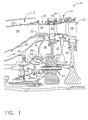
- the above-mentioned need is met by the present invention, which provides a bolted joint for connecting first and second rotor disks in a gas turbine engine.
- the bolted joint includes a bolt hole formed in the first rotor disk and a tube disposed in the bolt hole such that a channel is defined between the tube and the bolt hole.
- a bolt is disposed in the tube such that a gap is defined between the bolt and the tube.
- the gap thermally insulates the bolt from hot fluid in the channel.
- a first passage provides fluid communication between the channel and a forward cavity, and a second passage provides fluid communication between the channel and an aft cavity. Hot fluid passing through the channel reduces thermal gradients in the first rotor disk.
- the tube thermally shields the bolt from the hot fluid to minimize differential thermal growth.
- the foregoing has described a bolted joint that increases the thermal response of the disk web and bore through use of a parallel air delivery system.
- the increased thermal response reduces the thermal gradient in the rotor disk, which in turn reduces disk transient stresses.
- the bolt is thermally insulated to minimize loss of clamp load and low cycle fatigue problems.
Landscapes
- Engineering & Computer Science (AREA)
- Mechanical Engineering (AREA)
- General Engineering & Computer Science (AREA)
- Turbine Rotor Nozzle Sealing (AREA)
- Structures Of Non-Positive Displacement Pumps (AREA)
Abstract
Description
Claims (10)
- A bolted joint (52) for connecting first and second components (40,48), said bolted joint (52) comprising:a bolt hole (70) formed in said first component (40);a tube (82) disposed in said bolt hole (70), wherein a channel (84) is defined between said tube (82) and said bolt hole (70);a bolt (66) disposed in said tube (82), wherein a gap (88) is defined between said bolt (66) and said tube (82) and said gap (88) thermally insulates said bolt (66) from hot fluid in said channel (84);a first passage (96) providing fluid communication between said channel (84) and a first exterior cavity (63); anda second passage (98) providing fluid communication between said channel (84) and a second exterior cavity (42).
- The bolted joint (52) of claim 1 further comprising a nut (74) threadingly received on one end of said bolt (66) and a spacer (78) disposed on said bolt (66) adjacent to said nut (74), said first passage (96) being formed in said spacer (78).
- The bolted joint (52) of claim 2 wherein said tube (82) is joined to said spacer (78).
- The bolted joint (52) of any preceding claim wherein said second passage (98) is formed in said second component (48).
- The bolted joint (52) of any preceding claim further comprising a nut (174) threadingly received on one end of said bolt (66), said first passage (96) being formed in said nut (174).
- The bolted joint (52) of claim 5 wherein said tube (82) is joined to said nut (174).
- The bolted joint (52) of claim 5 wherein said second passage (98) is formed in said second component (48).
- A gas turbine engine (10) comprising a first rotor disk (40), a second rotor disk (48), a first cavity (63) adjacent to said first rotor disk (40), and a second cavity (42) adjacent to said second rotor disk (48), and a bolted joint (52) as claimed in any preceding claim and in which said first and second rotor disks (40,48) comprise said first and second components.
- A method of reducing thermal gradients in a first rotor disk (40) in a gas turbine engine (10) having a bolted joint (52) for connecting the first rotor disk (40) and a second rotor disk (48) wherein said bolted joint (52) includes a bolt (66) disposed in a bolt hole (70) formed in said first rotor disk (40), comprising:providing a channel (84) between said bolt (66) and said bolt hole (70);causing a relatively hot fluid to pass through said channel (84); andinsulating said bolt (66) from said hot fluid in said channel (84).
- The method of claim 9 wherein said relatively hot fluid is compressor discharge air.
Applications Claiming Priority (2)
| Application Number | Priority Date | Filing Date | Title |
|---|---|---|---|
| US747872 | 2000-12-22 | ||
| US09/747,872 US6428272B1 (en) | 2000-12-22 | 2000-12-22 | Bolted joint for rotor disks and method of reducing thermal gradients therein |
Publications (3)
| Publication Number | Publication Date |
|---|---|
| EP1217169A2 true EP1217169A2 (en) | 2002-06-26 |
| EP1217169A3 EP1217169A3 (en) | 2004-01-07 |
| EP1217169B1 EP1217169B1 (en) | 2007-07-18 |
Family
ID=25007012
Family Applications (1)
| Application Number | Title | Priority Date | Filing Date |
|---|---|---|---|
| EP01310628A Expired - Lifetime EP1217169B1 (en) | 2000-12-22 | 2001-12-19 | Bolted joint for rotor disks |
Country Status (6)
| Country | Link |
|---|---|
| US (1) | US6428272B1 (en) |
| EP (1) | EP1217169B1 (en) |
| JP (1) | JP4100902B2 (en) |
| BR (1) | BR0106243B1 (en) |
| CA (1) | CA2364768C (en) |
| DE (1) | DE60129403T2 (en) |
Cited By (3)
| Publication number | Priority date | Publication date | Assignee | Title |
|---|---|---|---|---|
| EP2639403A3 (en) * | 2011-10-06 | 2013-12-11 | United Technologies Corporation | Shaft Assembly for a Gas Turbine Engine |
| WO2015130497A1 (en) * | 2014-02-25 | 2015-09-03 | Siemens Energy, Inc. | Thermal shields for gas turbine rotor |
| EP3851632A1 (en) * | 2020-01-20 | 2021-07-21 | Raytheon Technologies Corporation | Gas turbine engine rotor stack with bushing having adaptive airflow temperature metering |
Families Citing this family (28)
| Publication number | Priority date | Publication date | Assignee | Title |
|---|---|---|---|---|
| US6784597B1 (en) | 2003-04-15 | 2004-08-31 | General Electric Company | Self-locking nut for stud shaft and stacked wheel assembly for the rotor of a rotary machine |
| JP2005054738A (en) * | 2003-08-07 | 2005-03-03 | Ishikawajima Harima Heavy Ind Co Ltd | Lubricating oil supply device for high-speed rotating machine and double-structure rotating shaft |
| FR2866057B1 (en) * | 2004-02-06 | 2006-04-28 | Snecma Moteurs | DEVICE FOR BALANCING A ROTOR DISC, DISC EQUIPPED WITH SUCH A DEVICE, AND ROTOR HAVING SUCH A DISK |
| DE102004016244B4 (en) * | 2004-04-02 | 2007-08-23 | Mtu Aero Engines Gmbh | Rotor for a turbomachine |
| FR2908153B1 (en) * | 2006-11-07 | 2011-05-13 | Snecma | DEVICE FOR HITCHING A DISTRIBUTOR (8) OF A TURBINE, TURBINE COMPRISING THEM, AND AN AIRCRAFT ENGINE WHICH IS EQUIPPED |
| US8240988B2 (en) * | 2008-03-26 | 2012-08-14 | Siemens Energy, Inc. | Fastener assembly with cyclone cooling |
| FR2935429B1 (en) * | 2008-08-26 | 2011-11-25 | Snecma | FIXED BLADE OF TURBOMACHINE WITH REDUCED MASS AND TURBOMACHINE COMPRISING AT LEAST ONE SUCH FIXED AUBAGE |
| DE102008060571A1 (en) * | 2008-12-04 | 2010-06-10 | Mtu Aero Engines Gmbh | Mounting device for a rotor system of an axial flow machine |
| US8186939B2 (en) * | 2009-08-25 | 2012-05-29 | Pratt & Whitney Canada Corp. | Turbine disc and retaining nut arrangement |
| US8727695B2 (en) * | 2009-12-09 | 2014-05-20 | Rolls-Royce Corporation | Chamfer-fillet gap for thermal management |
| US9863250B2 (en) * | 2010-02-24 | 2018-01-09 | United Technologies Corporation | Fastener aperture having an elongated geometry |
| GB201108842D0 (en) * | 2011-05-26 | 2011-07-06 | Rolls Royce Plc | A vortex reducer |
| US8932022B2 (en) | 2012-02-03 | 2015-01-13 | Pratt & Whitney Canada Corp. | Fastening system for fan and shaft interconnection |
| US9004871B2 (en) * | 2012-08-17 | 2015-04-14 | General Electric Company | Stacked wheel assembly for a turbine system and method of assembling |
| US9540945B2 (en) | 2013-03-01 | 2017-01-10 | Siemens Energy, Inc. | Active bypass flow control for a seal in a gas turbine engine |
| WO2014189589A2 (en) | 2013-03-06 | 2014-11-27 | Rolls-Royce North American Technologies, Inc. | Gas turbine engine with soft mounted pre-swirl nozzle |
| US10465519B2 (en) | 2013-10-17 | 2019-11-05 | Pratt & Whitney Canada Corp. | Fastening system for rotor hubs |
| DE102013226490A1 (en) | 2013-12-18 | 2015-06-18 | Rolls-Royce Deutschland Ltd & Co Kg | Chilled flange connection of a gas turbine engine |
| US10001061B2 (en) * | 2014-06-06 | 2018-06-19 | United Technologies Corporation | Cooling system for gas turbine engines |
| US9816387B2 (en) | 2014-09-09 | 2017-11-14 | United Technologies Corporation | Attachment faces for clamped turbine stator of a gas turbine engine |
| DE102014222060A1 (en) * | 2014-10-29 | 2016-05-04 | Siemens Aktiengesellschaft | Bolts, housing for a turbine, turbine and method for mounting a housing of a turbine |
| US20170107902A1 (en) * | 2015-10-19 | 2017-04-20 | General Electric Company | Systems and Methods for Wheel Space Temperature Management |
| US10336459B2 (en) * | 2016-02-01 | 2019-07-02 | Bell Helicopter Textron Inc. | Clamped splines for aircraft engine mount assemblies |
| DE102017214058A1 (en) | 2017-08-11 | 2019-02-14 | MTU Aero Engines AG | Rotor for a turbomachine |
| US11428104B2 (en) | 2019-07-29 | 2022-08-30 | Pratt & Whitney Canada Corp. | Partition arrangement for gas turbine engine and method |
| US11293294B2 (en) | 2020-05-22 | 2022-04-05 | Raytheon Technologies Corporation | Speed-controlled conditioning valve for high pressure compressor |
| CN115680798A (en) * | 2022-10-19 | 2023-02-03 | 南京航空航天大学 | Integrated turbine disc cooling structure |
| US12601262B1 (en) * | 2025-04-30 | 2026-04-14 | Honeywell International Inc. | Gas turbine engines, methods of securing rotating components therein with threaded nuts, and the threaded nuts |
Family Cites Families (15)
| Publication number | Priority date | Publication date | Assignee | Title |
|---|---|---|---|---|
| US2320398A (en) * | 1941-08-30 | 1943-06-01 | Westinghouse Electric & Mfg Co | Cooling high temperature bolting |
| DE1218800B (en) * | 1961-04-25 | 1966-06-08 | M A N Turbo Ges Mit Beschraenk | Gas turbine, in particular small gas turbine |
| US3905713A (en) * | 1974-02-28 | 1975-09-16 | Ingersoll Rand Co | Tie bolt sealing means |
| US4309145A (en) * | 1978-10-30 | 1982-01-05 | General Electric Company | Cooling air seal |
| US4247248A (en) * | 1978-12-20 | 1981-01-27 | United Technologies Corporation | Outer air seal support structure for gas turbine engine |
| JPS5958265A (en) * | 1982-09-27 | 1984-04-03 | Toshiba Corp | Device for tightening flanges of high-temperature fluid container |
| US4887949A (en) * | 1988-03-30 | 1989-12-19 | United Technologies Corporation | Bolt retention apparatus |
| US4991390A (en) * | 1988-09-26 | 1991-02-12 | Sundstrand Corporation | Mounting and cooling turbine nozzle vanes |
| US5116158A (en) * | 1988-12-06 | 1992-05-26 | Allied-Signal Inc. | High temperature turbine engine structure |
| US5072785A (en) * | 1990-06-12 | 1991-12-17 | United Technologies Corporation | Convectively cooled bolt assembly |
| US5129447A (en) * | 1991-05-20 | 1992-07-14 | United Technologies Corporation | Cooled bolting arrangement |
| US5226788A (en) * | 1991-12-23 | 1993-07-13 | General Electric Company | Turbine heat shield and bolt retainer assembly |
| US5350278A (en) * | 1993-06-28 | 1994-09-27 | The United States Of America As Represented By The Secretary Of The Air Force | Joining means for rotor discs |
| US5779416A (en) * | 1996-10-30 | 1998-07-14 | General Electric Co. | Bolt/stud and nut for enhanced high-cycle fatigue capability |
| US5848874A (en) * | 1997-05-13 | 1998-12-15 | United Technologies Corporation | Gas turbine stator vane assembly |
-
2000
- 2000-12-22 US US09/747,872 patent/US6428272B1/en not_active Expired - Lifetime
-
2001
- 2001-12-13 CA CA002364768A patent/CA2364768C/en not_active Expired - Fee Related
- 2001-12-19 DE DE60129403T patent/DE60129403T2/en not_active Expired - Lifetime
- 2001-12-19 EP EP01310628A patent/EP1217169B1/en not_active Expired - Lifetime
- 2001-12-21 BR BRPI0106243-3A patent/BR0106243B1/en not_active IP Right Cessation
- 2001-12-21 JP JP2001388705A patent/JP4100902B2/en not_active Expired - Fee Related
Cited By (7)
| Publication number | Priority date | Publication date | Assignee | Title |
|---|---|---|---|---|
| EP2639403A3 (en) * | 2011-10-06 | 2013-12-11 | United Technologies Corporation | Shaft Assembly for a Gas Turbine Engine |
| WO2015130497A1 (en) * | 2014-02-25 | 2015-09-03 | Siemens Energy, Inc. | Thermal shields for gas turbine rotor |
| CN106062314A (en) * | 2014-02-25 | 2016-10-26 | 西门子能源公司 | Heat shields for gas turbine rotors |
| US9771802B2 (en) | 2014-02-25 | 2017-09-26 | Siemens Energy, Inc. | Thermal shields for gas turbine rotor |
| EP3851632A1 (en) * | 2020-01-20 | 2021-07-21 | Raytheon Technologies Corporation | Gas turbine engine rotor stack with bushing having adaptive airflow temperature metering |
| US11352903B2 (en) | 2020-01-20 | 2022-06-07 | Raytheon Technologies Corporation | Rotor stack bushing with adaptive temperature metering for a gas turbine engine |
| US11555416B2 (en) | 2020-01-20 | 2023-01-17 | Raytheon Technologies Corporation | Rotor stack bushing with adaptive temperature metering for a gas turbine engine |
Also Published As
| Publication number | Publication date |
|---|---|
| CA2364768C (en) | 2007-09-11 |
| BR0106243B1 (en) | 2010-07-13 |
| BR0106243A (en) | 2002-08-13 |
| CA2364768A1 (en) | 2002-06-22 |
| EP1217169A3 (en) | 2004-01-07 |
| DE60129403T2 (en) | 2008-04-17 |
| US20020081199A1 (en) | 2002-06-27 |
| JP4100902B2 (en) | 2008-06-11 |
| DE60129403D1 (en) | 2007-08-30 |
| EP1217169B1 (en) | 2007-07-18 |
| JP2002242605A (en) | 2002-08-28 |
| US6428272B1 (en) | 2002-08-06 |
Similar Documents
| Publication | Publication Date | Title |
|---|---|---|
| EP1217169B1 (en) | Bolted joint for rotor disks | |
| US10995627B2 (en) | Turbine shroud with forward case and full hoop blade track | |
| EP1149986B1 (en) | Turbine frame assembly | |
| EP1491823B1 (en) | Rabbet mounted gas turbine combustor | |
| US6425738B1 (en) | Accordion nozzle | |
| US8240121B2 (en) | Retrofit dirt separator for gas turbine engine | |
| US8092163B2 (en) | Turbine stator mount | |
| US20200318831A1 (en) | Pressure regulated piston seal for a gas turbine combustor liner | |
| US8172522B2 (en) | Method and system for supporting stator components | |
| US11662096B2 (en) | Combustor swirler to pseudo-dome attachment and interface with a CMC dome | |
| CA2660179C (en) | A system and method for supporting stator components | |
| EP1217231B1 (en) | Bolted joint for rotor disks and method of reducing thermal gradients therein | |
| US11193393B2 (en) | Turbine section assembly with ceramic matrix composite vane | |
| US11828466B2 (en) | Combustor swirler to CMC dome attachment | |
| US12410916B2 (en) | Annular dome assembly for a combustor | |
| US11015483B2 (en) | High pressure compressor flow path flanges with leak resistant plates for improved compressor efficiency and cyclic life | |
| EP3222819B1 (en) | Transition duct assembly | |
| US12421870B1 (en) | Pin mounted ceramic matrix composite heat shields with impingement cooling | |
| EP3249166A1 (en) | Turbine shroud |
Legal Events
| Date | Code | Title | Description |
|---|---|---|---|
| PUAI | Public reference made under article 153(3) epc to a published international application that has entered the european phase |
Free format text: ORIGINAL CODE: 0009012 |
|
| AK | Designated contracting states |
Kind code of ref document: A2 Designated state(s): AT BE CH CY DE DK ES FI FR GB GR IE IT LI LU MC NL PT SE TR |
|
| AX | Request for extension of the european patent |
Free format text: AL;LT;LV;MK;RO;SI |
|
| PUAL | Search report despatched |
Free format text: ORIGINAL CODE: 0009013 |
|
| RIC1 | Information provided on ipc code assigned before grant |
Ipc: 7F 01D 5/06 A Ipc: 7F 16B 31/04 B Ipc: 7F 16B 39/01 B |
|
| AK | Designated contracting states |
Kind code of ref document: A3 Designated state(s): AT BE CH CY DE DK ES FI FR GB GR IE IT LI LU MC NL PT SE TR |
|
| AX | Request for extension of the european patent |
Extension state: AL LT LV MK RO SI |
|
| 17P | Request for examination filed |
Effective date: 20040707 |
|
| AKX | Designation fees paid |
Designated state(s): DE FR GB IT |
|
| 17Q | First examination report despatched |
Effective date: 20040927 |
|
| RTI1 | Title (correction) |
Free format text: BOLTED JOINT FOR ROTOR DISKS |
|
| GRAP | Despatch of communication of intention to grant a patent |
Free format text: ORIGINAL CODE: EPIDOSNIGR1 |
|
| GRAS | Grant fee paid |
Free format text: ORIGINAL CODE: EPIDOSNIGR3 |
|
| GRAA | (expected) grant |
Free format text: ORIGINAL CODE: 0009210 |
|
| AK | Designated contracting states |
Kind code of ref document: B1 Designated state(s): DE FR GB IT |
|
| REG | Reference to a national code |
Ref country code: GB Ref legal event code: FG4D |
|
| REF | Corresponds to: |
Ref document number: 60129403 Country of ref document: DE Date of ref document: 20070830 Kind code of ref document: P |
|
| ET | Fr: translation filed | ||
| PLBE | No opposition filed within time limit |
Free format text: ORIGINAL CODE: 0009261 |
|
| STAA | Information on the status of an ep patent application or granted ep patent |
Free format text: STATUS: NO OPPOSITION FILED WITHIN TIME LIMIT |
|
| 26N | No opposition filed |
Effective date: 20080421 |
|
| REG | Reference to a national code |
Ref country code: FR Ref legal event code: PLFP Year of fee payment: 15 |
|
| PGFP | Annual fee paid to national office [announced via postgrant information from national office to epo] |
Ref country code: GB Payment date: 20151229 Year of fee payment: 15 |
|
| PGFP | Annual fee paid to national office [announced via postgrant information from national office to epo] |
Ref country code: FR Payment date: 20151217 Year of fee payment: 15 |
|
| PGFP | Annual fee paid to national office [announced via postgrant information from national office to epo] |
Ref country code: DE Payment date: 20151229 Year of fee payment: 15 |
|
| PG25 | Lapsed in a contracting state [announced via postgrant information from national office to epo] |
Ref country code: IT Free format text: LAPSE BECAUSE OF NON-PAYMENT OF DUE FEES Effective date: 20151219 |
|
| REG | Reference to a national code |
Ref country code: DE Ref legal event code: R119 Ref document number: 60129403 Country of ref document: DE |
|
| GBPC | Gb: european patent ceased through non-payment of renewal fee |
Effective date: 20161219 |
|
| PG25 | Lapsed in a contracting state [announced via postgrant information from national office to epo] |
Ref country code: IT Free format text: LAPSE BECAUSE OF NON-PAYMENT OF DUE FEES Effective date: 20151219 |
|
| PGFP | Annual fee paid to national office [announced via postgrant information from national office to epo] |
Ref country code: IT Payment date: 20151222 Year of fee payment: 15 |
|
| PGRI | Patent reinstated in contracting state [announced from national office to epo] |
Ref country code: IT Effective date: 20170710 |
|
| REG | Reference to a national code |
Ref country code: FR Ref legal event code: ST Effective date: 20170831 |
|
| PG25 | Lapsed in a contracting state [announced via postgrant information from national office to epo] |
Ref country code: IT Free format text: LAPSE BECAUSE OF NON-PAYMENT OF DUE FEES Effective date: 20161219 Ref country code: FR Free format text: LAPSE BECAUSE OF NON-PAYMENT OF DUE FEES Effective date: 20170102 |
|
| PGRI | Patent reinstated in contracting state [announced from national office to epo] |
Ref country code: IT Effective date: 20170710 |
|
| PG25 | Lapsed in a contracting state [announced via postgrant information from national office to epo] |
Ref country code: GB Free format text: LAPSE BECAUSE OF NON-PAYMENT OF DUE FEES Effective date: 20161219 Ref country code: DE Free format text: LAPSE BECAUSE OF NON-PAYMENT OF DUE FEES Effective date: 20170701 |