EP3249166A1 - Turbine shroud - Google Patents
Turbine shroud Download PDFInfo
- Publication number
- EP3249166A1 EP3249166A1 EP17167781.8A EP17167781A EP3249166A1 EP 3249166 A1 EP3249166 A1 EP 3249166A1 EP 17167781 A EP17167781 A EP 17167781A EP 3249166 A1 EP3249166 A1 EP 3249166A1
- Authority
- EP
- European Patent Office
- Prior art keywords
- turbine
- case
- blade track
- assembly
- leading edge
- Prior art date
- Legal status (The legal status is an assumption and is not a legal conclusion. Google has not performed a legal analysis and makes no representation as to the accuracy of the status listed.)
- Withdrawn
Links
Images


Classifications
-
- F—MECHANICAL ENGINEERING; LIGHTING; HEATING; WEAPONS; BLASTING
- F01—MACHINES OR ENGINES IN GENERAL; ENGINE PLANTS IN GENERAL; STEAM ENGINES
- F01D—NON-POSITIVE DISPLACEMENT MACHINES OR ENGINES, e.g. STEAM TURBINES
- F01D9/00—Stators
- F01D9/02—Nozzles; Nozzle boxes; Stator blades; Guide conduits, e.g. individual nozzles
- F01D9/04—Nozzles; Nozzle boxes; Stator blades; Guide conduits, e.g. individual nozzles forming ring or sector
-
- F—MECHANICAL ENGINEERING; LIGHTING; HEATING; WEAPONS; BLASTING
- F01—MACHINES OR ENGINES IN GENERAL; ENGINE PLANTS IN GENERAL; STEAM ENGINES
- F01D—NON-POSITIVE DISPLACEMENT MACHINES OR ENGINES, e.g. STEAM TURBINES
- F01D11/00—Preventing or minimising internal leakage of working-fluid, e.g. between stages
- F01D11/08—Preventing or minimising internal leakage of working-fluid, e.g. between stages for sealing space between rotor blade tips and stator
-
- F—MECHANICAL ENGINEERING; LIGHTING; HEATING; WEAPONS; BLASTING
- F01—MACHINES OR ENGINES IN GENERAL; ENGINE PLANTS IN GENERAL; STEAM ENGINES
- F01D—NON-POSITIVE DISPLACEMENT MACHINES OR ENGINES, e.g. STEAM TURBINES
- F01D25/00—Component parts, details, or accessories, not provided for in, or of interest apart from, other groups
- F01D25/08—Cooling; Heating; Heat-insulation
- F01D25/12—Cooling
-
- F—MECHANICAL ENGINEERING; LIGHTING; HEATING; WEAPONS; BLASTING
- F01—MACHINES OR ENGINES IN GENERAL; ENGINE PLANTS IN GENERAL; STEAM ENGINES
- F01D—NON-POSITIVE DISPLACEMENT MACHINES OR ENGINES, e.g. STEAM TURBINES
- F01D25/00—Component parts, details, or accessories, not provided for in, or of interest apart from, other groups
- F01D25/24—Casings; Casing parts, e.g. diaphragms, casing fastenings
-
- F—MECHANICAL ENGINEERING; LIGHTING; HEATING; WEAPONS; BLASTING
- F05—INDEXING SCHEMES RELATING TO ENGINES OR PUMPS IN VARIOUS SUBCLASSES OF CLASSES F01-F04
- F05D—INDEXING SCHEME FOR ASPECTS RELATING TO NON-POSITIVE-DISPLACEMENT MACHINES OR ENGINES, GAS-TURBINES OR JET-PROPULSION PLANTS
- F05D2240/00—Components
- F05D2240/10—Stators
- F05D2240/11—Shroud seal segments
-
- F—MECHANICAL ENGINEERING; LIGHTING; HEATING; WEAPONS; BLASTING
- F05—INDEXING SCHEMES RELATING TO ENGINES OR PUMPS IN VARIOUS SUBCLASSES OF CLASSES F01-F04
- F05D—INDEXING SCHEME FOR ASPECTS RELATING TO NON-POSITIVE-DISPLACEMENT MACHINES OR ENGINES, GAS-TURBINES OR JET-PROPULSION PLANTS
- F05D2240/00—Components
- F05D2240/10—Stators
- F05D2240/12—Fluid guiding means, e.g. vanes
-
- F—MECHANICAL ENGINEERING; LIGHTING; HEATING; WEAPONS; BLASTING
- F05—INDEXING SCHEMES RELATING TO ENGINES OR PUMPS IN VARIOUS SUBCLASSES OF CLASSES F01-F04
- F05D—INDEXING SCHEME FOR ASPECTS RELATING TO NON-POSITIVE-DISPLACEMENT MACHINES OR ENGINES, GAS-TURBINES OR JET-PROPULSION PLANTS
- F05D2240/00—Components
- F05D2240/10—Stators
- F05D2240/14—Casings or housings protecting or supporting assemblies within
-
- Y—GENERAL TAGGING OF NEW TECHNOLOGICAL DEVELOPMENTS; GENERAL TAGGING OF CROSS-SECTIONAL TECHNOLOGIES SPANNING OVER SEVERAL SECTIONS OF THE IPC; TECHNICAL SUBJECTS COVERED BY FORMER USPC CROSS-REFERENCE ART COLLECTIONS [XRACs] AND DIGESTS
- Y02—TECHNOLOGIES OR APPLICATIONS FOR MITIGATION OR ADAPTATION AGAINST CLIMATE CHANGE
- Y02T—CLIMATE CHANGE MITIGATION TECHNOLOGIES RELATED TO TRANSPORTATION
- Y02T50/00—Aeronautics or air transport
- Y02T50/60—Efficient propulsion technologies, e.g. for aircraft
Definitions
- the present disclosure relates generally to gas turbine engines, and more specifically to turbine shrouds for turbine sections used in gas turbine engines.
- Gas turbine engines are used to power aircraft, watercraft, power generators, and the like.
- Gas turbine engines typically include a compressor, a combustor, and a turbine.
- the compressor compresses air drawn into the engine and delivers high pressure air to the combustor.
- fuel is mixed with the high pressure air and is ignited.
- Products of the combustion reaction in the combustor are directed into the turbine where work is extracted to drive the compressor and, sometimes, an output shaft. Left-over products of the combustion are exhausted out of the turbine and may provide thrust in some applications.
- Compressors and turbines typically include alternating stages of static vane assemblies and rotating wheel assemblies.
- the rotating wheel assemblies include disks carrying blades around their outer edges. When the rotating wheel assemblies turn, tips of the blades move along blade tracks included in static shrouds that are arranged around the rotating wheel assemblies.
- static shrouds may be coupled to an engine case that surrounds the compressor, the combustor, and the turbine.
- Some shrouds positioned in the turbine may be exposed to high temperatures from products of the combustion reaction in the combustor.
- Such shrouds sometimes include components made from materials that have different coefficients of thermal expansion. Due to the differing coefficients of thermal expansion, the components of some turbine shrouds expand at different rates when exposed to combustion products.
- the present disclosure may comprise one or more of the following features and combinations thereof.
- a turbine shroud assembly for a gas turbine engine may include an annular turbine case, a full hoop blade track, and a forward case.
- the annular turbine case may be arranged around a central axis of the turbine shroud assembly.
- the full hoop blade track may comprise ceramic matrix composite materials located radially between the turbine case and the central axis.
- the blade track may have a leading edge and a trailing edge axially spaced apart from the leading edge.
- the forward case may be coupled to the turbine case and arranged to extend radially inwardly away from the turbine case toward the central axis and may be interlocked with the leading edge of the blade track to block circumferential and axial movement of the blade track relative to the turbine case while allowing radial movement of the blade track relative to the turbine case.
- the forward case may include an axial runner that extends from a first end to a second end axially spaced from the first end and a locator flange coupled to the axial runner toward the second end.
- the locator flange may extend radially inwardly away from the turbine case toward the central axis. The locator flange may interlock with the leading edge of the blade track.
- the locator flange may be formed to include a plurality of cutouts that extend radially outwardly into the locator flange.
- the leading edge of the blade track may be formed to include a plurality of tangs that extend axially forward away from the trailing edge of the blade track toward the locator flange. Each tang may be received by one of the cutouts formed in the locator flange of the forward case to interlock the forward case and the blade track.
- the blade track may include a radial outer surface that faces the turbine case and a radial inner surface radially spaced apart from the radial outer surface.
- the radial outer surface of the blade track may be generally cylindrical without protrusions and depressions.
- the locator flange may be formed to include at least three cutouts.
- the leading edge of the blade track may be formed to include at least three tangs.
- the axial runner may be formed to define a plurality of apertures that extends radially through the axial runner.
- the forward case may include a first end, a second end axially spaced apart from the first end, an axial runner that extends between the first and second ends, and a locator flange that extends radially inwardly away from the axial runner toward the central axis.
- the axial runner may include a band, a mount flange, and a shoulder.
- the band may extend between the first and second ends of the forward case.
- the mount flange may extend radially outwardly away from the band at the first end of the forward case.
- the shoulder may extend radially outwardly away from the band at the second end of the forward case.
- the turbine case may include a forward mount and an aft mount spaced apart axially from the forward mount.
- the aft mount may include a radial inner surface that faces the central axis.
- the shoulder of the axial runner may have an outer diameter that is larger than an inner diameter of the radial inner surface of the aft mount.
- the shoulder may be formed to include radially extending scallops arranged to allow air flow between the shoulder and the turbine case.
- the turbine shroud assembly may further include a carrier and a hollow cross-key pin.
- the carrier may be located radially between the turbine case and the blade track.
- the hollow cross-key pin may extend through the turbine case into the carrier.
- the carrier may be arranged to define an inwardly facing thermal management chamber.
- the hollow cross-key pin may be configured to direct airflow through the turbine case and the carrier into the thermal management chamber toward the blade track.
- a turbine assembly for a gas turbine engine may include an annular turbine case, a blade track, a vane assembly, and a forward case.
- the annular turbine case may be arranged around a central axis of the turbine assembly.
- the blade track may be located radially between the turbine case and the central axis.
- the blade track may have a leading edge and a trailing edge axially spaced apart from the leading edge.
- the vane assembly may be located radially between the turbine case and the central axis and located axially aft of the blade track.
- the vane assembly may be arranged to engage the trailing edge of the blade track to block axially aft movement of the blade track relative to the turbine case.
- the forward case may be coupled to the turbine case and arranged to interlock with the leading edge of the blade track to block circumferential and forward axial movement of the blade track relative to the turbine case while allowing radial movement of the blade track relative to the central axis.
- the forward case may include an axial runner that extends from a first end to a second end axially spaced from the first end and a locator flange coupled to the axial runner toward the second end.
- the locator flange may extend radially inwardly away from the turbine case toward the central axis.
- the locator flange may be formed to include a cutout that extends radially outwardly into the locator flange.
- the leading edge of the blade track may be formed to include a tang that extends axially into the cutout to interlock the forward case and the blade track.
- the axial runner may include a band and a mount flange that extends radially outwardly away from the band.
- the band may be formed to include a plurality of radially extending apertures spaced apart from one another circumferentially about the central axis.
- the turbine case may include a radially inwardly extending aft mount.
- the axial runner may include an annular band that extends from a first end to a second end of the band, a mount flange that extends radially outwardly away from first end of the band, and a shoulder that extends radially outwardly away from the second end of the band. The shoulder may engage the aft mount of the turbine case.
- the turbine assembly may further include nozzle guide vanes.
- the nozzle guide vanes may be located radially between the turbine case and the central axis and located axially forward of the blade track.
- the nozzle guide vanes may engage the forward case to transmit axial loads through the forward case.
- the shoulder is discontinuous.
- the turbine assembly may further include a carrier located radially between the turbine case and the blade track and a hollow cross-key pin that extends through the turbine case into the carrier.
- the carrier may be arranged to define an inwardly facing thermal management chamber.
- the hollow cross-key pin may be configured to direct airflow through the turbine case and the carrier into the thermal management chamber toward the blade track.
- a method of assembling a turbine assembly may include a number of steps.
- the method may include, providing an annular turbine case arranged around a central axis of the turbine case, a full hoop blade track having a leading edge and a trailing edge axially spaced apart from the leading edge, and a forward case having an axially extending axial runner and a radially inwardly extending locator flange, fastening the axial runner of the forward case to the turbine case, and interlocking the leading edge of a blade track with the locator flange of the forward case.
- the method may further include press-fitting the axial runner of the forward case to the turbine case.
- the locator flange may be formed to include a cutout and the leading edge of the blade track may be formed to include a tang that extends axially away from the trailing edge of the blade track toward the forward case.
- the step of interlocking the leading edge of the blade track with the locator flange of the forward case may include the steps of aligning circumferentially the tang of the blade track with the cutout formed in the locator flange and moving the blade track axially toward the locator flange to cause the cutout to receive the tang.
- An illustrative gas turbine engine 10 includes an output shaft 12, a compressor 14, a combustor 16, and a turbine 18 as shown in Fig. 1 .
- the output shaft 12 is configured to drive a propeller, fan, or gearbox and is powered by the turbine 18.
- the compressor 14 compresses and delivers air to the combustor 16.
- the combustor 16 mixes fuel with the compressed air received from the compressor 14 and ignites the fuel. Hot combustion products of the combustion reaction in the combustor 16 are directed into the turbine 18 and the turbine 18 extracts work to drive the compressor 14 and the output shaft 12.
- the turbine 18 includes a rotating turbine wheel assembly 20, a static turbine vane assembly 22, and a turbine shroud 28 as shown in Figs. 1 and 2 .
- the rotating turbine wheel assembly 20 is pushed by the hot high-pressure combustion products formed in the combustor 16 to cause the rotating turbine wheel assembly 20 to rotate about a central axis 26 of the engine 10; thereby driving the compressor 14 and the output shaft 12.
- the vane assembly 22 is configured to direct the combustion products into another turbine wheel assembly located downstream of the vane assembly 22.
- the turbine shroud 28 is arranged around the rotating turbine wheel assembly 20 to define a gas path for the combustion products.
- the illustrative turbine shroud 28 includes a blade track 30, a support assembly 32 arranged around the blade track 30, and a forward case 34 as shown in Figs. 3 and 4 .
- the blade track 30 is arranged around blades 36 included in the rotating turbine wheel assembly 20 to block combustion products from passing over the blades 36.
- the support assembly 32 is arranged to support the blade track 30 about the central axis 26.
- the forward case 34 interlocks with the blade track 30 to locate the blade track 30 relative to the support assembly 32 by blocking axial and circumferential movement of the blade track 30 relative to the support assembly 32 while allowing radial growth between the blade track 30 and the support assembly 32 as suggested in Fig. 4 .
- the forward case 34 includes a locator flange 38 that interlocks with the blade track 30 and an axial runner 40 that couples the forward case 34 to the support assembly 32 as shown in Figs. 2-4 .
- the locator flange 38 extends radially inwardly toward the central axis 26 and is formed to include a plurality of radially outwardly extending cutouts 68 as shown in Fig. 3 .
- the locator flange 38 includes an outer radial end coupled to the axial runner 34 and an inner radial end spaced apart radially from the outer radial end.
- the cutouts 68 extend radially outwardly into the inner radial end of the locator flange 38 toward the outer radial end.
- Each cutout 68 receives a corresponding tang 60 formed in a leading edge 52 of the blade track 30 as shown in Fig. 4 .
- the locator flange 38 is configured to contact the tangs 60 and the leading edge 52 of the blade track 30 to block axial forward movement and circumferential movement of the blade track 30 relative to the support assembly 32 while allowing the blade track 30 to move radially in and out in the cutouts 68 to allow for radial thermal-growth.
- the support assembly 32 illustratively includes a carrier 42, a turbine case 44, and the vane assembly 22 as shown in Fig. 4 .
- the carrier 42 is an annular, round metallic component that is configured to support the blade track 30 in position adjacent the blades 36 of the turbine wheel assembly 20.
- the turbine case 44 extends around the carrier 42 and supports the carrier 42 and the blade track 30 relative to the central axis 26.
- the vane assembly 22 is arranged to position the blade track 30 axially relative to other static turbine components in the turbine 18.
- the turbine case 44 includes a case body 46, a forward mount 48, and an aft mount 50 as shown in Figs. 3 and 4 .
- the case body 46 extends axially along the central axis 26 and is formed to include pin receivers arranged to receive a plurality of cross-key pins 94.
- the forward mount 48 is coupled to the case body 46 and extends radially outwardly away from the case body 46 as shown in Fig. 2 .
- the aft mount 50 is spaced apart axially from the forward mount 48 and extends radially inwardly toward the central axis 26.
- the forward mount 48 is formed to include a plurality of holes sized to receive fasteners to couple the forward mount 48 to the forward case 34.
- the aft mount 50 is discontinuous.
- the aft mount 50 includes radially extending scallops as suggested in Fig. 5 .
- the illustrative blade track 30 is concentric with and nested into the support assembly 32 along the central axis 26 of the engine 10 as shown in Fig. 4 .
- the blade track 30 is a unitary component forming a full hoop.
- the blade track 30 is a component of one-piece, continuous construction, rather than as a series of joined segments. This construction eliminates gaps that may be formed between parts of a multi-piece (or segmented) blade track.
- the blade track 30 comprises ceramic matrix composite materials.
- the blade track 30 includes a leading edge 52, a trailing edge 54, a radial outer surface 56, and a radial inner surface 58 as shown in Fig. 4 .
- the leading edge 52 is located toward a forward end of the gas turbine engine 10.
- the trailing edge 54 is axially spaced apart from the leading edge 52 toward an aft end of the engine 10.
- the radial outer surface 56 extends between the leading edge 52 and the trailing edge 54.
- the radial inner surface 58 is radially spaced apart from the radial outer surface 56 to locate the radial inner surface 58 radially between the radial outer surface 56 and the central axis 26.
- the leading edge 52 of the blade track 30 is formed to include a plurality of tangs 60 as shown in Figs. 3 and 4 .
- the tangs 60 extend axially forward away from the trailing edge 54 toward the forward case 34.
- the tangs 60 extend through the forward case 34 to interlock the blade track 30 with the forward case 34 as suggested in Fig. 4 .
- the forward case 34 includes the axial runner 40 and the locator flange 38 as shown in Figs. 3 and 4 .
- the axial runner 40 extends axially between a first and second end of the forward case 34 as shown in Figs. 3 and 4 .
- the axial runner 40 is coupled to the forward mount 48 and the aft mount 50 of the turbine case 44.
- the locator flange 38 interlocks with the tangs 60 of the blade track 30 to block relative circumferential and axial movement between the blade track and the support assembly 32.
- the axial runner 40 includes a mount flange 62, a band 64, and a shoulder 66.
- the band 64 extends axially between the first and second ends of the forward case 34 and radially about the central axis 26.
- the mount flange 62 extends radially outwardly away from the band 64 and couples to the forward mount 48 of the turbine case 44.
- fasteners extend through the mount flange 62 and the forward mount 48 of the turbine case 44 to couple the forward case 34 to the turbine case 44 as shown in Fig. 2 .
- the shoulder 66 is spaced axially apart from the mount flange 62 and engages a radial inner surface 84 of the aft mount 50 of the turbine case 44.
- the band 64 is arranged to flex/plastically deform in response to being coupled to the turbine case 44 at the forward and aft ends of the forward case 34.
- the band 64 may flex if a distance between the mount flange 62 and the shoulder 66 is greater than a distance between the forward and aft mounts 48, 50 of the turbine case 44.
- the position of the locator flange 38 may be adjusted axially along the central axis 26 relative to the turbine case 44 and the blade track 30 for a range of forward case lengths.
- the band 64 is formed to include a plurality of apertures 88 as shown in Fig. 3 .
- the apertures 88 allow air to flow through the forward case 34.
- the apertures 88 may help the band 64 flex/plastically deform.
- the apertures 88 extend radially through the band 64 and are arranged circumferentially about the central axis 26. In the illustrative embodiment, the apertures 88 are axially aligned with one another.
- the shoulder 66 extends radially outwardly away from the band 64 and is press-fitted to the aft mount 50 of the turbine case 44 to couple the forward case 34 to the turbine case 44. As such, an outer diameter of the shoulder 66 is greater than an inner diameter of the turbine case 44 at the aft mount 50.
- the shoulder 66 is discontinuous to allow airflow between the shoulder 66 and the turbine case 44.
- the shoulder 66 is scalloped in the illustrative embodiment.
- the discontinuous shoulder 66 may help avoid high press-fit stresses while maintaining contact with the turbine case 44 throughout the temperatures of the operating envelope of the gas turbine engine 10.
- the locator flange 38 is coupled to the band 64 of the axial runner 40 as shown in Fig. 4 .
- the locator flange 38 extends radially inwardly away from the turbine case 44 toward the central axis 26.
- the locator flange 38 is formed to include a plurality of cutouts 68 that extend radially outwardly into the locator flange 38.
- Each cutout 68 receives a corresponding tang 60 of the blade track 30 so that the leading edge 52 of the blade track is adjacent or engaged with the locator flange 38 as shown in Fig. 4 .
- the locator flange 38 blocks forward axial movement of the blade track 30 relative to the support assembly 32.
- the tangs 60 are interlocked with the locator flange 38 so that the locator flange 38 blocks circumferential rotation of the blade track 30 relative to the support assembly 32.
- the cutouts 68 are sized to allow for radial growth of the blade track 30 as suggested in Fig. 4 .
- the blade track 30 may grow radially outwardly relative to the support assembly 32 due to the heat of the turbine 18 to cause the tangs 60 to move radially outwardly in the cutouts 68.
- the support assembly 32 and the forward case 34 may grow radially outwardly relative to the blade track 30 due to the heat of the turbine 18.
- the blade track 30 may be cooled using cooling air to cause the blade track 30 to shrink radially inwardly to reduce a clearance gap between the radial inner surface 58 of the blade track 30 and the tips of the blades 36.
- the locator flange 38 includes three cutouts 68 and the blade track 30 includes three tangs 60. In other embodiments, the locator flange 38 and the blade track 30 may include more or less than three cutouts 68 and tangs 60 respectively.
- Alternative locating features used with some turbine shrouds include blade tracks with clocking features that extend radially outwardly away from the radial outer surface of the blade track.
- the clocking features may interlock with the support assembly to block circumferential movement of the blade track.
- Such clocking features may cause the blade track to be relatively thick or to have a buildup of material on the radial outer side.
- such blade tracks may be heavier, may be difficult to manufacture within tolerances, and may have reduced thermal properties as compared to the blade track 30 of the present disclosure.
- the additional material may cause alternative blade tracks to respond slowly to cooling air so that tip clearance performance is reduced.
- the blade track 30 may be located relative to the support assembly 32 without radially extending clocking features.
- the blade track 30 may have a relatively thin and uniform thickness between the radial outer surface 56 and the radial inner surface 58 of the blade track 30 as suggested in Fig. 4 .
- the relatively thin black track 30 may respond relatively quickly to cooling air to allow for greater tip clearance control.
- the illustrative radial outer surface 56 of the blade track 30 is generally cylindrical without protrusions or depressions.
- alternative blade tracks 30 may include alignment features such as protrusions or depressions.
- the one-piece full hoop of the blade track 30 encourages uniform radial expansion of the blade track 30 at high temperatures. Uniform radial expansion of the blade track 30 allows the blade track 30 to remain round at high temperatures which results in the ability to further maintain a small gap between the blades 36 and the blade track 30 while hot combustion products are being directed over the blades 36 and the blade track 30.
- the blade track 30 is illustratively made from a ceramic material; and, more particularly, a ceramic matrix composite (CMC) including silicon carbide fibers and silicon carbide matrix.
- CMC ceramic matrix composite
- the blade track 30 has a relatively low coefficient of thermal expansion because of its composition. Considering the relatively small coefficient of thermal expansion, the blade track 30 can be designed to maintain a small gap between the blade track 30 and the blades 36 thereby improving performance of the engine 10.
- the carrier 42 includes a forward support 76, an aft support 78, and an impingement plate 80 as shown in Fig. 4 .
- the forward support 76 is configured to conduct cooling air toward the leading edge 52 of the blade track 30.
- the aft support 78 is formed to include a plurality of apertures and each aperture is configured to receive a cross-key pin 94 that extends through the turbine case 44 into the aft support 78 as shown in Fig. 4 .
- the cross-key pins 94 locate the carrier 42 axially and circumferentially relative to the central axis 26 and conduct pressurized air into the carrier 42.
- the forward and aft supports 76, 78 include piston ring seals 92 positioned between the carrier 42 and the radial outer surface 56 of the blade track 30.
- the forward and aft supports 76, 78 cooperate to define a thermal management chamber 82 that is configured to receive cooling air such as, for example, pressurized air from the compressor 14.
- the impingement plate 80 extends between the forward and aft supports 76, 78 to partition the thermal management chamber 82 into a radial outer distribution cavity 96 and a radial inner cooling cavity 98.
- the distribution cavity 96 is configured to distribute the pressurized air circumferentially around the central axis 26 to cause the air in the thermal management chamber 82 to have a generally uniform pressure.
- the impingement plate 80 is formed to include a plurality of holes arranged to direct the pressurized air out of the distribution cavity 96 into the cooling cavity 98 toward a radial outer surface 56 of the blade track 30 to cool the blade track 30.
- the forward and aft supports 76, 78 are formed to include slots that extend axially into the supports 76, 78 and extend circumferentially about the central axis 26 as shown in Fig. 4 .
- the slots are arranged to receive the impingement plate 80.
- the forward and aft supports 76, 78 are formed to include cutouts that extend circumferentially about the central axis 26. The cutouts are arranged to receive the impingement plate 80 as shown in Fig. 5 .
- the impingement plate 80 is brazed to one or more of the forward and aft supports 76, 78.
- the vane assembly 22 is positioned aft of the blade track 30 and engages the blade track 30 to block axial aft movement of the blade track 30 relative to the carrier 42 and the turbine case 44 as shown in Fig. 4 .
- the illustrative vane assembly 22 includes an airfoil shaped body configured to receive air from the blades 36 of the rotating wheel assembly 20 and to direct the air into another set of blades located downstream of the vane assembly 22.
- the illustrative turbine 18 further includes nozzle guide vanes 86 (sometimes called NGV 86) adapted to engage the forward case 30 as shown in Fig. 4 .
- the nozzle guide vanes 86 may be adapted to direct the combustion products into the turbine blades 36 at a desired angle and to regulate flow through the vanes 86.
- the nozzle guide vanes 86 transmit axial loads through the forward case 30 so that the forward case 30 carries the axial loads of the nozzle guide vane 86.
- axial loads from the nozzle guide vane 86 acting on the blade track 30 are reduced or eliminated to allow the blade track 30 to be free to move radially inwardly and outwardly relative to the turbine case 46.
- the blade track 30 is axially spaced apart from the nozzle guide vanes 86.
- FIG. 5 Another illustrative turbine shroud 128 adapted for use in a gas turbine engine is shown in Fig. 5 .
- the turbine shroud 128 is substantially similar to the turbine shroud 28 shown in Figs. 1-4 and described herein. Accordingly, similar reference numbers in the 100 series indicate features that are common between the turbine shroud 28 and the turbine shroud 128.
- the description of the turbine shroud 28 is hereby incorporated by reference to apply to the turbine shroud 128, except in instances when it conflicts with the specific description and drawings of the turbine shroud 128.
- the aft mount 150 of the turbine case 144 is discontinuous to allow airflow between the turbine case 144 and the forward case 134 as shown in Fig. 5 .
- the aft mount 150 is scalloped.
- the forward support 176 and the aft support 178 are formed to include cutouts that extend radially into the forward and aft supports 176, 178 to receive the impingement plate 180.
- the impingement plate 180 is brazed with the forward and aft supports 176, 178.
- the cutouts may allow for easier assembly of the carrier 132.
- the forward and aft supports 176, 178 further include E-seals 192 positioned between the carrier 132 and the radial outer surface 156 of the blade track 130.
- Some gas turbine engines include metallic blade tracks. A relatively large amount of cooling may be needed to maintain structural properties of the metallic blade tracks such as, for example, as the overall pressure ratio and gas path temperatures increase.
- the metallic blade track may be replaced with a ceramic matrix composite blade track and the apparatus and methods for retaining the ceramic matrix composite blade track as disclosed herein.
- the forward case 34 locates on the turbine case 44 and provides a cross-key feature with the leading edge 52 of the blade track 30.
- the forward case 34 may improve engine cycle with less cooling air extracted from the compressor 14.
- the forward case 34 avoids cross-key pockets formed in the blade track 30 which may cause stress risers and may make the blade track relatively thicker and more difficult to cool.
- Relatively thin ceramic matrix composite blade tracks may be easier to manufacture to tolerance.
- a turbine assembly includes the turbine case 44, the carrier 42, the blade track 30, and the forward case 34 as shown in Fig. 4 .
- the blade track 30 is attached to the forward case 34 through a series of cross-keys.
- the blade track 30 is pressure loaded aft and rests against the downstream turbine vane assembly 22.
- the blade track 30 is allowed to float radially in and out as temperatures in the turbine 18 increase and decrease.
- the fabrication of the blade track 30 may be relatively simple as the blade track 30 is fabricated as a simple ring.
- a series of machined tangs 60 protrude from the forward end of the blade track 30.
- the tangs 60 are captured by a series of intermittent tangs protruding from the inner diameter of the forward case 34.
- the carrier 42 includes the forward support 76, the aft support 78, and the impingement plate 80.
- the impingement plate 80 is captured between the aft support 78 and the forward support 76 of the carrier 42.
- a braze joint exists between the forward support 76 and the aft support 78.
- the impingement plate 80 may be brazed at either end or at both ends to the aft support 78 and/or to the forward support 76.
- the carrier 42 is retained through a series of cross-key pins 94 that protrude through the turbine case 44 and into the aft support.
- the cross-key pins 94 are threaded into the turbine case 44 in the illustrative embodiment and include a passage that allows for an air fitting to be installed.
- the air fitting allows high pressure bleed air to be routed into the chamber 82, through the impingement plate 80, and onto the radial outer surface 56 of the blade track 30.
- the impingement plate 80 is reconfigured to account for the ease of assembly of E-seals 192.
- the E-seal 192 is installed into the aft support 78 prior to pressing of the impingement plate 80 into the assembly. Additional E-seals 192 may be installed into the forward support 76 prior to installation of the forward support 76 onto the aft support/impingement plate assembly.
- piston ring type seals 92 are used in place of E-seals 192.
- the piston ring seals 92 are made of ceramic matrix composite material.
- the present disclosure provides a forward case 34(sometimes called a forward support 34) that carries nozzle guide vane load provides cross-keying near the leading edge of the blade track 30.
- the forward support 34 is located via a press fit to the turbine case 44 radially outboard of the cross-key feature.
- one of the turbine case 44, forward support 34, or both includes a discontinuous press-fit diameter to avoid high press-fit strain while maintaining contact throughout a temperature range of the entire operating envelope.
- the discontinuous interface may be used to allow air to flow across the cross-key flange of the forward support 34 from one side to the other.
- the forward support 34 is formed to include relatively large holes 88 in the forward case axial runner 40 for structural and flow system reasons.
- the holes may provide flexibility for the cross-key flange to follow the centerline of the turbine case 44.
- the holes 88 may reduce weight and the holes may allow air to flow from one side of the forward support to the other to enable an air-system.
- the cross-keying may avoid back side geometry on the blade track 30 such as, for example, radial cross-key counter bores which may have a negative effect on thermal management and tip clearance control.
- the cross-key feature may allow for thinner ceramic matrix composite blade tracks due to the elimination of pin cross-key counter bores on the back side of the blade track. Thinner blade tracks may be used to optimize the engine. For example, thermal response could be traded with weight which could be traded with thermal gradients and thermal stresses. A thinner blade track may be easier to produce without out of round issues.
- the turbine assembly may provide good alignment between the turbine case centerline and the blade track centerline to minimize tip clearance stack ups.
- the discontinuous press-fit between the forward support and the turbine case may reduce stresses, allow for more differential thermal growth, and would allow for air to pass to the cavity above the carrier.
- the relatively large holes in the forward case axial runner may allow compressor discharge air to pass to the outer cavities for reduced stress on the forward support and for failure mode management of the seal segment. These holes may reduce the stiffness with respect to differential thermal growth between the front mounting flange and the management of the seal segment.
- the holes may reduce the stiffness with respect to differential thermal growth between the front mounting flange and the cross-key flange.
Abstract
Description
- The present disclosure relates generally to gas turbine engines, and more specifically to turbine shrouds for turbine sections used in gas turbine engines.
- Gas turbine engines are used to power aircraft, watercraft, power generators, and the like. Gas turbine engines typically include a compressor, a combustor, and a turbine. The compressor compresses air drawn into the engine and delivers high pressure air to the combustor. In the combustor, fuel is mixed with the high pressure air and is ignited. Products of the combustion reaction in the combustor are directed into the turbine where work is extracted to drive the compressor and, sometimes, an output shaft. Left-over products of the combustion are exhausted out of the turbine and may provide thrust in some applications.
- Compressors and turbines typically include alternating stages of static vane assemblies and rotating wheel assemblies. The rotating wheel assemblies include disks carrying blades around their outer edges. When the rotating wheel assemblies turn, tips of the blades move along blade tracks included in static shrouds that are arranged around the rotating wheel assemblies. Such static shrouds may be coupled to an engine case that surrounds the compressor, the combustor, and the turbine.
- Some shrouds positioned in the turbine may be exposed to high temperatures from products of the combustion reaction in the combustor. Such shrouds sometimes include components made from materials that have different coefficients of thermal expansion. Due to the differing coefficients of thermal expansion, the components of some turbine shrouds expand at different rates when exposed to combustion products.
- The present disclosure may comprise one or more of the following features and combinations thereof.
- A turbine shroud assembly for a gas turbine engine may include an annular turbine case, a full hoop blade track, and a forward case. The annular turbine case may be arranged around a central axis of the turbine shroud assembly. The full hoop blade track may comprise ceramic matrix composite materials located radially between the turbine case and the central axis. The blade track may have a leading edge and a trailing edge axially spaced apart from the leading edge. The forward case may be coupled to the turbine case and arranged to extend radially inwardly away from the turbine case toward the central axis and may be interlocked with the leading edge of the blade track to block circumferential and axial movement of the blade track relative to the turbine case while allowing radial movement of the blade track relative to the turbine case.
- In some embodiments, the forward case may include an axial runner that extends from a first end to a second end axially spaced from the first end and a locator flange coupled to the axial runner toward the second end. The locator flange may extend radially inwardly away from the turbine case toward the central axis. The locator flange may interlock with the leading edge of the blade track.
- In some embodiments, the locator flange may be formed to include a plurality of cutouts that extend radially outwardly into the locator flange. The leading edge of the blade track may be formed to include a plurality of tangs that extend axially forward away from the trailing edge of the blade track toward the locator flange. Each tang may be received by one of the cutouts formed in the locator flange of the forward case to interlock the forward case and the blade track.
- In some embodiments, the blade track may include a radial outer surface that faces the turbine case and a radial inner surface radially spaced apart from the radial outer surface. The radial outer surface of the blade track may be generally cylindrical without protrusions and depressions.
- In some embodiments, the locator flange may be formed to include at least three cutouts. The leading edge of the blade track may be formed to include at least three tangs. In some embodiments, the axial runner may be formed to define a plurality of apertures that extends radially through the axial runner.
- In some embodiments, the forward case may include a first end, a second end axially spaced apart from the first end, an axial runner that extends between the first and second ends, and a locator flange that extends radially inwardly away from the axial runner toward the central axis. The axial runner may include a band, a mount flange, and a shoulder. The band may extend between the first and second ends of the forward case. The mount flange may extend radially outwardly away from the band at the first end of the forward case. The shoulder may extend radially outwardly away from the band at the second end of the forward case.
- In some embodiments, the turbine case may include a forward mount and an aft mount spaced apart axially from the forward mount. The aft mount may include a radial inner surface that faces the central axis. The shoulder of the axial runner may have an outer diameter that is larger than an inner diameter of the radial inner surface of the aft mount. In some embodiments, the shoulder may be formed to include radially extending scallops arranged to allow air flow between the shoulder and the turbine case.
- In some embodiments, the turbine shroud assembly may further include a carrier and a hollow cross-key pin. The carrier may be located radially between the turbine case and the blade track. The hollow cross-key pin may extend through the turbine case into the carrier. The carrier may be arranged to define an inwardly facing thermal management chamber. The hollow cross-key pin may be configured to direct airflow through the turbine case and the carrier into the thermal management chamber toward the blade track.
- According to another aspect of the present disclosure, a turbine assembly for a gas turbine engine may include an annular turbine case, a blade track, a vane assembly, and a forward case. The annular turbine case may be arranged around a central axis of the turbine assembly. The blade track may be located radially between the turbine case and the central axis. The blade track may have a leading edge and a trailing edge axially spaced apart from the leading edge. The vane assembly may be located radially between the turbine case and the central axis and located axially aft of the blade track. The vane assembly may be arranged to engage the trailing edge of the blade track to block axially aft movement of the blade track relative to the turbine case. The forward case may be coupled to the turbine case and arranged to interlock with the leading edge of the blade track to block circumferential and forward axial movement of the blade track relative to the turbine case while allowing radial movement of the blade track relative to the central axis.
- In some embodiments, the forward case may include an axial runner that extends from a first end to a second end axially spaced from the first end and a locator flange coupled to the axial runner toward the second end. The locator flange may extend radially inwardly away from the turbine case toward the central axis. The locator flange may be formed to include a cutout that extends radially outwardly into the locator flange. The leading edge of the blade track may be formed to include a tang that extends axially into the cutout to interlock the forward case and the blade track.
- In some embodiments, the axial runner may include a band and a mount flange that extends radially outwardly away from the band. The band may be formed to include a plurality of radially extending apertures spaced apart from one another circumferentially about the central axis.
- In some embodiments, the turbine case may include a radially inwardly extending aft mount. The axial runner may include an annular band that extends from a first end to a second end of the band, a mount flange that extends radially outwardly away from first end of the band, and a shoulder that extends radially outwardly away from the second end of the band. The shoulder may engage the aft mount of the turbine case.
- In some embodiments, the turbine assembly may further include nozzle guide vanes. The nozzle guide vanes may be located radially between the turbine case and the central axis and located axially forward of the blade track. The nozzle guide vanes may engage the forward case to transmit axial loads through the forward case. In some embodiments, the shoulder is discontinuous.
- In some embodiments, the turbine assembly may further include a carrier located radially between the turbine case and the blade track and a hollow cross-key pin that extends through the turbine case into the carrier. The carrier may be arranged to define an inwardly facing thermal management chamber. The hollow cross-key pin may be configured to direct airflow through the turbine case and the carrier into the thermal management chamber toward the blade track.
- According to another aspect of the present disclosure, a method of assembling a turbine assembly may include a number of steps. The method may include, providing an annular turbine case arranged around a central axis of the turbine case, a full hoop blade track having a leading edge and a trailing edge axially spaced apart from the leading edge, and a forward case having an axially extending axial runner and a radially inwardly extending locator flange, fastening the axial runner of the forward case to the turbine case, and interlocking the leading edge of a blade track with the locator flange of the forward case.
- In some embodiments, the method may further include press-fitting the axial runner of the forward case to the turbine case. In some embodiments, the locator flange may be formed to include a cutout and the leading edge of the blade track may be formed to include a tang that extends axially away from the trailing edge of the blade track toward the forward case. The step of interlocking the leading edge of the blade track with the locator flange of the forward case may include the steps of aligning circumferentially the tang of the blade track with the cutout formed in the locator flange and moving the blade track axially toward the locator flange to cause the cutout to receive the tang.
- These and other features of the present disclosure will become more apparent from the following description of the illustrative embodiments.
-
Fig. 1 is a cut-away perspective view of a gas turbine engine having a turbine section in accordance with the present disclosure; -
Fig. 2 is a detail view ofFig. 1 showing that the turbine section includes a rotating turbine wheel assembly and a turbine shroud arranged around the rotating turbine wheel assembly to provide a path for gasses to flow through the turbine; -
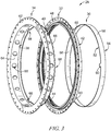
Fig. 3 is an exploded view of the turbine shroud ofFig. 1 showing that the turbine includes, from right to left, a full hoop blade track arranged around a central axis of the engine, a turbine case arranged to extend around the blade track, and a forward case configured to couple to the turbine case and locate the blade track axially relative to the turbine case; -
Fig. 4 is a cross-sectional view of the turbine ofFig. 2 showing that the forward case is coupled to the turbine case and that the forward case interlocks with a leading edge of the blade track to locate the blade track axially and circumferentially while allowing radial movement between the blade track and the turbine case; and -
Fig. 5 is a cross-section view of another embodiment of a turbine shroud for use in the gas turbine engine ofFig. 1 . - For the purposes of promoting an understanding of the principles of the disclosure, reference will now be made to a number of illustrative embodiments illustrated in the drawings and specific language will be used to describe the same.
- An illustrative
gas turbine engine 10 includes anoutput shaft 12, acompressor 14, acombustor 16, and aturbine 18 as shown inFig. 1 . Theoutput shaft 12 is configured to drive a propeller, fan, or gearbox and is powered by theturbine 18. Thecompressor 14 compresses and delivers air to thecombustor 16. Thecombustor 16 mixes fuel with the compressed air received from thecompressor 14 and ignites the fuel. Hot combustion products of the combustion reaction in thecombustor 16 are directed into theturbine 18 and theturbine 18 extracts work to drive thecompressor 14 and theoutput shaft 12. - The
turbine 18 includes a rotatingturbine wheel assembly 20, a staticturbine vane assembly 22, and aturbine shroud 28 as shown inFigs. 1 and 2 . The rotatingturbine wheel assembly 20 is pushed by the hot high-pressure combustion products formed in thecombustor 16 to cause the rotatingturbine wheel assembly 20 to rotate about acentral axis 26 of theengine 10; thereby driving thecompressor 14 and theoutput shaft 12. Thevane assembly 22 is configured to direct the combustion products into another turbine wheel assembly located downstream of thevane assembly 22. Theturbine shroud 28 is arranged around the rotatingturbine wheel assembly 20 to define a gas path for the combustion products. - The
illustrative turbine shroud 28 includes ablade track 30, asupport assembly 32 arranged around theblade track 30, and aforward case 34 as shown inFigs. 3 and4 . Theblade track 30 is arranged aroundblades 36 included in the rotatingturbine wheel assembly 20 to block combustion products from passing over theblades 36. Thesupport assembly 32 is arranged to support theblade track 30 about thecentral axis 26. Theforward case 34 interlocks with theblade track 30 to locate theblade track 30 relative to thesupport assembly 32 by blocking axial and circumferential movement of theblade track 30 relative to thesupport assembly 32 while allowing radial growth between theblade track 30 and thesupport assembly 32 as suggested inFig. 4 . - In the illustrative embodiment, the
forward case 34 includes alocator flange 38 that interlocks with theblade track 30 and anaxial runner 40 that couples theforward case 34 to thesupport assembly 32 as shown inFigs. 2-4 . Thelocator flange 38 extends radially inwardly toward thecentral axis 26 and is formed to include a plurality of radially outwardly extendingcutouts 68 as shown inFig. 3 . Thelocator flange 38 includes an outer radial end coupled to theaxial runner 34 and an inner radial end spaced apart radially from the outer radial end. Thecutouts 68 extend radially outwardly into the inner radial end of thelocator flange 38 toward the outer radial end. - Each
cutout 68 receives a correspondingtang 60 formed in aleading edge 52 of theblade track 30 as shown inFig. 4 . Thelocator flange 38 is configured to contact thetangs 60 and the leadingedge 52 of theblade track 30 to block axial forward movement and circumferential movement of theblade track 30 relative to thesupport assembly 32 while allowing theblade track 30 to move radially in and out in thecutouts 68 to allow for radial thermal-growth. - The
support assembly 32 illustratively includes acarrier 42, aturbine case 44, and thevane assembly 22 as shown inFig. 4 . Thecarrier 42 is an annular, round metallic component that is configured to support theblade track 30 in position adjacent theblades 36 of theturbine wheel assembly 20. Theturbine case 44 extends around thecarrier 42 and supports thecarrier 42 and theblade track 30 relative to thecentral axis 26. Thevane assembly 22 is arranged to position theblade track 30 axially relative to other static turbine components in theturbine 18. - The
turbine case 44 includes a case body 46, aforward mount 48, and anaft mount 50 as shown inFigs. 3 and4 . The case body 46 extends axially along thecentral axis 26 and is formed to include pin receivers arranged to receive a plurality of cross-key pins 94. Theforward mount 48 is coupled to the case body 46 and extends radially outwardly away from the case body 46 as shown inFig. 2 . Theaft mount 50 is spaced apart axially from theforward mount 48 and extends radially inwardly toward thecentral axis 26. In the illustrative embodiment, theforward mount 48 is formed to include a plurality of holes sized to receive fasteners to couple theforward mount 48 to theforward case 34. In some embodiments, theaft mount 50 is discontinuous. For example, in some embodiments, theaft mount 50 includes radially extending scallops as suggested inFig. 5 . - The
illustrative blade track 30 is concentric with and nested into thesupport assembly 32 along thecentral axis 26 of theengine 10 as shown inFig. 4 . In the illustrative embodiment, theblade track 30 is a unitary component forming a full hoop. Theblade track 30 is a component of one-piece, continuous construction, rather than as a series of joined segments. This construction eliminates gaps that may be formed between parts of a multi-piece (or segmented) blade track. In the illustrative embodiment, theblade track 30 comprises ceramic matrix composite materials. - The
blade track 30 includes aleading edge 52, a trailingedge 54, a radialouter surface 56, and a radialinner surface 58 as shown inFig. 4 . The leadingedge 52 is located toward a forward end of thegas turbine engine 10. The trailingedge 54 is axially spaced apart from the leadingedge 52 toward an aft end of theengine 10. The radialouter surface 56 extends between theleading edge 52 and the trailingedge 54. The radialinner surface 58 is radially spaced apart from the radialouter surface 56 to locate the radialinner surface 58 radially between the radialouter surface 56 and thecentral axis 26. - Illustratively, the leading
edge 52 of theblade track 30 is formed to include a plurality oftangs 60 as shown inFigs. 3 and4 . Thetangs 60 extend axially forward away from the trailingedge 54 toward theforward case 34. Thetangs 60 extend through theforward case 34 to interlock theblade track 30 with theforward case 34 as suggested inFig. 4 . - The
forward case 34 includes theaxial runner 40 and thelocator flange 38 as shown inFigs. 3 and4 . Theaxial runner 40 extends axially between a first and second end of theforward case 34 as shown inFigs. 3 and4 . Theaxial runner 40 is coupled to theforward mount 48 and the aft mount 50 of theturbine case 44. Thelocator flange 38 interlocks with thetangs 60 of theblade track 30 to block relative circumferential and axial movement between the blade track and thesupport assembly 32. - The
axial runner 40 includes amount flange 62, aband 64, and ashoulder 66. Theband 64 extends axially between the first and second ends of theforward case 34 and radially about thecentral axis 26. Themount flange 62 extends radially outwardly away from theband 64 and couples to theforward mount 48 of theturbine case 44. Illustratively, fasteners extend through themount flange 62 and theforward mount 48 of theturbine case 44 to couple theforward case 34 to theturbine case 44 as shown inFig. 2 . Theshoulder 66 is spaced axially apart from themount flange 62 and engages a radialinner surface 84 of theaft mount 50 of theturbine case 44. - Illustratively, the
band 64 is arranged to flex/plastically deform in response to being coupled to theturbine case 44 at the forward and aft ends of theforward case 34. For example, theband 64 may flex if a distance between themount flange 62 and theshoulder 66 is greater than a distance between the forward and aft mounts 48, 50 of theturbine case 44. As such, the position of thelocator flange 38 may be adjusted axially along thecentral axis 26 relative to theturbine case 44 and theblade track 30 for a range of forward case lengths. - In the illustrative embodiment, the
band 64 is formed to include a plurality ofapertures 88 as shown inFig. 3 . Theapertures 88 allow air to flow through theforward case 34. Theapertures 88 may help theband 64 flex/plastically deform. Theapertures 88 extend radially through theband 64 and are arranged circumferentially about thecentral axis 26. In the illustrative embodiment, theapertures 88 are axially aligned with one another. - The
shoulder 66 extends radially outwardly away from theband 64 and is press-fitted to the aft mount 50 of theturbine case 44 to couple theforward case 34 to theturbine case 44. As such, an outer diameter of theshoulder 66 is greater than an inner diameter of theturbine case 44 at theaft mount 50. By press-fitting theshoulder 66 to theturbine case 44, the axial position of thelocator flange 38 can be adjusted to position thelocator flange 38 relative to theturbine case 44 to locate theblade track 30 in a desired axial position. - Illustratively, the
shoulder 66 is discontinuous to allow airflow between theshoulder 66 and theturbine case 44. Theshoulder 66 is scalloped in the illustrative embodiment. Thediscontinuous shoulder 66 may help avoid high press-fit stresses while maintaining contact with theturbine case 44 throughout the temperatures of the operating envelope of thegas turbine engine 10. - The
locator flange 38 is coupled to theband 64 of theaxial runner 40 as shown inFig. 4 . Thelocator flange 38 extends radially inwardly away from theturbine case 44 toward thecentral axis 26. Thelocator flange 38 is formed to include a plurality ofcutouts 68 that extend radially outwardly into thelocator flange 38. Eachcutout 68 receives a correspondingtang 60 of theblade track 30 so that the leadingedge 52 of the blade track is adjacent or engaged with thelocator flange 38 as shown inFig. 4 . As such, thelocator flange 38 blocks forward axial movement of theblade track 30 relative to thesupport assembly 32. Thetangs 60 are interlocked with thelocator flange 38 so that thelocator flange 38 blocks circumferential rotation of theblade track 30 relative to thesupport assembly 32. - The
cutouts 68 are sized to allow for radial growth of theblade track 30 as suggested inFig. 4 . For example, theblade track 30 may grow radially outwardly relative to thesupport assembly 32 due to the heat of theturbine 18 to cause thetangs 60 to move radially outwardly in thecutouts 68. As another example, thesupport assembly 32 and theforward case 34 may grow radially outwardly relative to theblade track 30 due to the heat of theturbine 18. As yet another example, theblade track 30 may be cooled using cooling air to cause theblade track 30 to shrink radially inwardly to reduce a clearance gap between the radialinner surface 58 of theblade track 30 and the tips of theblades 36. - In the illustrative embodiment, the
locator flange 38 includes threecutouts 68 and theblade track 30 includes threetangs 60. In other embodiments, thelocator flange 38 and theblade track 30 may include more or less than threecutouts 68 andtangs 60 respectively. - Alternative locating features used with some turbine shrouds include blade tracks with clocking features that extend radially outwardly away from the radial outer surface of the blade track. The clocking features may interlock with the support assembly to block circumferential movement of the blade track. Such clocking features may cause the blade track to be relatively thick or to have a buildup of material on the radial outer side. As a result, such blade tracks may be heavier, may be difficult to manufacture within tolerances, and may have reduced thermal properties as compared to the
blade track 30 of the present disclosure. For example, the additional material may cause alternative blade tracks to respond slowly to cooling air so that tip clearance performance is reduced. - Because the
forward case 34 interlocks with the leadingedge 52 of theblade track 30, theblade track 30 may be located relative to thesupport assembly 32 without radially extending clocking features. As a result, theblade track 30 may have a relatively thin and uniform thickness between the radialouter surface 56 and the radialinner surface 58 of theblade track 30 as suggested inFig. 4 . The relatively thinblack track 30 may respond relatively quickly to cooling air to allow for greater tip clearance control. The illustrative radialouter surface 56 of theblade track 30 is generally cylindrical without protrusions or depressions. For example, alternative blade tracks 30 may include alignment features such as protrusions or depressions. - In illustrative embodiments, the one-piece full hoop of the
blade track 30 encourages uniform radial expansion of theblade track 30 at high temperatures. Uniform radial expansion of theblade track 30 allows theblade track 30 to remain round at high temperatures which results in the ability to further maintain a small gap between theblades 36 and theblade track 30 while hot combustion products are being directed over theblades 36 and theblade track 30. - The
blade track 30 is illustratively made from a ceramic material; and, more particularly, a ceramic matrix composite (CMC) including silicon carbide fibers and silicon carbide matrix. Theblade track 30 has a relatively low coefficient of thermal expansion because of its composition. Considering the relatively small coefficient of thermal expansion, theblade track 30 can be designed to maintain a small gap between theblade track 30 and theblades 36 thereby improving performance of theengine 10. - In the illustrative embodiment, the
carrier 42 includes aforward support 76, anaft support 78, and animpingement plate 80 as shown inFig. 4 . Theforward support 76 is configured to conduct cooling air toward the leadingedge 52 of theblade track 30. Theaft support 78 is formed to include a plurality of apertures and each aperture is configured to receive across-key pin 94 that extends through theturbine case 44 into theaft support 78 as shown inFig. 4 . The cross-key pins 94 locate thecarrier 42 axially and circumferentially relative to thecentral axis 26 and conduct pressurized air into thecarrier 42. In the illustrative embodiment, the forward and aft supports 76, 78 include piston ring seals 92 positioned between thecarrier 42 and the radialouter surface 56 of theblade track 30. - The forward and aft supports 76, 78 cooperate to define a
thermal management chamber 82 that is configured to receive cooling air such as, for example, pressurized air from thecompressor 14. Theimpingement plate 80 extends between the forward and aft supports 76, 78 to partition thethermal management chamber 82 into a radialouter distribution cavity 96 and a radialinner cooling cavity 98. - Pressurized air is conducted through the
cross-key pins 94 in theturbine case 44 into thedistribution cavity 96 as suggested inFig. 4 . Thedistribution cavity 96 is configured to distribute the pressurized air circumferentially around thecentral axis 26 to cause the air in thethermal management chamber 82 to have a generally uniform pressure. Theimpingement plate 80 is formed to include a plurality of holes arranged to direct the pressurized air out of thedistribution cavity 96 into thecooling cavity 98 toward a radialouter surface 56 of theblade track 30 to cool theblade track 30. - In some embodiments, the forward and aft supports 76, 78 are formed to include slots that extend axially into the
supports central axis 26 as shown inFig. 4 . The slots are arranged to receive theimpingement plate 80. In some embodiments, the forward and aft supports 76, 78 are formed to include cutouts that extend circumferentially about thecentral axis 26. The cutouts are arranged to receive theimpingement plate 80 as shown inFig. 5 . In some embodiments, theimpingement plate 80 is brazed to one or more of the forward and aft supports 76, 78. - The
vane assembly 22 is positioned aft of theblade track 30 and engages theblade track 30 to block axial aft movement of theblade track 30 relative to thecarrier 42 and theturbine case 44 as shown inFig. 4 . Theillustrative vane assembly 22 includes an airfoil shaped body configured to receive air from theblades 36 of therotating wheel assembly 20 and to direct the air into another set of blades located downstream of thevane assembly 22. - The
illustrative turbine 18 further includes nozzle guide vanes 86 (sometimes called NGV 86) adapted to engage theforward case 30 as shown inFig. 4 . Thenozzle guide vanes 86 may be adapted to direct the combustion products into theturbine blades 36 at a desired angle and to regulate flow through thevanes 86. Illustratively, thenozzle guide vanes 86 transmit axial loads through theforward case 30 so that theforward case 30 carries the axial loads of thenozzle guide vane 86. As a result, axial loads from thenozzle guide vane 86 acting on theblade track 30 are reduced or eliminated to allow theblade track 30 to be free to move radially inwardly and outwardly relative to the turbine case 46. In the illustrative embodiment, theblade track 30 is axially spaced apart from the nozzle guide vanes 86. - Another
illustrative turbine shroud 128 adapted for use in a gas turbine engine is shown inFig. 5 . Theturbine shroud 128 is substantially similar to theturbine shroud 28 shown inFigs. 1-4 and described herein. Accordingly, similar reference numbers in the 100 series indicate features that are common between theturbine shroud 28 and theturbine shroud 128. The description of theturbine shroud 28 is hereby incorporated by reference to apply to theturbine shroud 128, except in instances when it conflicts with the specific description and drawings of theturbine shroud 128. - The
aft mount 150 of theturbine case 144 is discontinuous to allow airflow between theturbine case 144 and theforward case 134 as shown inFig. 5 . Illustratively, theaft mount 150 is scalloped. - The
forward support 176 and theaft support 178 are formed to include cutouts that extend radially into the forward andaft supports impingement plate 180. In some embodiments, theimpingement plate 180 is brazed with the forward andaft supports carrier 132. The forward andaft supports carrier 132 and the radialouter surface 156 of theblade track 130. - Some gas turbine engines include metallic blade tracks. A relatively large amount of cooling may be needed to maintain structural properties of the metallic blade tracks such as, for example, as the overall pressure ratio and gas path temperatures increase. The metallic blade track may be replaced with a ceramic matrix composite blade track and the apparatus and methods for retaining the ceramic matrix composite blade track as disclosed herein. As an example, the
forward case 34 locates on theturbine case 44 and provides a cross-key feature with the leadingedge 52 of theblade track 30. - The
forward case 34 may improve engine cycle with less cooling air extracted from thecompressor 14. Theforward case 34 avoids cross-key pockets formed in theblade track 30 which may cause stress risers and may make the blade track relatively thicker and more difficult to cool. Relatively thin ceramic matrix composite blade tracks may be easier to manufacture to tolerance. - In one embodiment, a turbine assembly includes the
turbine case 44, thecarrier 42, theblade track 30, and theforward case 34 as shown inFig. 4 . Theblade track 30 is attached to theforward case 34 through a series of cross-keys. In the illustrative embodiment, theblade track 30 is pressure loaded aft and rests against the downstreamturbine vane assembly 22. Theblade track 30 is allowed to float radially in and out as temperatures in theturbine 18 increase and decrease. The fabrication of theblade track 30 may be relatively simple as theblade track 30 is fabricated as a simple ring. A series of machinedtangs 60 protrude from the forward end of theblade track 30. Thetangs 60 are captured by a series of intermittent tangs protruding from the inner diameter of theforward case 34. - The
carrier 42 includes theforward support 76, theaft support 78, and theimpingement plate 80. Theimpingement plate 80 is captured between theaft support 78 and theforward support 76 of thecarrier 42. In some embodiments, a braze joint exists between theforward support 76 and theaft support 78. In some embodiments, theimpingement plate 80 may be brazed at either end or at both ends to theaft support 78 and/or to theforward support 76. - Illustratively, the
carrier 42 is retained through a series ofcross-key pins 94 that protrude through theturbine case 44 and into the aft support. The cross-key pins 94 are threaded into theturbine case 44 in the illustrative embodiment and include a passage that allows for an air fitting to be installed. The air fitting allows high pressure bleed air to be routed into thechamber 82, through theimpingement plate 80, and onto the radialouter surface 56 of theblade track 30. - In other embodiments, the
impingement plate 80 is reconfigured to account for the ease of assembly ofE-seals 192. The E-seal 192 is installed into theaft support 78 prior to pressing of theimpingement plate 80 into the assembly. Additional E-seals 192 may be installed into theforward support 76 prior to installation of theforward support 76 onto the aft support/impingement plate assembly. In some embodiments, piston ring type seals 92 are used in place ofE-seals 192. In some embodiments, the piston ring seals 92 are made of ceramic matrix composite material. - The present disclosure provides a forward case 34(sometimes called a forward support 34) that carries nozzle guide vane load provides cross-keying near the leading edge of the
blade track 30. Illustratively, theforward support 34 is located via a press fit to theturbine case 44 radially outboard of the cross-key feature. In some embodiments, one of theturbine case 44,forward support 34, or both includes a discontinuous press-fit diameter to avoid high press-fit strain while maintaining contact throughout a temperature range of the entire operating envelope. The discontinuous interface may be used to allow air to flow across the cross-key flange of theforward support 34 from one side to the other. - In some embodiments, the
forward support 34 is formed to include relativelylarge holes 88 in the forward caseaxial runner 40 for structural and flow system reasons. The holes may provide flexibility for the cross-key flange to follow the centerline of theturbine case 44. Theholes 88 may reduce weight and the holes may allow air to flow from one side of the forward support to the other to enable an air-system. - The cross-keying may avoid back side geometry on the
blade track 30 such as, for example, radial cross-key counter bores which may have a negative effect on thermal management and tip clearance control. The cross-key feature may allow for thinner ceramic matrix composite blade tracks due to the elimination of pin cross-key counter bores on the back side of the blade track. Thinner blade tracks may be used to optimize the engine. For example, thermal response could be traded with weight which could be traded with thermal gradients and thermal stresses. A thinner blade track may be easier to produce without out of round issues. - The turbine assembly may provide good alignment between the turbine case centerline and the blade track centerline to minimize tip clearance stack ups. The discontinuous press-fit between the forward support and the turbine case may reduce stresses, allow for more differential thermal growth, and would allow for air to pass to the cavity above the carrier. The relatively large holes in the forward case axial runner may allow compressor discharge air to pass to the outer cavities for reduced stress on the forward support and for failure mode management of the seal segment. These holes may reduce the stiffness with respect to differential thermal growth between the front mounting flange and the management of the seal segment. The holes may reduce the stiffness with respect to differential thermal growth between the front mounting flange and the cross-key flange.
- While the disclosure has been illustrated and described in detail in the foregoing drawings and description, the same is to be considered as exemplary and not restrictive in character, it being understood that only illustrative embodiments thereof have been shown and described and that all changes and modifications that come within the spirit of the disclosure are desired to be protected.
Claims (15)
- A turbine shroud (28) assembly for a gas turbine engine (10), the turbine shroud (28) assembly comprising
an annular turbine case (44) arranged around a central axis (26) of the turbine shroud assembly,
a blade track (30) comprising ceramic matrix composite materials located radially between the turbine case (44) and the central axis (26), the blade track (30) having a leading edge and a trailing edge axially spaced apart from the leading edge, and
a forward case (34) coupled to the turbine case (44) and arranged to extend radially inwardly away from the turbine case (44) toward the central axis (26) and interlocked with the leading edge of the blade track (30) to block circumferential and axial movement of the blade track (30) relative to the turbine case while allowing radial movement of the blade track relative to the turbine case. - The turbine shroud assembly of claim 1, wherein the forward case (34) includes an axial runner (40) that extends from a first end to a second end axially spaced from the first end and a locator flange (38) coupled to the axial runner (40) toward the second end, the locator flange (38) extends radially inwardly away from the turbine case (44) toward the central axis (26), and the locator flange (38) interlocks with the leading edge of the blade track (30).
- The turbine shroud assembly of claim 2, wherein the locator flange (38) is formed to include a plurality of cutouts (68) that extend radially outwardly into the locator flange (38), the leading edge of the blade track (30) is formed to include a plurality of tangs (60) that extend axially forward away from the trailing edge of the blade track (30) toward the locator flange (38), and each tang (60) is received by one of the cutouts (68) formed in the locator flange (38) of the forward case (34) to interlock the forward case (34) and the blade track (30).
- The turbine shroud assembly of any of claims 1 to 3, wherein the blade track (30) includes a radial outer surface that faces the turbine case (44) and a radial inner surface radially spaced apart from the radial outer surface and the radial outer surface of the blade track (30) is generally cylindrical without protrusions and depressions.
- The turbine shroud assembly of claim 3, wherein the locator flange (38) is formed to include at least three cutouts (68) and the leading edge of the blade track (30) is formed to include at least three tangs (60).
- The turbine shroud assembly of any of claims 2 to 5, wherein the axial runner (40) is formed to define a plurality of apertures (88) that extends radially through the axial runner (40).
- The turbine shroud assembly of claim 1, wherein the forward case (34) includes a first end, a second end axially spaced apart from the first end, an axial runner (40) that extends between the first and second ends, and a locator flange (38) that extends radially inwardly away from the axial runner (40) toward the central axis (26), the axial runner (40) includes a band (64) that extends between the first and second ends of the forward case (34), a mount flange (62) that extends radially outwardly away from the band (64) at the first end of the forward case, and a shoulder (66) that extends radially outwardly away from the band (64) at the second end of the forward case (34).
- The turbine shroud assembly of claim 7, wherein the turbine case (44) includes a forward mount (48) and an aft mount (50) spaced apart axially from the forward mount (48), the aft mount (50) includes a radial inner surface that faces the central axis (26), and the shoulder (66) of the axial runner (40) has an outer diameter that is larger than an inner diameter of the radial inner surface of the aft mount (50).
- The turbine shroud assembly of claim 7 or claim 8, wherein the shoulder (66) is formed to include radially extending scallops arranged to allow air flow between the shoulder (66) and the turbine case (44).
- The turbine shroud assembly of claim 1, further comprising a carrier located radially between the turbine case and the blade track and a hollow cross-key pin (94) that extends through the turbine case (44) into the carrier (42), the carrier (42) is arranged to define an inwardly facing thermal management chamber (82), and the hollow cross-key pin (94) is configured to direct airflow through the turbine case (44) and the carrier (82) into the thermal management chamber (82) toward the blade track (30).
- A turbine shroud assembly for a gas turbine engine as claimed in any of claims 1 to 10, the assembly further comprising
a vane assembly (22) located radially between the turbine case (44) and the central axis (26) and located axially aft of the blade track (30), the vane assembly (22) arranged to engage the trailing edge of the blade track (30) to block axially aft movement of the blade track (30) relative to the turbine case (44). - The turbine assembly of claim 11, further comprising nozzle guide vanes (86) located radially between the turbine case (44) and the central axis (26) and located axially forward of the blade track (30) and the nozzle guide vanes (86) engage the forward case (34) to transmit axial loads through the forward case (34).
- The turbine assembly of claim any of claims 7-9 or 11, wherein the shoulder (66) is discontinuous.
- A method of assembling a turbine assembly for use in a gas turbine engine, the method comprising
providing an annular turbine case (44) arranged around a central axis (26) of the turbine case (44), a full hoop blade track (30) having a leading edge and a trailing edge axially spaced apart from the leading edge, and a forward case (34) having an axially extending axial runner (40) and a radially inwardly extending locator flange (38),
fastening the axial runner (40) of the forward case (34) to the turbine case (44), and
interlocking the leading edge of a blade track (30) with the locator flange (38) of the forward case (34) and optionally further comprising press-fitting the axial runner (40) of the forward case (34) to the turbine case (44). - The method of claim 14, wherein the locator flange (38) is formed to include a cutout (68) and the leading edge of the blade track (30) is formed to include a tang (60) that extends axially away from the trailing edge of the blade track (30) toward the forward case (34) and the step of interlocking the leading edge of the blade track (30) with the locator flange (38) of the forward case (34) includes the steps of aligning circumferentially the tang (60) of the blade track (30) with the cutout (68) formed in the locator flange (38) and moving the blade track (30) axially toward the locator flange (38) to cause the cutout (68) to receive the tang (60).
Applications Claiming Priority (2)
| Application Number | Priority Date | Filing Date | Title |
|---|---|---|---|
| US15/163,079 US10287906B2 (en) | 2016-05-24 | 2016-05-24 | Turbine shroud with full hoop ceramic matrix composite blade track and seal system |
| US15/217,305 US10415415B2 (en) | 2016-07-22 | 2016-07-22 | Turbine shroud with forward case and full hoop blade track |
Publications (1)
| Publication Number | Publication Date |
|---|---|
| EP3249166A1 true EP3249166A1 (en) | 2017-11-29 |
Family
ID=58606183
Family Applications (2)
| Application Number | Title | Priority Date | Filing Date |
|---|---|---|---|
| EP17167778.4A Not-in-force EP3312392B1 (en) | 2016-05-24 | 2017-04-24 | Turbine shroud and seal system |
| EP17167781.8A Withdrawn EP3249166A1 (en) | 2016-05-24 | 2017-04-24 | Turbine shroud |
Family Applications Before (1)
| Application Number | Title | Priority Date | Filing Date |
|---|---|---|---|
| EP17167778.4A Not-in-force EP3312392B1 (en) | 2016-05-24 | 2017-04-24 | Turbine shroud and seal system |
Country Status (1)
| Country | Link |
|---|---|
| EP (2) | EP3312392B1 (en) |
Cited By (1)
| Publication number | Priority date | Publication date | Assignee | Title |
|---|---|---|---|---|
| CN111630252A (en) * | 2018-01-09 | 2020-09-04 | 赛峰航空器发动机 | Turbine shroud assembly |
Citations (5)
| Publication number | Priority date | Publication date | Assignee | Title |
|---|---|---|---|---|
| EP2299061A2 (en) * | 2009-09-01 | 2011-03-23 | United Technologies Corporation | Ceramic turbine shroud support |
| FR2980235A1 (en) * | 2011-09-20 | 2013-03-22 | Snecma | Low pressure turbine for use in e.g. turboprop engine of aircraft, has ring radially guided on turbine casing such that casing is deformed freely in radial direction, by thermal dilation, without forcing ring to deform radially |
| EP2690257A2 (en) * | 2012-07-23 | 2014-01-29 | Rolls-Royce plc | Fastener |
| WO2014120334A1 (en) * | 2013-01-29 | 2014-08-07 | Sippel Aaron D | Turbine shroud |
| US20140271144A1 (en) * | 2013-03-13 | 2014-09-18 | Rolls-Royce North American Technologies, Inc. | Turbine shroud |
Family Cites Families (3)
| Publication number | Priority date | Publication date | Assignee | Title |
|---|---|---|---|---|
| US6942445B2 (en) * | 2003-12-04 | 2005-09-13 | Honeywell International Inc. | Gas turbine cooled shroud assembly with hot gas ingestion suppression |
| GB201308605D0 (en) * | 2013-05-14 | 2013-06-19 | Rolls Royce Plc | A shroud arrangement for a gas turbine engine |
| GB201308602D0 (en) * | 2013-05-14 | 2013-06-19 | Rolls Royce Plc | A Shroud Arrangement for a Gas Turbine Engine |
-
2017
- 2017-04-24 EP EP17167778.4A patent/EP3312392B1/en not_active Not-in-force
- 2017-04-24 EP EP17167781.8A patent/EP3249166A1/en not_active Withdrawn
Patent Citations (5)
| Publication number | Priority date | Publication date | Assignee | Title |
|---|---|---|---|---|
| EP2299061A2 (en) * | 2009-09-01 | 2011-03-23 | United Technologies Corporation | Ceramic turbine shroud support |
| FR2980235A1 (en) * | 2011-09-20 | 2013-03-22 | Snecma | Low pressure turbine for use in e.g. turboprop engine of aircraft, has ring radially guided on turbine casing such that casing is deformed freely in radial direction, by thermal dilation, without forcing ring to deform radially |
| EP2690257A2 (en) * | 2012-07-23 | 2014-01-29 | Rolls-Royce plc | Fastener |
| WO2014120334A1 (en) * | 2013-01-29 | 2014-08-07 | Sippel Aaron D | Turbine shroud |
| US20140271144A1 (en) * | 2013-03-13 | 2014-09-18 | Rolls-Royce North American Technologies, Inc. | Turbine shroud |
Cited By (2)
| Publication number | Priority date | Publication date | Assignee | Title |
|---|---|---|---|---|
| CN111630252A (en) * | 2018-01-09 | 2020-09-04 | 赛峰航空器发动机 | Turbine shroud assembly |
| CN111630252B (en) * | 2018-01-09 | 2023-01-17 | 赛峰航空器发动机 | Turbine shroud assembly |
Also Published As
| Publication number | Publication date |
|---|---|
| EP3312392A1 (en) | 2018-04-25 |
| EP3312392B1 (en) | 2019-03-27 |
Similar Documents
| Publication | Publication Date | Title |
|---|---|---|
| US10995627B2 (en) | Turbine shroud with forward case and full hoop blade track | |
| US9752592B2 (en) | Turbine shroud | |
| US10605121B2 (en) | Mounted ceramic matrix composite component with clamped flange attachment | |
| EP3037628B1 (en) | Turbine shroud | |
| EP3088690B1 (en) | Full hoop blade track with flanged segments | |
| US9810086B2 (en) | Asymmetric radial spline seal for a gas turbine engine | |
| US20150044049A1 (en) | Dovetail retention system for blade tracks | |
| EP3670843B1 (en) | Turbine section of a gas turbine engine with ceramic matrix composite vanes | |
| US20210189909A1 (en) | Turbine shroud assembly with case captured seal segment carrier | |
| US11326474B2 (en) | Turbine shroud assembly with pinned attachment supplements for ceramic matrix composite component mounting | |
| US11215080B1 (en) | Turbine shroud assembly with integrated ceramic matrix composite component support pins | |
| US11053817B2 (en) | Turbine shroud assembly with ceramic matrix composite blade track segments and full hoop carrier | |
| US11215075B2 (en) | Turbine shroud assembly with flange mounted ceramic matrix composite turbine shroud ring | |
| EP1217231B1 (en) | Bolted joint for rotor disks and method of reducing thermal gradients therein | |
| EP3249166A1 (en) | Turbine shroud | |
| US10370985B2 (en) | Full hoop blade track with axially keyed features | |
| US11959389B2 (en) | Turbine shroud segments with angular locating feature | |
| US11840936B1 (en) | Ceramic matrix composite blade track segment with pin-locating shim kit | |
| US11713694B1 (en) | Ceramic matrix composite blade track segment with two-piece carrier | |
| US11885225B1 (en) | Turbine blade track with ceramic matrix composite segments having attachment flange draft angles | |
| US20220397041A1 (en) | Turbine shroud segments with angular locating feature | |
| US11879362B1 (en) | Segmented ceramic matrix composite vane endwall integration with turbine shroud ring and mounting thereof | |
| US11732604B1 (en) | Ceramic matrix composite blade track segment with integrated cooling passages | |
| US11208911B2 (en) | Turbine shroud ring segments with ceramic matrix composite components | |
| US10787916B2 (en) | Turbine wheel assembly with ceramic matrix composite components |
Legal Events
| Date | Code | Title | Description |
|---|---|---|---|
| PUAI | Public reference made under article 153(3) epc to a published international application that has entered the european phase |
Free format text: ORIGINAL CODE: 0009012 |
|
| AK | Designated contracting states |
Kind code of ref document: A1 Designated state(s): AL AT BE BG CH CY CZ DE DK EE ES FI FR GB GR HR HU IE IS IT LI LT LU LV MC MK MT NL NO PL PT RO RS SE SI SK SM TR |
|
| AX | Request for extension of the european patent |
Extension state: BA ME |
|
| STAA | Information on the status of an ep patent application or granted ep patent |
Free format text: STATUS: REQUEST FOR EXAMINATION WAS MADE |
|
| 17P | Request for examination filed |
Effective date: 20180524 |
|
| RBV | Designated contracting states (corrected) |
Designated state(s): AL AT BE BG CH CY CZ DE DK EE ES FI FR GB GR HR HU IE IS IT LI LT LU LV MC MK MT NL NO PL PT RO RS SE SI SK SM TR |
|
| STAA | Information on the status of an ep patent application or granted ep patent |
Free format text: STATUS: THE APPLICATION IS DEEMED TO BE WITHDRAWN |
|
| 18D | Application deemed to be withdrawn |
Effective date: 20201103 |