WO2024180866A1 - 描画装置および描画方法 - Google Patents
描画装置および描画方法 Download PDFInfo
- Publication number
- WO2024180866A1 WO2024180866A1 PCT/JP2023/044760 JP2023044760W WO2024180866A1 WO 2024180866 A1 WO2024180866 A1 WO 2024180866A1 JP 2023044760 W JP2023044760 W JP 2023044760W WO 2024180866 A1 WO2024180866 A1 WO 2024180866A1
- Authority
- WO
- WIPO (PCT)
- Prior art keywords
- stage
- scanning direction
- sub
- movement
- reading
- Prior art date
- Legal status (The legal status is an assumption and is not a legal conclusion. Google has not performed a legal analysis and makes no representation as to the accuracy of the status listed.)
- Ceased
Links
Images


Classifications
-
- G—PHYSICS
- G03—PHOTOGRAPHY; CINEMATOGRAPHY; ANALOGOUS TECHNIQUES USING WAVES OTHER THAN OPTICAL WAVES; ELECTROGRAPHY; HOLOGRAPHY
- G03F—PHOTOMECHANICAL PRODUCTION OF TEXTURED OR PATTERNED SURFACES, e.g. FOR PRINTING, FOR PROCESSING OF SEMICONDUCTOR DEVICES; MATERIALS THEREFOR; ORIGINALS THEREFOR; APPARATUS SPECIALLY ADAPTED THEREFOR
- G03F7/00—Photomechanical, e.g. photolithographic, production of textured or patterned surfaces, e.g. printing surfaces; Materials therefor, e.g. comprising photoresists; Apparatus specially adapted therefor
- G03F7/70—Microphotolithographic exposure; Apparatus therefor
- G03F7/70691—Handling of masks or workpieces
- G03F7/70775—Position control, e.g. interferometers or encoders for determining the stage position
-
- G—PHYSICS
- G01—MEASURING; TESTING
- G01B—MEASURING LENGTH, THICKNESS OR SIMILAR LINEAR DIMENSIONS; MEASURING ANGLES; MEASURING AREAS; MEASURING IRREGULARITIES OF SURFACES OR CONTOURS
- G01B11/00—Measuring arrangements characterised by the use of optical techniques
-
- G—PHYSICS
- G01—MEASURING; TESTING
- G01B—MEASURING LENGTH, THICKNESS OR SIMILAR LINEAR DIMENSIONS; MEASURING ANGLES; MEASURING AREAS; MEASURING IRREGULARITIES OF SURFACES OR CONTOURS
- G01B11/00—Measuring arrangements characterised by the use of optical techniques
- G01B11/02—Measuring arrangements characterised by the use of optical techniques for measuring length, width or thickness
- G01B11/03—Measuring arrangements characterised by the use of optical techniques for measuring length, width or thickness by measuring coordinates of points
-
- G—PHYSICS
- G03—PHOTOGRAPHY; CINEMATOGRAPHY; ANALOGOUS TECHNIQUES USING WAVES OTHER THAN OPTICAL WAVES; ELECTROGRAPHY; HOLOGRAPHY
- G03F—PHOTOMECHANICAL PRODUCTION OF TEXTURED OR PATTERNED SURFACES, e.g. FOR PRINTING, FOR PROCESSING OF SEMICONDUCTOR DEVICES; MATERIALS THEREFOR; ORIGINALS THEREFOR; APPARATUS SPECIALLY ADAPTED THEREFOR
- G03F7/00—Photomechanical, e.g. photolithographic, production of textured or patterned surfaces, e.g. printing surfaces; Materials therefor, e.g. comprising photoresists; Apparatus specially adapted therefor
- G03F7/20—Exposure; Apparatus therefor
-
- G—PHYSICS
- G03—PHOTOGRAPHY; CINEMATOGRAPHY; ANALOGOUS TECHNIQUES USING WAVES OTHER THAN OPTICAL WAVES; ELECTROGRAPHY; HOLOGRAPHY
- G03F—PHOTOMECHANICAL PRODUCTION OF TEXTURED OR PATTERNED SURFACES, e.g. FOR PRINTING, FOR PROCESSING OF SEMICONDUCTOR DEVICES; MATERIALS THEREFOR; ORIGINALS THEREFOR; APPARATUS SPECIALLY ADAPTED THEREFOR
- G03F7/00—Photomechanical, e.g. photolithographic, production of textured or patterned surfaces, e.g. printing surfaces; Materials therefor, e.g. comprising photoresists; Apparatus specially adapted therefor
- G03F7/70—Microphotolithographic exposure; Apparatus therefor
- G03F7/70216—Mask projection systems
- G03F7/70283—Mask effects on the imaging process
- G03F7/70291—Addressable masks, e.g. spatial light modulators [SLMs], digital micro-mirror devices [DMDs] or liquid crystal display [LCD] patterning devices
-
- G—PHYSICS
- G03—PHOTOGRAPHY; CINEMATOGRAPHY; ANALOGOUS TECHNIQUES USING WAVES OTHER THAN OPTICAL WAVES; ELECTROGRAPHY; HOLOGRAPHY
- G03F—PHOTOMECHANICAL PRODUCTION OF TEXTURED OR PATTERNED SURFACES, e.g. FOR PRINTING, FOR PROCESSING OF SEMICONDUCTOR DEVICES; MATERIALS THEREFOR; ORIGINALS THEREFOR; APPARATUS SPECIALLY ADAPTED THEREFOR
- G03F7/00—Photomechanical, e.g. photolithographic, production of textured or patterned surfaces, e.g. printing surfaces; Materials therefor, e.g. comprising photoresists; Apparatus specially adapted therefor
- G03F7/70—Microphotolithographic exposure; Apparatus therefor
- G03F7/70691—Handling of masks or workpieces
- G03F7/70716—Stages
-
- G—PHYSICS
- G01—MEASURING; TESTING
- G01B—MEASURING LENGTH, THICKNESS OR SIMILAR LINEAR DIMENSIONS; MEASURING ANGLES; MEASURING AREAS; MEASURING IRREGULARITIES OF SURFACES OR CONTOURS
- G01B2210/00—Aspects not specifically covered by any group under G01B, e.g. of wheel alignment, caliper-like sensors
- G01B2210/56—Measuring geometric parameters of semiconductor structures, e.g. profile, critical dimensions or trench depth
Definitions
- This invention relates to a technique for drawing patterns on substrates such as semiconductor substrates, semiconductor package substrates, printed wiring boards, and glass substrates.
- One technique for forming patterns such as wiring patterns on various substrates is to expose a photosensitive layer formed on the surface of the substrate by irradiating the substrate with light according to the pattern to be formed.
- the drawing device described in Patent Document 1 draws a predetermined pattern on the substrate by irradiating the substrate with a light beam modulated according to the pattern to be drawn.
- the drawing device described in Patent Document 2 draws a pattern by irradiating the substrate with exposure illumination light via a reticle corresponding to the pattern shape.
- partial exposure is performed multiple times while changing the position of incidence of light in order to perform imaging on the entire substrate.
- exposure is performed by alternating between main scanning movement, in which the stage on which the substrate is placed is moved in the main scanning direction, and sub-scanning movement, in which the stage is stepped in the sub-scanning direction that intersects with main scanning movement.
- main scanning movement in which the stage on which the substrate is placed is moved in the main scanning direction
- sub-scanning movement in which the stage is stepped in the sub-scanning direction that intersects with main scanning movement.
- One type of scanning movement like this is known as the step-and-repeat method or the step-and-scan method.
- the stage position during scanning movement must be measured accurately.
- the technology described in Patent Document 1 uses a position measurement unit that uses a laser interferometer.
- the stage position is measured by a linear encoder that optically reads a two-dimensional scale formed on the measurement stage.
- the laser interferometer method has been the most widely used so far because of its superior measurement accuracy, resolution, and long-term stability.
- short-term fluctuations in measurement values caused by temperature fluctuations in the atmosphere along the optical path of the laser light have become a major source of error.
- This invention was made in consideration of the above problems, and aims to make it possible to measure the stage position using the principles of a linear encoder in a technology that performs drawing using light while moving a stage on which a substrate is placed, without increasing the size and cost of the device.
- One aspect of the invention is a drawing device that includes a stage on which a substrate can be placed, a drawing unit that irradiates light onto the substrate placed on the stage to draw on it, a first movement mechanism that moves the stage relative to the drawing unit to perform main scanning movement in a main scanning direction that is parallel to the top surface and intersects with each other, and sub-scanning movement in a sub-scanning direction that intersects with the main scanning direction, and a position detection unit that detects the relative position of the drawing unit and the stage in the main scanning direction.
- the position detection unit includes a linear scale that is provided integrally with the stage and has a scale formed along the main scanning direction, a reading head that reads the scale, and a second movement mechanism that moves the reading head in the sub-scanning direction relative to the drawing unit, and when the stage is moved in the sub-scanning direction by the first movement mechanism, the second movement mechanism moves the reading head by an amount corresponding to the amount of movement of the stage.
- the position of the stage in the main scanning direction is detected by the reading head reading the scale (gradations) of a linear scale that extends in the main scanning direction and moves integrally with the stage.
- the position detection unit measures the main scanning direction position of the stage using the measurement principle of the linear encoder method. Meanwhile, when the stage moves in the sub-scanning direction, the reading head is moved in the sub-scanning direction by an amount corresponding to the amount of movement.
- the reading head when the linear scale, which moves integrally with the stage, moves in the sub-scanning direction, the reading head also moves in the sub-scanning direction following this. Therefore, by reading the scale with the reading head after it has moved, it is possible to continue detecting the position of the stage. In this way, according to the present invention, even if the number of movements of the stage in the sub-scanning direction increases, there is no need to increase the number of reading heads installed, and the position of the stage can be detected using a small number of reading heads.
- Another aspect of the invention is a drawing method in which a stage with a substrate placed on its upper surface is moved, and main scanning movement in a main scanning direction that is parallel to the upper surface and intersects with each other, and sub-scanning movement in a sub-scanning direction that intersects with the main scanning direction are alternately performed while irradiating the substrate with light from a drawing unit to draw, in which a reading head detects the relative position of the drawing unit and the stage in the main scanning direction by reading a linear scale that is integral with the stage and has a scale formed along the main scanning direction, and when the stage moves in the sub-scanning direction, the reading head is moved by an amount corresponding to the amount of movement of the stage.
- the reading head when detecting the stage position using a linear encoder consisting of a pair of a linear scale and a reading head, the reading head also moves in the sub-scanning direction in response to the sub-scanning movement of the stage. Therefore, even if the stage moves many times in the sub-scanning direction, position detection is possible using a small number of reading heads, and it is possible to prevent the device from becoming larger and more expensive.
- FIG. 1 is a front view showing a schematic diagram of a first embodiment of a drawing device according to the present invention
- 2 is a block diagram showing an example of an electrical configuration of the exposure apparatus in FIG. 1 .
- FIG. 2 is a view showing the main part of the exposure device as viewed in the Y direction.
- FIG. 2 is a view showing the main part of the exposure device as viewed in the Y direction.
- FIG. 2 is a view showing the main part of the exposure device as viewed in the Y direction.
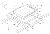
- FIG. 2 is a perspective view showing a schematic configuration of a stage driving mechanism.
- FIG. 13 is a diagram showing an example of a configuration in which two sets of exposure heads are provided.
- FIG. 13 is a diagram showing an example of a configuration in which two sets of exposure heads are provided.
- FIG. 13 is a diagram showing an example of a configuration in which two sets of exposure heads are provided.
- FIG. 13 is a diagram showing an example of a configuration in which two sets of exposure heads are provided.
- 3A to 3C are diagrams illustrating the principle of position detection in a position detection mechanism.
- 3A to 3C are diagrams illustrating the principle of position detection in a position detection mechanism.
- 5 is a flowchart showing the processing content of an exposure operation in this embodiment.
- FIG. 4 is a diagram showing the manner in which a stage and a read head move.
- 13 is a view showing the main part of the exposure apparatus of the second embodiment as viewed in the Y direction.
- 13 is a view showing the main part of the exposure apparatus of the second embodiment as viewed in the Y direction.
- 13 is a view showing the main part of the exposure apparatus of the second embodiment as viewed in the Y direction.
- FIG. 2 is a perspective view showing a schematic configuration of a stage driving mechanism and its surroundings.
- FIG. 1 is a front view showing a schematic configuration of an exposure apparatus as a first embodiment of a drawing apparatus according to the present invention.
- Fig. 2 is a block diagram showing an example of an electrical configuration of the exposure apparatus of Fig. 1.
- the X direction which is a horizontal direction
- the Y direction which is a horizontal direction perpendicular to the X direction
- the Z direction which is a vertical direction
- a rotation direction ⁇ around a rotation axis parallel to the Z direction are appropriately shown.
- the exposure device 1 draws a pattern on a photosensitive material by irradiating a substrate S (substrate to be exposed) on which a layer of photosensitive material such as resist has been formed with laser light of a predetermined pattern.
- a substrate S substrate to be exposed
- various substrates such as semiconductor substrates, semiconductor package substrates, printed wiring substrates, and glass substrates for various display devices can be used.
- the shape is not particularly limited, and for example, a disk-shaped substrate, a rectangular substrate, or an irregular substrate processed into a specific outline can be used as the substrate S.
- the exposure device 1 has a main body 11, which is composed of a main body frame 111 and a cover panel (not shown) attached to the main body frame 111. Various components of the exposure device 1 are arranged both inside and outside the main body 11.
- the inside of the main body 11 of the exposure apparatus 1 is divided into a processing area 112 and a transfer area 113.
- the stage 2 the stage driving mechanism 3, the exposure unit 4, the alignment unit 5, and the position detection mechanism 8 are mainly arranged.
- Each of these parts is arranged on the base part 100, or is attached to a gantry-shaped support frame 101 arranged so as to straddle the base part 100.
- an illumination unit 6 that supplies illumination light to the alignment unit 5 is arranged outside the main body 11.
- a transport device 7 such as a transport robot that transports the substrate S to and from the processing area 112 is arranged.
- a control unit 9 is arranged inside the main body 11. The control unit 9 is electrically connected to each part of the exposure apparatus 1 and controls the operation of each of these parts.
- the transport device 7 arranged in the transfer area 113 inside the main body 11 receives unprocessed substrates S from an external transport device or substrate storage device (not shown) and transports (loads) them into the processing area 112, and also transports (unloads) processed substrates S from the processing area 112 and sends them out to the outside.
- the loading of unprocessed substrates S and the unloading of processed substrates S are performed by the transport device 7 in response to instructions from the control unit 9.
- the stage 2 has a flat plate-like outer shape and holds the substrate S placed on its upper surface in a horizontal position.
- a number of suction holes are formed in the upper surface of the stage 2, and the substrate S placed on the stage 2 is fixed to the upper surface of the stage 2 by applying a negative pressure (suction pressure) to the suction holes.
- the stage 2 is driven by a stage driving mechanism 3.
- the stage driving mechanism 3 is an X-Y-Z- ⁇ driving mechanism that moves the stage 2 in the Y direction (main scanning direction), X direction (sub-scanning direction), Z direction, and rotational direction ⁇ (yaw direction).
- the stage driving mechanism 3 has a Y-axis robot 31, a Y moving table 32, an X-axis robot 33, an X moving table 34, a ⁇ -axis robot 35, and a Z-axis robot 37.
- the Y-axis robot 31 is a single-axis robot that extends in the Y direction.
- the Y moving table is driven in the Y direction by the Y-axis robot 31.
- the X-axis robot 33 is a single-axis robot that extends in the X direction on the upper surface of the Y moving table 32.
- the X moving table 34 is driven in the X direction by the X-axis robot 33.
- the ⁇ -axis robot 35 drives the stage 2, which is supported on the upper surface of the X moving table 34, in the rotational direction ⁇ relative to the X moving table 34.
- the stage driving mechanism 3 can therefore drive the stage 2 in the Y direction by the Y-axis servo motor of the Y-axis robot 31, drive the stage 2 in the X direction by the X-axis servo motor of the X-axis robot 33, and drive the stage 2 in the rotational direction ⁇ by the ⁇ -axis servo motor of the ⁇ -axis robot 35. These servo motors are not shown.
- the stage driving mechanism 3 can also drive the stage 2 in the Z direction by the Z-axis robot 37.
- the stage driving mechanism 3 moves the substrate S placed on the stage 2 by operating the Y-axis robot 31, X-axis robot 33, ⁇ -axis robot 35, and Z-axis robot 37 in response to commands from the control unit 9.
- a position detection mechanism 8 is provided to detect the position of the stage 2 being moved in this manner.
- the position detection mechanism 8 has a linear scale 81 extending in the Y direction on the top surface of the stage 2, and a read head 82 attached to the support frame 101 for reading the scale (gradations) engraved on the linear scale 81; these together form a linear encoder.
- the output of the read head 82 is input to the control unit 9.
- the exposure unit 4 has an exposure head 41 and a light irradiation section 40.
- the exposure head 41 is disposed above the substrate S on the stage 2.
- the light irradiation section 40 includes a light source driving section 42, a laser emission section 43, and an illumination optical system 44, and irradiates the exposure head 41 with laser light.
- a plurality of exposure units 4 may be provided at different positions in the X direction.
- the laser light emitted from the laser emission unit 43 by the operation of the light source drive unit 42 is irradiated to the exposure head 41 via the illumination optical system 44.
- the exposure head 41 modulates the laser light emitted from the light irradiation unit 40 using a spatial light modulator 400 (hereinafter sometimes simply referred to as the "light modulator"), and irradiates it onto the substrate S moving directly below it. In this way, the substrate S is exposed to the laser light beam, and a pattern is drawn on the substrate S (exposure operation).
- the alignment unit 5 has an alignment camera 51 that is placed above the substrate S on the stage 2.
- This alignment camera 51 has a lens barrel, an objective lens, and a CCD image sensor, and captures an image of an alignment mark provided on the top surface of the substrate S that moves directly below it.
- the CCD image sensor provided in the alignment camera 51 is composed of, for example, an area image sensor (two-dimensional image sensor).
- the lighting unit 6 is connected to the lens barrel of the alignment camera 51 via an optical fiber 61, and supplies illumination light to the alignment camera 51.
- the illumination light guided by the optical fiber 61 extending from the lighting unit 6 is guided to the top surface of the substrate S via the lens barrel of the alignment camera 51.
- the light reflected from the substrate S is incident on the CCD image sensor via the objective lens. This results in an image of the top surface of the substrate S being captured.
- the alignment camera 51 is electrically connected to the control unit 9, and captures the captured image in response to instructions from the control unit 9, and transmits this captured image to the control unit 9.
- the control unit 9 realizes various processes by controlling the operation of each unit described above.
- the control unit 9 is equipped with a CPU (Central Processing Unit) 91, memory (RAM) 92, storage 93, input unit 94, display unit 95, interface unit 96, etc.
- the CPU 91 reads out and executes a control program 931 previously stored in the storage 93, and performs various operations described below.
- the memory 92 is used for the calculation processing by the CPU 91, or stores data generated as a result of the calculation processing in the short term.
- the storage 93 stores various data and control programs in the long term.
- the storage 93 is a non-volatile storage device such as a flash memory storage device or a hard disk drive device, and stores, in addition to the control program 931 executed by the CPU 91, for example, CAD (Computer Aided Design) data 932, which is design data representing the contents of the pattern to be drawn.
- CAD Computer Aided Design
- the input unit 94 accepts operational input from the user, and for this purpose has an appropriate input device (not shown), such as a keyboard, mouse, or touch panel.
- the display unit 95 notifies the user by displaying and outputting various information, and for this purpose has an appropriate display device, for example, a liquid crystal display panel.
- the interface unit 96 is responsible for communication with an external device.
- the interface unit 96 functions when the exposure apparatus 1 receives a control program 931 and CAD data 932 from the outside.
- the interface unit 96 may have a configuration (for example, a disk drive) and function for reading data from an external recording medium.
- the CPU 91 executes the control program 931 to implement, in software, functional blocks such as an exposure data generation unit 911, an exposure control unit 912, a focus control unit 913, a stage control unit 914, and a position calculation unit 915. Note that at least a portion of each of these functional blocks may be implemented by dedicated hardware.
- the exposure data generation unit 911 generates exposure data for modulating the light beam according to the pattern, based on the CAD data 932 read from the storage 93. If the substrate S is deformed, such as distorted, the exposure data generation unit 911 corrects the exposure data according to the amount of distortion of the substrate S, making it possible to draw according to the shape of the substrate S.
- the exposure data is sent to the exposure head 41, which modulates the laser light emitted from the light irradiation unit 40 according to the exposure data.
- the modulated light beam thus modulated according to the pattern is irradiated onto the substrate S, and the surface of the substrate S is partially exposed to draw the pattern.
- the exposure control unit 912 controls the light irradiation unit 40 to emit a laser light beam having a predetermined power and spot size.
- the focus control unit 913 controls the projection optical system provided in the exposure head 41 to focus the laser light beam on the surface of the substrate S.
- the stage control unit 914 controls the stage drive mechanism 3 to realize the movement of the stage 2 for alignment adjustment and the movement of the stage 2 for scanning movement during exposure.
- the position of the stage 2 is adjusted in the X, Y, Z, and ⁇ directions so that the relative positional relationship between the substrate S placed on the stage 2 and the exposure head 41 at the start of exposure is a predetermined relationship.
- the scanning movement during exposure a main scanning movement in which the stage 2 is moved in the Y direction at a constant speed to pass the substrate S under the exposure head 41 is combined with a step feed (sub-scanning movement) in the X direction at a constant pitch.
- the position calculation unit 915 calculates the position of the stage 2 based on the signal output by the reading head 82 of the position detection mechanism 8 after reading the linear scale 81.
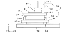
- Figures 3A to 3C are views of the main parts of the exposure apparatus as viewed in the Y direction
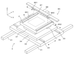
- Figure 4 is a perspective view that shows a schematic diagram of the configuration of the stage drive mechanism.
- Figures 3A to 3C correspond to side views of the exposure apparatus 1 as viewed in the (+Y) direction, but in order to clearly show the configuration of the stage drive mechanism 3 in particular, the light irradiation unit 40, alignment unit 5, control unit 9, etc. are omitted.
- the dashed arrows and dashed-dotted arrows shown near each component of the apparatus indicate the direction of movement of that component.
- a gantry-shaped support frame 101 is attached to a base portion 100 so as to straddle the stage driving mechanism 3 and the stage 2 supported by it in the X direction.
- the exposure heads 41 of the exposure unit 4 are attached to this support frame 101.
- only one exposure head 41 is shown as a representative example, but the number of exposure heads 41 is not limited to this and can be any number.
- they are disposed at equal intervals in the X direction. They move together relative to the substrate S during scanning movement.
- the relative movement between the exposure head 41 and the substrate S is achieved by the stage drive mechanism 3 moving the stage 2. That is, the stage drive mechanism 3 alternates between main scanning movement, which moves the stage 2 continuously in the Y direction, and sub-scanning movement, which moves the stage 2 a predetermined pitch in the X direction. In this way, the incident position on the substrate S of the exposure beam emitted from the exposure head 41 changes, and ultimately an exposure operation for the entire substrate S is achieved.
- the position detection mechanism 8 is responsible for detecting the position of the stage 2 during these operations. Specifically, as shown in FIG. 4, a linear scale 81 extending in the Y direction is attached to the upper surface of the stage 2 near the end on the (+X) side.
- the linear scale 81 is made of, for example, a glass plate, and is a two-dimensional linear scale with scales (gradations) engraved at predetermined intervals along both the X and Y directions, as described below.
- X-direction scale we mean a scale in which graduations are arranged at predetermined intervals along the X direction and which is used to detect a position in the X direction.
- Y-direction scale we mean a scale in which graduations are arranged at predetermined intervals along the Y direction and which is used to detect a position in the Y direction.
- a reading head 82 is provided above the linear scale 81.
- the reading head 82 optically reads the scale of the linear scale 81 and outputs a signal according to the reading result.
- the reading head 82 is a two-dimensional reading head that can individually read the X-direction scale and the Y-direction scale provided on the two-dimensional linear scale 81.
- the output signal from the reading head 82 is input to a position calculation unit 915 of the control unit 9.
- the position calculation unit 915 counts the signals output from the reading head 82 and calculates the position of the stage 2. In addition, it is possible to determine the moving speed and moving amount from the change in position.
- the reading head 82 is attached to the support frame 101 via a linear motion mechanism 83 whose movable direction is the X direction.
- the linear motion mechanism 83 moves the reading head 82 in the X direction within a predetermined movable range in response to a control command from the control unit 9.
- a linear motion mechanism for example, a linear motor, a ball screw mechanism, or a rack and pinion mechanism can be used.
- the reading head 82 is positioned in the X direction at a position corresponding to the linear scale 81.
- the Y direction position of the reading head 82 does not change. Therefore, when the stage 2 moves in the Y direction (main scanning movement), the linear scale 81 passes directly below the reading head 82, and the reading head 82 sequentially reads the scales provided on the linear scale 81.
- the linear motion mechanism 83 moves the reading head 82 in the X direction in conjunction with the movement. This makes it possible to maintain the reading head 82 facing the linear scale 81 both before and after the sub-scanning movement.
- Figure 3B shows the position of the stage 2 when the laser light L emitted from the exposure head 41 is incident on the end of the substrate S on the (+X) side.
- Figure 3C shows the position of the stage 2 when the laser light L emitted from the exposure head 41 is incident on the end of the substrate S on the (-X) side.
- the movement range of the stage 2 in the sub-scanning movement is set so that the exposure beam L is irradiated over the entire area of the substrate S, including both ends in the X direction. Therefore, the movable range of the reading head 82 is also set so that it is positioned opposite the linear scale 81 over the entire movement range of the stage 2.
- the movable range is determined to include both the position directly above the linear scale 81 when the stage 2 is at the position closest to the (-X) direction within its movement range, as shown in Figure 3B, and the position directly above the linear scale 81 when the stage 2 is at the position closest to the (+X) direction within its movement range, as shown in Figure 3C.
- the amount of movement of the stage 2 and the reading head 82 is substantially the same as the length of the substrate S in the X direction.
- each exposure head 41 only needs to expose a partial area of the substrate S, so the amount of movement required of the stage 2 and the reading head 82 is smaller.
- FIGS. 5A to 5C are diagrams showing an example configuration in which two sets of exposure heads are provided.
- FIG. 5A for example, when the arrangement pitch P of the two sets of exposure heads 41, 41 is set to half the X-direction length Wx of the substrate S, each exposure head 41 only needs to expose half of the entire surface of the substrate S in the X-direction. Therefore, as shown in FIGS. 5B and 5C, the amount of movement of the stage 2 and reading head 82 can be smaller than in the example shown in FIGS. 3B and 3C. The more exposure heads 41 are provided, the smaller the amount of movement of the stage 2 and reading head 82.
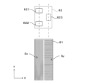
- FIGS. 6A and 6B are diagrams explaining the principle of position detection in the position detection mechanism.
- the position detection mechanism 8 in this embodiment detects the position of the stage 2 by combining a two-dimensional linear scale 81 with a reading head 82 that reads it.
- the reading head 82 has three optical sensors 821, 822, and 823 that optically detect the scales.
- the linear scale 81 has an X-direction scale Sx formed at a constant pitch in the X-direction, and a Y-direction scale Sy formed at a constant pitch in the Y-direction.
- a two-dimensional linear scale with such a simple scale pattern is used as an example.
- various other scale patterns are in practical use as two-dimensional linear scales, and it is possible to appropriately select and use one of these in this embodiment.
- the resolution of the scale used is higher than the accuracy required for the stage position control of this device.
- linear scales with resolution on the order of nanometers are commercially available, and can be suitably applied to this embodiment.
- optical sensor 823 is positioned to read the Y-direction scale Sy. Meanwhile, the other two optical sensors 821, 822 are positioned to read the X-direction scale Sx, and their positions are different in the Y direction.
- the optical sensors that can read the X-direction scale may be referred to simply as the "X-direction sensor”
- the optical sensor that can read the Y-direction scale for example, optical sensor 823 in this example
- a single optical sensor can read two types of scales that are perpendicular to each other, such as a two-dimensional image sensor, it is possible for that single optical sensor to function both as an "X-direction sensor” and a "Y-direction sensor.”
- the position detection mechanism 8 can detect the position of the stage 2 in each of the X and Y directions, and the amount of rotation (yawing) of the stage 2 around the ⁇ axis parallel to the Z axis. Specifically, the position of the stage 2 in the X direction can be detected based on the reading result of at least one of the optical sensors 821 and 822. In addition, the position of the stage 2 in the Y direction can be detected based on the reading result of the optical sensor 823. Furthermore, as will be explained below, the amount of yawing of the stage 2 can be obtained by comparing the reading results of the optical sensors 821 and 822. These calculations are performed by the position calculation unit 915 of the control unit 9.
- the X-direction positions of the stage 2 calculated based on the results of the two optical sensors 821, 822 reading the X-direction scale Sx differ from each other.
- the X-direction positions of the stage 2 calculated from the outputs of the optical sensors 821, 822 are represented by the symbols X1, X2, respectively.
- the distance in the Y direction between the two optical sensors 821, 822 is represented by the symbol d.
- the exposure operation in this embodiment is configured as follows.
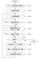
- FIG. 7 is a flow chart showing the processing contents of the exposure operation in this embodiment.
- This processing is realized by the CPU 91 of the control unit 9 executing a control program 931 stored in the storage 93. Note that this processing is started in a state where the substrate S to be imaged is placed on the stage 2 and a predetermined alignment adjustment has been performed in advance, but since the alignment adjustment technology is well known, a description thereof will be omitted here.
- the stage 2, with the substrate S placed in the correct position, is positioned to a predetermined initial position by the stage driving mechanism 3 (step S101). Then, position detection by the position detection mechanism 8 is started (step S102), and the stage driving mechanism 3 starts main scanning movement by moving the stage 2 in the Y direction (step S103). While the stage 2 is moving, the position detection mechanism 8 detects the stage position at all times, and the operation of the stage driving mechanism 3 and the exposure head 41 is controlled according to the result.
- step S104 When the stage 2 moves to the exposure start position, that is, the position where the incident position of the light beam L emitted from the exposure head 41 reaches one end of the substrate S (step S104), exposure of the substrate S by the exposure head 41 begins (step S105). At that time, correction of the stage position (X direction, ⁇ direction) and control of the exposure head 41 (spatial light modulator 400) (Y direction) are performed as needed based on the detection result of the stage position.
- step S106 When the stage 2 moves in the Y direction and reaches the exposure end position where exposure of one stripe is completed (step S106), it is then determined whether exposure of the entire substrate S is completed (step S107). If exposure of the entire surface of the substrate S is completed (YES in step S107), the process ends.
- step S108 the stage 2 is stepped in the sub-scanning direction at a predetermined pitch. This shifts the incident position of the exposure beam from the exposure head 41 in the X direction.
- the linear motion mechanism 83 then moves the reading head 82 in the X direction in accordance with the amount of movement of the stage 2 (step S109). The reason why the stage 2 and the reading head 82 are moved in two stages at different times in this manner is as follows.
- FIG. 8 shows the movement of the stage 2 and the reading head 82.
- one of the X-direction scales Sx is highlighted to clarify the positional relationship between the sub-figures and make it easier to understand, but such a distinction is not necessarily made in the actual device.
- step S108 as shown by arrow A in FIG. 8, only the stage 2 moves in the X-direction, for example, in the (+X) direction, with the reading head 82 (more precisely, the X-direction sensors 821, 822) fixed.
- the X-direction sensors 821, 822 are still operating, so that the amount of movement of the stage 2 in the X-direction can be detected.
- the amount of movement M1 detected at this time is the amount of movement of the stage 2 relative to the exposure head 41 fixed to the support frame 101, and this is information used to control the exposure operation.
- step S109 only the reading head 82 moves in the (+X) direction while the stage 2 remains stationary.
- the stage 2 is shown as having moved in the (-X) direction relative to the reading head 82.
- the reading head 82 continues to operate during this time, so that the amount of movement M2 of the reading head 82 relative to the stage 2 can be found.
- the position of each reading head is fixed in accordance with the movement pitch, so there is no need to consider positional deviations between the stage.
- the reading head 82 itself moves, making the relative movement with the stage 2 more complex. Specifically, for example, positional deviations may occur between the stage 2 and the reading head 82.
- the difference between the amount of movement M1 of the stage 2 detected when the reading head 82 is fixed and the amount of movement M2 of the reading head 82 detected when the stage 2 is fixed represents the relative amount of movement of the reading head 82 with respect to the stage 2, that is, the amount of "misalignment" ⁇ M described above.
- the stage position detected after the Nth (N is a natural number) sub-scanning movement includes the above-mentioned misalignment that occurs when the reading head 82 moves.
- the amount of movement M3 of the stage 2 obtained from the detection result of the reading head 82 in the (N+1)th sub-scanning movement includes the above-mentioned misalignment that occurs when the reading head 82 moves between the Nth stage movement and the (N+1)th stage movement.
- the original movement amount M4 of the stage 2 in the (N+1)th sub-scanning movement can be accurately determined by adding or subtracting the offset amount ⁇ M corresponding to the magnitude of the positional deviation to the movement amount M3 determined from the detection result of the reading head 82.
- the positional deviation with respect to the stage 2 accumulates each time the reading head 82 moves. For this reason, when determining the stage position based on the initial position, for example, it is possible to properly determine the stage position by accumulating the amount of positional deviation for each movement and correcting the stage movement amount from the initial position using this accumulated value.
- the hardware configuration requirement for enabling such processing is that the linear scale 81 must be read without moving the reading head 82 both before and after one sub-scanning movement of the stage 2. This requirement can be met by appropriately setting the readable range (field of view) of the reading head 82, the X-direction size of the linear scale 81, and the position of the reading head 82 relative to the linear scale 81.
- the position of the stage 2 during main scanning movement and sub-scanning movement is detected by a position detection mechanism 8 that uses the measurement principle of a linear encoder that combines a linear scale 81 and a reading head 82.
- the linear scale 81 extends in the Y direction, which is the main scanning direction, and can continuously detect the position of the stage 2 during main scanning movement.
- the reading head 82 is moved in accordance with the step movement of the stage 2 (linear scale 81), making it possible for the reading head 82 to read the scale at each position in the sub-scanning direction. This eliminates the need to provide multiple reading heads in the sub-scanning direction, making it possible to prevent the device from becoming larger and the costs from increasing as a result.
- the linear scale 81 is a two-dimensional scale, and the reading head 82 is equipped with multiple optical sensors 821-823 to enable reading of the scale in both the X and Y directions. From these reading results, the position detection mechanism 8 can detect the position of the stage 2 in the X and Y directions, and the orientation of the stage 2 in the ⁇ direction (yaw direction).
- the movement of the reading head 82 is performed exclusively at a different timing than the movement of the stage 2, that is, so that their movement periods do not overlap in time.
- the stage 2 is moved while the reading head 82 is stationary, and the amount of movement relative to the reading head 82 is detected by the reading head 82.
- the movement of the reading head 82 is performed while the stage 2 is stationary, and during this time the amount of movement of the reading head 82 relative to the stage 2 is detected by the reading head 82. Note that here, the stage 2 is first moved in the sub-scanning direction, and then the reading head 82 is moved, but this order can be reversed.
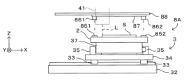
- Second Embodiment 9A to 9C and 10 are diagrams showing a schematic configuration of a main part of an exposure apparatus 1A as a second embodiment of a drawing apparatus according to the present invention. More specifically, Figs. 9A to 9C are diagrams showing the main part of the exposure apparatus 1A of the second embodiment as viewed in the Y direction, and Fig. 10 is a perspective view showing a schematic configuration of a stage driving mechanism 3 and its surroundings.
- the configuration of the position detection mechanism is different from that of the first embodiment, but the other configurations and basic operations are common to those of the first embodiment. Therefore, the same reference numerals are used for the configurations common to the first embodiment, and detailed explanations will be omitted.
- the position detection mechanism 8A of the exposure apparatus 1A in this embodiment includes two linear scales 851, 852 provided on the stage 2, two reading heads 861, 862, a movable member 87 that integrally supports these, and a linear motion mechanism 88 that moves the movable member 87 in the X direction.
- One linear scale 851 is provided near the end of the stage 2 on the (-X) side, and the other linear scale 852 is provided near the end of the stage 2 on the (+X) side, both extending in the Y direction.
- the two reading heads 861, 862 are attached to the lower part of a movable member 87 extending in the X direction, at different positions in the X direction, and at the same or approximately the same pitch as the arrangement pitch of the linear scales 851, 852 on the stage 2.
- the linear motion mechanism 88 moves the movable member 87 in the X direction in response to a control command from the control unit 9. As a result, the two reading heads 861, 862 move integrally in the X direction.
- the reading head 82 in the first embodiment two reading heads may be provided, each supported by an independent linear motion mechanism.
- the number of exposure heads 41 is arbitrary, and by arranging multiple exposure heads 41, the range of movement in the sub-scanning movement of the stage 2 can be reduced. Even in this case, the position detection mechanism 8A only needs to be provided with two sets of linear scales and reading heads corresponding to both ends of the stage 2, regardless of the number of exposure heads 41.
- the reduced range of movement of the stage 2 means that the range of movement of each reading head can also be reduced.
- the reading head 861 reads the scale of the linear scale 851. Meanwhile, the reading head 862 reads the scale of the linear scale 852. That is, in this embodiment, a linear encoder is provided at each end of the stage 2 in the X direction.
- position detection is performed by linear encoders at both ends of the stage 2 in the X direction.
- the principle of position detection and the exposure operation including the processing are basically the same as those in the first embodiment. In other words, in this embodiment as well, it is possible to realize the exposure operation by executing the processing shown in FIG. 7.
- stage 2 has a tilt in the ⁇ direction.
- the distance between the two optical sensors that are compared to detect the tilt of the stage 2 in the ⁇ direction can be made sufficiently large. Therefore, in terms of tilt detection accuracy, the second embodiment may actually be better than the first embodiment.
- each of the reading heads 861, 862 can read the Y-direction scale, it is possible to detect the Y-direction position of the stage 2 and the amount of tilt around the ⁇ -axis. In this sense, at least one of the reading heads 861, 862 does not need to have the function of reading the X-direction scale.
- the corresponding linear scales 851, 852 do not necessarily need to be two-dimensional linear scales either; it is sufficient if a Y-direction scale is provided.
- one of linear scales 851, 852 can be a one-dimensional scale and the other a two-dimensional scale.
- those configured to read only the Y-direction position can be used.
- the reading head 82 in the first embodiment is provided with two optical sensors 821, 822 for reading the X-direction scale so that it can detect not only the position in the X-direction but also the attitude of the stage 2 around the ⁇ -axis.
- the attitude of the stage 2 can be determined by comparing the detection results of the Y-direction positions at both ends of the stage 2, only one optical sensor may be used to read the X-direction scale.
- the position detection mechanism 8A has the following configuration: (1) A configuration in which the linear scales 851 and 852 are both two-dimensional scales, (2) A configuration in which one of the linear scales 851 and 852 is a two-dimensional scale and the other is a one-dimensional (Y direction) scale; Both of the above may be true.
- the linear scales facing each other are two-dimensional scales.
- A A configuration having two X-direction sensors and one Y-direction sensor, as shown in FIG. 6A;
- B A configuration having one X-direction sensor and one Y-direction sensor;
- the opposing linear scale is a one-dimensional scale, it is sufficient to provide at least one Y-direction sensor.
- the two linear scales 851, 852 can each be a one-dimensional (Y direction) scale, and the reading heads 861, 862 can also have only a Y direction sensor. Even with this configuration, it is possible to detect at least the Y direction position and the ⁇ direction tilt of the stage 2 with the same accuracy as the above embodiment.
- the exposure apparatus 1, 1A corresponds to one aspect of the "imaging apparatus” of the present invention.
- the substrate S corresponds to the “substrate” of the present invention
- the stage 2 corresponds to the "stage” of the present invention.
- the exposure unit 4, and in particular the exposure head 41, functions as the “imaging section” of the present invention.
- the stage driving mechanism 3 functions as the "first moving mechanism” of the present invention.
- linear scales 81, 851, and 852 correspond to the "linear scale” of the present invention
- reading heads 82, 861, and 862 correspond to the “reading head” of the present invention
- linear motion mechanisms 83 and 88 correspond to the "second moving mechanism” of the present invention.
- the position detection mechanisms 8 and 8A having these and the position calculation unit 915 function as a whole as the "position detection unit” of the present invention.
- a linear scale is attached to one end or both ends in the X-direction of the flat upper surface of the stage 2.
- the linear scale does not need to be attached directly to the stage as long as it is configured to move integrally with the stage and, more preferably, so that the relative positional relationship between them does not change.
- the stage and linear scale may each be attached to a common base member.
- the reading heads 82, 861, 862 in the position detection mechanisms 8, 8A in the above embodiments are attached to a gantry-shaped support frame 101 that straddles the stage 2. For this reason, the distance between the linear scales 81, 851, 852 is relatively large.
- the placement of the reading heads is not limited to this, and it is sufficient that they are supported in a position where they can read the linear scale, are independent of the movement of the stage 2, and do not interfere with said movement.
- the information about the position and orientation of the stage 2 detected by the position detection mechanisms 8 and 8A can be used in any way.
- the information is used to control the exposure head 41 and the stage drive mechanism 3, but it can also be used for other purposes, such as detecting anomalies based on the position detection results.
- linear scales are arranged at both ends of the stage 2 in the X direction.
- the two linear scales only need to be arranged at different positions in the X direction, and may be provided, for example, at two locations on one side of the stage.
- the position of stage 2 in the X and Y directions is detected by reading a linear scale provided at the end of stage 2 in the X direction.
- the linear scale it is sufficient for the linear scale to be at least capable of "detecting the position of the stage in the main scanning direction using the principles of a linear encoder.” Therefore, other means may be used for detecting the position in the X direction.
- a linear scale extending in the X direction may be provided on the stage, and the position in the X direction may be detected by reading this.
- the exposure apparatus 1, 1A in the above embodiment is a specific example of the "drawing apparatus" according to the present invention, which is an apparatus that draws a pattern by exposing the surface of a substrate on which a photosensitive layer is formed with a light beam modulated based on drawing data.
- the manner of drawing is not limited to this and is arbitrary, and may be, for example, a manner in which drawing is performed by exposure via a photomask, reticle, etc., or a manner in which drawing is performed by directly processing the substrate surface with laser light.
- the exposure apparatus 1, 1A in the above embodiment is equipped with a step-and-scan type stage drive mechanism that alternates between continuous stage movement in the main scanning direction and step movement in the sub-scanning direction.
- the present invention can also be applied to a drawing device that uses a step-and-repeat type movement mode, for example, in which drawing is performed sequentially for each predetermined two-dimensional area while changing the position.
- the linear scale may be a two-dimensional linear scale having scales in both the main scanning direction and the sub-scanning direction.
- the position detection unit can detect the magnitude of yawing of the stage in addition to the stage position in each of the main scanning direction and the sub-scanning direction based on the reading result of the reading head.
- the position detection unit may have a plurality of linear scales arranged at different positions in the sub-scanning direction, and a plurality of reading heads arranged corresponding to each of the plurality of linear scales.
- a position detection unit configured in this way can detect the magnitude of the yawing of the stage in addition to the position of the stage in the main scanning direction.
- At least one of the multiple linear scales may be a two-dimensional linear scale having scales in both the main scanning direction and the sub-scanning direction.
- the drawing device and drawing method according to the present invention may be configured so that the period during which the stage moves in the sub-scanning direction and the period during which the read head moves do not overlap, that is, these movements are performed exclusively at different times.
- the stage moves while the read head is stationary, and only the amount of stage movement can be obtained from the linear scale reading results at this time.
- the amount of movement of the read head relative to the stage can be obtained from the linear scale reading results when the read head moves while the stage is stationary.
- This invention is suitable for technical fields in which drawing is performed on substrates to form patterns on substrates such as semiconductor substrates, semiconductor package substrates, printed wiring boards, or glass substrates.
Landscapes
- Physics & Mathematics (AREA)
- General Physics & Mathematics (AREA)
- Exposure And Positioning Against Photoresist Photosensitive Materials (AREA)
- Length Measuring Devices By Optical Means (AREA)
Priority Applications (1)
| Application Number | Priority Date | Filing Date | Title |
|---|---|---|---|
| KR1020257024983A KR20250129065A (ko) | 2023-02-27 | 2023-12-14 | 묘화 장치 및 묘화 방법 |
Applications Claiming Priority (2)
| Application Number | Priority Date | Filing Date | Title |
|---|---|---|---|
| JP2023027990A JP2024121091A (ja) | 2023-02-27 | 2023-02-27 | 描画装置および描画方法 |
| JP2023-027990 | 2023-02-27 |
Publications (1)
| Publication Number | Publication Date |
|---|---|
| WO2024180866A1 true WO2024180866A1 (ja) | 2024-09-06 |
Family
ID=92589482
Family Applications (1)
| Application Number | Title | Priority Date | Filing Date |
|---|---|---|---|
| PCT/JP2023/044760 Ceased WO2024180866A1 (ja) | 2023-02-27 | 2023-12-14 | 描画装置および描画方法 |
Country Status (4)
| Country | Link |
|---|---|
| JP (1) | JP2024121091A (https=) |
| KR (1) | KR20250129065A (https=) |
| TW (1) | TWI897171B (https=) |
| WO (1) | WO2024180866A1 (https=) |
Citations (4)
| Publication number | Priority date | Publication date | Assignee | Title |
|---|---|---|---|---|
| WO2017057577A1 (ja) * | 2015-09-30 | 2017-04-06 | 株式会社ニコン | 露光装置、フラットパネルディスプレイの製造方法、デバイス製造方法、及び露光方法 |
| WO2017057587A1 (ja) * | 2015-09-30 | 2017-04-06 | 株式会社ニコン | 露光装置、フラットパネルディスプレイの製造方法、及びデバイス製造方法 |
| WO2018062497A1 (ja) * | 2016-09-30 | 2018-04-05 | 株式会社ニコン | 移動体装置、移動方法、露光装置、露光方法、フラットパネルディスプレイの製造方法、並びにデバイス製造方法 |
| WO2018062500A1 (ja) * | 2016-09-30 | 2018-04-05 | 株式会社ニコン | 移動体装置、移動方法、露光装置、露光方法、フラットパネルディスプレイの製造方法、並びにデバイス製造方法 |
Family Cites Families (2)
| Publication number | Priority date | Publication date | Assignee | Title |
|---|---|---|---|---|
| TWI622084B (zh) | 2006-09-01 | 2018-04-21 | 尼康股份有限公司 | Mobile body driving method, moving body driving system, pattern forming method and device, exposure method and device, component manufacturing method, and correction method |
| JP2012169549A (ja) | 2011-02-16 | 2012-09-06 | Dainippon Screen Mfg Co Ltd | 露光装置及び露光方法 |
-
2023
- 2023-02-27 JP JP2023027990A patent/JP2024121091A/ja active Pending
- 2023-12-14 KR KR1020257024983A patent/KR20250129065A/ko active Pending
- 2023-12-14 WO PCT/JP2023/044760 patent/WO2024180866A1/ja not_active Ceased
- 2023-12-29 TW TW112151479A patent/TWI897171B/zh active
Patent Citations (4)
| Publication number | Priority date | Publication date | Assignee | Title |
|---|---|---|---|---|
| WO2017057577A1 (ja) * | 2015-09-30 | 2017-04-06 | 株式会社ニコン | 露光装置、フラットパネルディスプレイの製造方法、デバイス製造方法、及び露光方法 |
| WO2017057587A1 (ja) * | 2015-09-30 | 2017-04-06 | 株式会社ニコン | 露光装置、フラットパネルディスプレイの製造方法、及びデバイス製造方法 |
| WO2018062497A1 (ja) * | 2016-09-30 | 2018-04-05 | 株式会社ニコン | 移動体装置、移動方法、露光装置、露光方法、フラットパネルディスプレイの製造方法、並びにデバイス製造方法 |
| WO2018062500A1 (ja) * | 2016-09-30 | 2018-04-05 | 株式会社ニコン | 移動体装置、移動方法、露光装置、露光方法、フラットパネルディスプレイの製造方法、並びにデバイス製造方法 |
Also Published As
| Publication number | Publication date |
|---|---|
| TW202435277A (zh) | 2024-09-01 |
| TWI897171B (zh) | 2025-09-11 |
| KR20250129065A (ko) | 2025-08-28 |
| JP2024121091A (ja) | 2024-09-06 |
Similar Documents
| Publication | Publication Date | Title |
|---|---|---|
| EP1921506A2 (en) | Position Detecting Method and Device, Patterning Device, and Subject to be detected | |
| JP2010231062A (ja) | 描画装置および描画方法 | |
| KR20090114037A (ko) | 노광 장치의 정렬 방법, 이를 이용한 감광막의 노광 방법및 감광막의 노광 방법을 수행하기 위한 노광 장치 | |
| WO2006090914A1 (en) | Calibration method for image rendering device and image rendering device | |
| JP7633044B2 (ja) | 露光方法および露光装置 | |
| JP4522142B2 (ja) | 露光装置、露光方法、及び基板製造方法 | |
| CN116736643A (zh) | 曝光装置以及曝光方法 | |
| WO2015052618A1 (ja) | 描画装置及び描画方法 | |
| WO2024180866A1 (ja) | 描画装置および描画方法 | |
| KR102886128B1 (ko) | 노광 방법 및 노광 장치 | |
| JP2012133122A (ja) | 近接露光装置及びそのギャップ測定方法 | |
| JP7633045B2 (ja) | 露光方法および露光装置 | |
| JP2006100590A (ja) | 近接露光装置 | |
| CN114967378A (zh) | 描画装置、描画方法、以及存储有程序的存储介质 | |
| JP2009237255A (ja) | 露光装置、及び露光方法 | |
| TWI901966B (zh) | 曝光裝置及曝光裝置中之光束間隔計測方法 | |
| JP2006093604A (ja) | 近接露光装置 | |
| JP4487688B2 (ja) | ステップ式近接露光装置 | |
| JP2025037489A (ja) | 露光装置 | |
| JP4487700B2 (ja) | 近接露光装置 | |
| JP2012198372A (ja) | 描画装置および描画方法 | |
| WO2025062747A1 (ja) | 描画装置、描画方法、プログラムおよび基板処理装置 | |
| KR20250017679A (ko) | 검출 장치, 노광 장치 및 검출 방법 | |
| JP5752970B2 (ja) | パターン描画装置、パターン描画方法 | |
| JP2006098774A (ja) | 近接露光装置 |
Legal Events
| Date | Code | Title | Description |
|---|---|---|---|
| 121 | Ep: the epo has been informed by wipo that ep was designated in this application |
Ref document number: 23925417 Country of ref document: EP Kind code of ref document: A1 |
|
| ENP | Entry into the national phase |
Ref document number: 1020257024983 Country of ref document: KR Free format text: ST27 STATUS EVENT CODE: A-0-1-A10-A15-NAP-PA0105 (AS PROVIDED BY THE NATIONAL OFFICE) |
|
| WWE | Wipo information: entry into national phase |
Ref document number: 1020257024983 Country of ref document: KR |
|
| WWP | Wipo information: published in national office |
Ref document number: 1020257024983 Country of ref document: KR |
|
| NENP | Non-entry into the national phase |
Ref country code: DE |
|
| 122 | Ep: pct application non-entry in european phase |
Ref document number: 23925417 Country of ref document: EP Kind code of ref document: A1 |