WO2024180643A1 - タービンホイール、および、過給機 - Google Patents
タービンホイール、および、過給機 Download PDFInfo
- Publication number
- WO2024180643A1 WO2024180643A1 PCT/JP2023/007199 JP2023007199W WO2024180643A1 WO 2024180643 A1 WO2024180643 A1 WO 2024180643A1 JP 2023007199 W JP2023007199 W JP 2023007199W WO 2024180643 A1 WO2024180643 A1 WO 2024180643A1
- Authority
- WO
- WIPO (PCT)
- Prior art keywords
- blade
- blades
- turbine wheel
- leading edge
- different
- Prior art date
- Legal status (The legal status is an assumption and is not a legal conclusion. Google has not performed a legal analysis and makes no representation as to the accuracy of the status listed.)
- Ceased
Links
Images




Classifications
-
- F—MECHANICAL ENGINEERING; LIGHTING; HEATING; WEAPONS; BLASTING
- F01—MACHINES OR ENGINES IN GENERAL; ENGINE PLANTS IN GENERAL; STEAM ENGINES
- F01D—NON-POSITIVE DISPLACEMENT MACHINES OR ENGINES, e.g. STEAM TURBINES
- F01D5/00—Blades; Blade-carrying members; Heating, heat-insulating, cooling or antivibration means on the blades or the members
- F01D5/02—Blade-carrying members, e.g. rotors
- F01D5/04—Blade-carrying members, e.g. rotors for radial-flow machines or engines
- F01D5/043—Blade-carrying members, e.g. rotors for radial-flow machines or engines of the axial inlet- radial outlet, or vice versa, type
- F01D5/048—Form or construction
-
- F—MECHANICAL ENGINEERING; LIGHTING; HEATING; WEAPONS; BLASTING
- F01—MACHINES OR ENGINES IN GENERAL; ENGINE PLANTS IN GENERAL; STEAM ENGINES
- F01D—NON-POSITIVE DISPLACEMENT MACHINES OR ENGINES, e.g. STEAM TURBINES
- F01D5/00—Blades; Blade-carrying members; Heating, heat-insulating, cooling or antivibration means on the blades or the members
- F01D5/12—Blades
- F01D5/14—Form or construction
- F01D5/16—Form or construction for counteracting blade vibration
-
- F—MECHANICAL ENGINEERING; LIGHTING; HEATING; WEAPONS; BLASTING
- F01—MACHINES OR ENGINES IN GENERAL; ENGINE PLANTS IN GENERAL; STEAM ENGINES
- F01D—NON-POSITIVE DISPLACEMENT MACHINES OR ENGINES, e.g. STEAM TURBINES
- F01D9/00—Stators
- F01D9/02—Nozzles; Nozzle boxes; Stator blades; Guide conduits, e.g. individual nozzles
- F01D9/026—Scrolls for radial machines or engines
-
- F—MECHANICAL ENGINEERING; LIGHTING; HEATING; WEAPONS; BLASTING
- F05—INDEXING SCHEMES RELATING TO ENGINES OR PUMPS IN VARIOUS SUBCLASSES OF CLASSES F01-F04
- F05D—INDEXING SCHEME FOR ASPECTS RELATING TO NON-POSITIVE-DISPLACEMENT MACHINES OR ENGINES, GAS-TURBINES OR JET-PROPULSION PLANTS
- F05D2220/00—Application
- F05D2220/40—Application in turbochargers
-
- F—MECHANICAL ENGINEERING; LIGHTING; HEATING; WEAPONS; BLASTING
- F05—INDEXING SCHEMES RELATING TO ENGINES OR PUMPS IN VARIOUS SUBCLASSES OF CLASSES F01-F04
- F05D—INDEXING SCHEME FOR ASPECTS RELATING TO NON-POSITIVE-DISPLACEMENT MACHINES OR ENGINES, GAS-TURBINES OR JET-PROPULSION PLANTS
- F05D2260/00—Function
- F05D2260/96—Preventing, counteracting or reducing vibration or noise
- F05D2260/961—Preventing, counteracting or reducing vibration or noise by mistuning rotor blades or stator vanes with irregular interblade spacing, airfoil shape
Definitions
- This disclosure relates to a turbine wheel and a supercharger.
- Turbochargers are known that are installed in the internal combustion engines of large ships or automobiles. Turbochargers use the flow of exhaust gas generated in the internal combustion engine to rotate a turbine impeller, which in turn rotates a compressor impeller that is installed coaxially with the turbine impeller. High-pressure air is sent from the compressor impeller to the combustion chamber, increasing the output of the internal combustion engine.
- the turbine impeller of the turbocharger disclosed in Patent Document 1 is configured to rotate using the flow of exhaust gas flowing through a scroll passage formed in the turbine housing.
- the exhaust gas that passes through the turbine impeller is discharged to the outside via a gas outlet portion formed in the turbine housing.
- Abnormal noises may occur as the turbine impeller rotates. For example, such noises occur when the blades of the turbine impeller interfere with a vortex generated at a tongue formed on the inner wall surface of the turbine housing, or when the blade tip of a following turbine impeller interferes with a vortex generated at the blade tip of a preceding turbine impeller. According to the inventor's knowledge, such abnormal noises tend to occur more noticeably when a specific relationship is established between the number of blades and the rotational frequency of the turbine impeller (or the frequency obtained by multiplying the rotational frequency by an integer of 2 or more).
- the objective of this disclosure is to provide a turbine wheel and a supercharger that can suppress the generation of abnormal noise.
- a turbine wheel includes: A turbine wheel provided in a turbine housing of a turbocharger, A hub connected to a rotating shaft of the turbocharger; a plurality of blades provided on the hub at intervals in a circumferential direction based on the rotation axis;
- the plurality of wings includes at least one first wing and at least one second wing having a different shape than the first wing.
- the turbocharger includes: A turbine wheel according to any one of claims 1 to 8; a turbine housing that houses the turbine wheel, The turbine housing includes: a scroll portion having a scroll passage formed therein, the scroll passage being located radially outside the turbine wheel and through which exhaust gas flows in the circumferential direction; and a tongue portion formed on an inner circumferential side of the scroll passage.
- This disclosure provides a turbine wheel and a supercharger that can suppress the generation of abnormal noise.
- FIG. 1 is a schematic cross-sectional view showing a turbocharger according to an embodiment.
- 1 is a schematic cross-sectional view of a turbine housing according to an embodiment
- FIG. 2 is a schematic meridional section of a turbine wheel according to an embodiment
- FIG. 1 is a schematic diagram illustrating a wing according to an embodiment.
- 4 is a schematic graph illustrating a shape of a leading edge of a first wing according to an embodiment.
- FIG. 6 is a schematic diagram of a turbine wheel according to another embodiment.
- expressions indicating that things are in an equal state such as “identical,””equal,” and “homogeneous,” not only indicate a state of strict equality, but also indicate a state in which there is a tolerance or a difference to the extent that the same function is obtained.
- expressions describing shapes such as a rectangular shape or a cylindrical shape do not only represent rectangular shapes or cylindrical shapes in the strict geometric sense, but also represent shapes that include uneven portions, chamfered portions, etc., to the extent that the same effect can be obtained.
- the expressions “comprise”, “include”, or “have” a certain element are not exclusive expressions excluding the presence of other elements.
- the same components are denoted by the same reference numerals and the description thereof may be omitted.
- ⁇ Overall configuration of turbocharger 1> 1 is a schematic cross-sectional view showing a turbocharger 1 according to an embodiment of the present disclosure.
- the turbocharger 1 of this example is mounted on a vehicle such as an automobile.
- the radial direction and the circumferential direction based on a rotating shaft 2 of the turbocharger 1 may be simply referred to as the radial direction and the circumferential direction, respectively.
- the axial direction of the rotating shaft 2 may be simply referred to as the axial direction.
- the turbocharger 1 includes a rotating shaft 2, a compressor wheel 4 connected to one end of the rotating shaft 2, a turbine wheel 3 connected to the other end of the rotating shaft 2, a compressor housing 6 that houses the compressor wheel 4, and a turbine housing 5 that houses the turbine wheel 3.
- the compressor housing 6 includes an intake section 10 in which an intake passage 10A is formed, and a scroll section 8 in which a scroll passage 8A is formed.
- FIG. 2 is a schematic cross-sectional view of a turbine housing 5 according to one embodiment of the present disclosure.
- the turbine housing 5 includes a scroll section 7 having a scroll passage 7A formed therein, and a tongue portion 51 formed on the inner circumferential side of the scroll passage 7A.
- the tongue portion 51 separates the scroll passage 7A from the passage 9 formed in the exhaust gas flow direction from the scroll passage 7A.
- the tongue portion 51 extends at an angle to the axial direction (see FIG. 3).
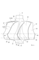
- ⁇ Turbine wheel 3> 3 is a schematic diagram of a turbine wheel 3 according to an embodiment of the present disclosure.
- the turbine wheel 3 illustrated in the figure is a radial turbine, but the present disclosure is not limited to this, and a mixed flow turbine or the like may be adopted.
- An arrow R in the figure indicates the rotation direction of the turbine wheel 3.
- the turbine wheel 3 comprises a hub 31 having a hub surface 32 inclined with respect to the axis S of the rotating shaft 2 (see FIG. 1), and a plurality of blades 33 provided on the hub surface 32.
- the hub 31 is connected to the rotating shaft 2.
- the plurality of blades 33 are spaced apart in the rotational direction of the hub 31, and each blade 33 includes a leading edge 35, a trailing edge 36, and a tip end 37.
- the hub surface 32 of the turbine wheel 3 may be provided with only long blades as shown in FIG. 3, or may be provided with long blades and short blades (not shown). However, in an embodiment in which long blades and short blades are mixed, all of the plurality of blades 33 correspond to long blades.
- FIG. 4 is a schematic meridian section showing a blade 33 according to one embodiment of the present disclosure.
- the tip end 39 is a portion of the leading edge 35 that connects to the tip end 37.
- the hub end 38 is a portion of the leading edge 35 that intersects with an imaginary line L9 that extends from the hub surface 32 toward the leading edge 35.
- the imaginary line L9 is an imaginary curve that includes the generatrix of the hub 31 (i.e., the curve indicated by reference numeral 32 in FIG. 4) when viewed along the direction of rotation of the turbine wheel 3.
- trailing edge tip end 41 the portion of the trailing edge 36 that connects to the tip end 37
- trailing edge hub end 42 the end of the trailing edge 36 opposite the trailing edge tip end 41
- the leading edge 35 of this embodiment has a twisted shape such that the rotational phase changes as the position in the axial direction changes. More specifically, the leading edge 35 is formed so that the rotational phase at the hub side end 38 is different from the rotational phase at the tip side end 39.
- the difference between the two rotational phases may be referred to as the leading edge inclination angle.
- the leading edge inclination angle correlates with the time it takes for the blade 33 to pass the tongue 51. This time is the time it takes from when the hub end 38 of the leading edge 35 passes the tongue 51 to when the tip end 39 passes the tongue 51.
- Vortices are generated inside the turbine housing 5.
- a vortex generated near the tongue 51 a vortex generated near the leading edge 35 of the blade 33, or a vortex generated near the trailing edge 36 of the blade 33 (the vortex generated near the tongue 51 is indicated by arrow A in FIG. 2).
- the vortex generated near the tongue 51 is indicated by arrow A in FIG. 2.
- the blade 33 periodically hits the vortex, the vortex gradually grows and eventually generates abnormal noise.
- the inventor of the present application came up with the idea that if the way the blade 33 hits the vortex during one rotation of the turbine wheel 3 is made irregular, the growth of the vortex can be suppressed, and as a result, the generation of abnormal noise can be suppressed.
- configurations that embody this idea will be described in order as a first embodiment and a second embodiment.
- the blades 33 include at least one first blade 11 and at least one second blade 12, and the first blade 11 and the second blade 12 have different shapes.
- various configurations can be adopted.
- the shape of the leading edge 35 may be made different between the first blade 11 and the second blade 12
- the shape of the trailing edge 36 may be made different between the first blade 11 and the second blade 12, or a combination of these configurations may be adopted.
- the shape of the portion on the tip end 37 side of the leading edge 35 may be different, or the shape of the portion on the hub side end 38 of the leading edge 35 may be different.
- the leading edge inclination angle described later may be different.
- the shape of the trailing edge 36 is different, the shape of the trailing edge tip end 41 of the trailing edge 36 may be different, the shape of the trailing edge hub end 42 of the trailing edge 36 may be different, or a combination of these may be used.
- the first blade 11 and the second blade 12, which are different in shape from each other, are included in the plurality of blades 33. Therefore, even if a vortex occurs inside the turbine housing 5, the way in which the plurality of blades 33 and the vortex come into contact during one rotation of the turbine wheel 3 can be made irregular, and the growth of the vortex can be suppressed. As a result, the turbine wheel 3 can suppress the generation of abnormal noise. Also, if the shape of the leading edge 35 differs between the first blade 11 and the second blade 12, the time required for the leading edge 35 to pass through the vortex generated near the tongue portion 51 of the turbine housing 5 becomes irregular.
- the leading edge 35 is prevented from periodically interfering with the vortex, and the generation of abnormal noise can be suppressed.
- the shape of the trailing edge 36 differs between the first blade 11 and the second blade 12, the time required for the trailing edge 36 to pass through the above-mentioned vortex generated near the trailing edge 36 of the blade 33 becomes irregular. As a result, the trailing edge 36 of the blade 33 is prevented from periodically interfering with the vortex, and the generation of abnormal noise can be suppressed.
- FIG. 5 is a schematic graph showing the shape of the leading edge 35 of each of the first blade 11 and the second blade 12, and in the graph area where the dashed line and the solid line overlap, the solid line is preferentially illustrated.
- the horizontal axis of the graph is the axial distance starting from the trailing edge tip side end 41, which corresponds to the dimension Za in FIG. 4.
- the vertical axis shows the rotational phase ( ⁇ ), which is the position in the circumferential direction, and the positive direction of ⁇ is the rotational direction of the turbine wheel 3 (arrow R in FIG. 3).
- the thick solid line shown on the graph shows the relationship between the rotational phase of the first blade 11 defined by the tip end 37 in FIG. 4 and the axial distance
- the normal solid line shows the relationship between the rotational phase of the first blade 11 defined by L9 and the axial distance
- the thick dashed line indicates the relationship between the rotation phase of the second blade 12 defined by the tip end 37 and the axial distance
- the normal dashed line indicates the relationship between the rotation phase of the second blade 12 defined by L9 and the axial distance.
- the dimensions ⁇ 1 and ⁇ 2 shown in FIG. 5 indicate the leading edge inclination angles of the first blade 11 and the second blade 12, respectively. As shown in both figures, the leading edge inclination angles are different between the first blade 11 and the second blade 12. The leading edge 35 of the blade 33 is likely to hit the vortex generated near the tongue portion 51 of the turbine housing 5.
- the first blade 11 and the second blade 12 have different leading edge inclination angles, it is possible to make the time required for the leading edge 35 of each blade 33 to pass through the vortex irregular. This prevents the leading edge 35 of the blade 33 from periodically interfering with the vortex, thereby suppressing the generation of abnormal noise.
- the shapes of any two adjacent blades 33 among the plurality of blades 33 may be different from each other.
- a configuration may be adopted in which the plurality of blades 33 are composed only of a plurality of first blades 11 and a plurality of second blades 12, and the first blades 11 and the second blades 12 are arranged alternately in the circumferential direction.
- each of the blades 33 may have a different shape.
- the leading edge inclination angle may be different for all of the blades 33.
- the present disclosure is not limited to this.
- a configuration in which the shape of the trailing edge 36 differs between the first blade 11 and the second blade 12 may be adopted.
- vortices may be generated near the trailing edges 36 of the blades 33.
- the vortex grows and abnormal noise is generated.
- the blades 33 can hit the vortex irregularly, and abnormal noise can be suppressed.
- FIG. 6 is another schematic diagram showing a specific configuration of the turbine wheel 3.
- a plurality of blades 33 constituting the turbine wheel 3 are illustrated in a schematic manner.
- the plurality of blades 33 includes a plurality of first blades 11, and a blade space Bs is formed between two first blades 11 arranged continuously in the circumferential direction.
- the number of first blades 11 is three
- the number of blade spaces Bs is three.
- at least one third blade 13 is disposed in each blade space Bs.
- the third blade 13 may have a shape different from that of the first blade 11, and may have the same shape as the second blade 12 described above, or may have a shape different from that of the second blade 12.
- the number of third blades 13 arranged in the blade spaces Bs differs among the three blade spaces Bs.
- the number of third blades 13 arranged in the first blade space Bs is two
- the number of third blades 13 arranged in the second blade space Bs is three
- the number of third blades 13 arranged in the third blade space Bs is four.
- the multiple blades 33 illustrated in FIG. 6 are arranged so that there are two or more blade pitches.
- two third blades 13 are arranged on either side of each first blade 11, and the blade pitch ( ⁇ 1) between the third blade 13 and the first blade 11 on one side is different from the blade pitch ( ⁇ 2) between the third blade 13 and the first blade 11 on the other side. This relationship holds for each first blade 11.
- the blade pitch is, as an example, the pitch of the tip side end 39 (see FIG. 3).
- the period during which the blades 33 come into contact with the vortex during one rotation of the turbine wheel 3 can be made uneven, thereby suppressing the growth of the vortex. This makes it possible to suppress the generation of abnormal noise.
- the blade pitch may all be different among the multiple blades 33, and the above advantages can still be obtained in this case.
- the blade pitch of any two adjacent blades 33 among the plurality of blades 33 is 2° or more greater than the angle obtained by dividing 360° by the number of the plurality of blades 33.
- both ⁇ 1 and ⁇ 2 are 2° or more greater than the above angles.
- the pitch of the tip end 39 of any two adjacent blades 33 among the plurality of blades 33 is within 3°.
- a turbine wheel (3) according to at least one embodiment of the present disclosure, A turbine wheel provided in a turbine housing (5) of a turbocharger (1), A hub (31) connected to the rotating shaft (2) of the turbocharger; a plurality of blades (33) provided on the hub at intervals in a circumferential direction relative to the rotation axis;
- the plurality of wings includes at least one first wing (11) and at least one second wing (12) having a shape different from that of the first wing.
- the multiple blades include first and second blades with different shapes, so even if a vortex occurs inside the turbine housing, the way the multiple blades come into contact with the vortex during one rotation of the turbine wheel can be made irregular, and the growth of the vortex can be suppressed. This makes it possible for the turbine wheel to suppress the generation of abnormal noise.
- Each of the plurality of wings includes a leading edge (35); The shape of the leading edge of the first wing and the shape of the leading edge of the second wing are different from each other.
- leading edges of the blades are likely to come into contact with the vortexes that are generated at the tongue portion formed in the turbine housing.
- the shapes of the leading edges of the first blade and the second blade are different from each other, so it is possible to make the time required for the leading edge of each blade to pass through the vortex irregular. This prevents the leading edges of the blades from periodically interfering with the vortex, and suppresses the generation of abnormal noise.
- the turbine wheel according to 1) or 2) above, When the circumferential position is defined as the rotational phase and the difference between the rotational phase at the hub side end (38) of the leading edge and the rotational phase at the tip side end (39) of the leading edge is defined as the leading edge inclination angle, the leading edge inclination angle at the first blade and the leading edge inclination angle at the second blade are different from each other.
- leading edges of the blades are likely to come into contact with the vortexes that are generated at the tongue portion formed in the turbine housing.
- the first blade and the second blade have leading edge inclination angles relative to each other, so that the time required for the leading edge of each blade to pass through the vortex can be made irregular. This prevents the leading edges of the blades from periodically interfering with the vortex, and suppresses the generation of abnormal noise.
- each of the plurality of wings includes a trailing edge (36); The shape of the trailing edge of the first wing and the shape of the trailing edge of the second wing are different from each other.
- the configuration of 4) above makes it possible to make the time required for the trailing edge of the blade to pass through a vortex that occurs near the trailing edge irregular. This prevents the trailing edge of the blade from periodically interfering with the vortex, thereby suppressing the generation of abnormal noise.
- the configuration of 5) above changes the way the blades and vortexes come into contact with each other between two adjacent blades, which helps to suppress the generation of abnormal noise.
- each of the plurality of wings has a different shape.
- the configuration of 6) above further changes the way the blades and vortexes come into contact during one rotation of the turbine wheel, thereby suppressing the generation of abnormal noise.
- the configuration of 7) above makes it possible to make the period in which the blades come into contact with the vortex more uneven during one rotation of the turbine wheel, thereby suppressing the growth of the vortex. This makes it possible to suppress the generation of abnormal noise.
- the turbine wheel according to any one of 1) to 7) above,
- the plurality of blades are arranged so as to have two or more types of blade pitch.
- the configuration of 8) above makes it possible to make the period during which the blades come into contact with the vortex uneven during one rotation of the turbine wheel, thereby suppressing the growth of the vortex. This makes it possible to suppress the generation of abnormal noise.
- the turbine wheel according to 8) above The blade pitch of any two adjacent blades among the plurality of blades is 2° or more larger than an angle obtained by dividing 360° by the number of the plurality of blades.
- the configuration of 9) above makes it possible to make the period in which the blades come into contact with the vortex more uneven during one rotation of the turbine wheel, thereby suppressing the growth of the vortex. This makes it possible to suppress the generation of abnormal noise.
- the configuration of 10) above can fully receive the flow of exhaust gas supplied from the scroll passage, so the force of the exhaust gas flow can be efficiently converted into the rotational force of the turbine wheel, and loss and performance degradation of the turbocharger can be suppressed.
- the turbocharger (1) is A turbine wheel (3) according to any one of 1) to 10) above; A turbine housing (5) that houses the turbine wheel,
- the turbine housing includes: a scroll portion (7) having a scroll passage (7A) formed therein, the scroll passage (7A) being located radially outside the turbine wheel and through which exhaust gas flows in the circumferential direction; and a tongue portion (51) formed on the inner circumferential side of the scroll passage.
- the configuration of 11) above can suppress the generation of abnormal noise even if a vortex occurs near the tongue for the same reason as 1) above.
Landscapes
- Engineering & Computer Science (AREA)
- Mechanical Engineering (AREA)
- General Engineering & Computer Science (AREA)
- Supercharger (AREA)
Priority Applications (4)
| Application Number | Priority Date | Filing Date | Title |
|---|---|---|---|
| JP2025503275A JPWO2024180643A1 (cg-RX-API-DMAC7.html) | 2023-02-28 | 2023-02-28 | |
| DE112023005109.7T DE112023005109T5 (de) | 2023-02-28 | 2023-02-28 | Turbinenrad und turbolader |
| PCT/JP2023/007199 WO2024180643A1 (ja) | 2023-02-28 | 2023-02-28 | タービンホイール、および、過給機 |
| CN202380093972.7A CN120752415A (zh) | 2023-02-28 | 2023-02-28 | 涡轮叶轮及增压器 |
Applications Claiming Priority (1)
| Application Number | Priority Date | Filing Date | Title |
|---|---|---|---|
| PCT/JP2023/007199 WO2024180643A1 (ja) | 2023-02-28 | 2023-02-28 | タービンホイール、および、過給機 |
Publications (1)
| Publication Number | Publication Date |
|---|---|
| WO2024180643A1 true WO2024180643A1 (ja) | 2024-09-06 |
Family
ID=92589477
Family Applications (1)
| Application Number | Title | Priority Date | Filing Date |
|---|---|---|---|
| PCT/JP2023/007199 Ceased WO2024180643A1 (ja) | 2023-02-28 | 2023-02-28 | タービンホイール、および、過給機 |
Country Status (4)
| Country | Link |
|---|---|
| JP (1) | JPWO2024180643A1 (cg-RX-API-DMAC7.html) |
| CN (1) | CN120752415A (cg-RX-API-DMAC7.html) |
| DE (1) | DE112023005109T5 (cg-RX-API-DMAC7.html) |
| WO (1) | WO2024180643A1 (cg-RX-API-DMAC7.html) |
Citations (3)
| Publication number | Priority date | Publication date | Assignee | Title |
|---|---|---|---|---|
| JPH02124202U (cg-RX-API-DMAC7.html) * | 1989-03-23 | 1990-10-12 | ||
| JP2001214894A (ja) * | 2000-01-28 | 2001-08-10 | Seiko Epson Corp | 軸流ファン、遠心力ファン、およびこれらを用いた電子機器 |
| JP2013015035A (ja) * | 2011-06-30 | 2013-01-24 | Mitsubishi Heavy Ind Ltd | ラジアルタービンおよびラジアルタービンを備えたターボチャージャ |
-
2023
- 2023-02-28 JP JP2025503275A patent/JPWO2024180643A1/ja active Pending
- 2023-02-28 CN CN202380093972.7A patent/CN120752415A/zh active Pending
- 2023-02-28 WO PCT/JP2023/007199 patent/WO2024180643A1/ja not_active Ceased
- 2023-02-28 DE DE112023005109.7T patent/DE112023005109T5/de active Pending
Patent Citations (3)
| Publication number | Priority date | Publication date | Assignee | Title |
|---|---|---|---|---|
| JPH02124202U (cg-RX-API-DMAC7.html) * | 1989-03-23 | 1990-10-12 | ||
| JP2001214894A (ja) * | 2000-01-28 | 2001-08-10 | Seiko Epson Corp | 軸流ファン、遠心力ファン、およびこれらを用いた電子機器 |
| JP2013015035A (ja) * | 2011-06-30 | 2013-01-24 | Mitsubishi Heavy Ind Ltd | ラジアルタービンおよびラジアルタービンを備えたターボチャージャ |
Also Published As
| Publication number | Publication date |
|---|---|
| CN120752415A (zh) | 2025-10-03 |
| DE112023005109T5 (de) | 2025-10-16 |
| JPWO2024180643A1 (cg-RX-API-DMAC7.html) | 2024-09-06 |
Similar Documents
| Publication | Publication Date | Title |
|---|---|---|
| CN102734185B (zh) | 对转式轴流鼓风机 | |
| EP3412892B1 (en) | Rotary machine blade, supercharger, and method for forming flow field of same | |
| JP6801009B2 (ja) | タービンホイール、タービン及びターボチャージャ | |
| WO2018146753A1 (ja) | 遠心圧縮機、ターボチャージャ | |
| US11821339B2 (en) | Turbocharger | |
| CN111911455A (zh) | 离心压缩机的叶轮、离心压缩机以及涡轮增压器 | |
| WO2023248534A1 (ja) | 遠心圧縮機のインペラ、遠心圧縮機及びターボチャージャ | |
| US11168606B2 (en) | Turbine | |
| WO2009041844A1 (en) | Fan unit with a free radial fan impeller | |
| WO2024180643A1 (ja) | タービンホイール、および、過給機 | |
| CN115427665B (zh) | 涡轮以及具备该涡轮的涡轮增压器 | |
| CN110770449B (zh) | 压缩机叶轮、压缩机以及涡轮增压器 | |
| US12031546B2 (en) | Scroll casing and centrifugal compressor | |
| JP7503461B2 (ja) | タービンホイール、タービン及びターボチャージャ | |
| JP2018123802A (ja) | タービン、ターボ装置 | |
| JP7792012B2 (ja) | コンプレッサホイール及び遠心圧縮機 | |
| WO2023203855A1 (ja) | タービンハウジングおよび可変容量型のターボチャージャ | |
| JP7374343B2 (ja) | ターボチャージャー | |
| US11835057B2 (en) | Impeller of centrifugal compressor, centrifugal compressor, and turbocharger | |
| WO2025022557A1 (ja) | タービン及び過給機 | |
| WO2025229726A1 (ja) | 遠心圧縮機のインペラおよび遠心圧縮機 | |
| JP2023118180A (ja) | タービン及び過給機 | |
| JP2023158514A (ja) | 過給内燃機関の吸気構造 | |
| WO2021234884A1 (ja) | スクロールケーシングおよび遠心圧縮機 | |
| CN104364496A (zh) | 排气涡轮增压器 |
Legal Events
| Date | Code | Title | Description |
|---|---|---|---|
| 121 | Ep: the epo has been informed by wipo that ep was designated in this application |
Ref document number: 23925200 Country of ref document: EP Kind code of ref document: A1 |
|
| ENP | Entry into the national phase |
Ref document number: 2025503275 Country of ref document: JP Kind code of ref document: A |
|
| WWE | Wipo information: entry into national phase |
Ref document number: 2025503275 Country of ref document: JP |
|
| WWE | Wipo information: entry into national phase |
Ref document number: 112023005109 Country of ref document: DE |
|
| WWE | Wipo information: entry into national phase |
Ref document number: 202380093972.7 Country of ref document: CN |
|
| WWP | Wipo information: published in national office |
Ref document number: 202380093972.7 Country of ref document: CN |
|
| WWP | Wipo information: published in national office |
Ref document number: 112023005109 Country of ref document: DE |
|
| 122 | Ep: pct application non-entry in european phase |
Ref document number: 23925200 Country of ref document: EP Kind code of ref document: A1 |