WO2024180586A1 - 乗りかごの上部手すり及びエレベーター - Google Patents
乗りかごの上部手すり及びエレベーター Download PDFInfo
- Publication number
- WO2024180586A1 WO2024180586A1 PCT/JP2023/006979 JP2023006979W WO2024180586A1 WO 2024180586 A1 WO2024180586 A1 WO 2024180586A1 JP 2023006979 W JP2023006979 W JP 2023006979W WO 2024180586 A1 WO2024180586 A1 WO 2024180586A1
- Authority
- WO
- WIPO (PCT)
- Prior art keywords
- rail
- handrail
- car
- upper rail
- support
- Prior art date
- Legal status (The legal status is an assumption and is not a legal conclusion. Google has not performed a legal analysis and makes no representation as to the accuracy of the status listed.)
- Ceased
Links
Images




Classifications
-
- B—PERFORMING OPERATIONS; TRANSPORTING
- B66—HOISTING; LIFTING; HAULING
- B66B—ELEVATORS; ESCALATORS OR MOVING WALKWAYS
- B66B11/00—Main component parts of lifts in, or associated with, buildings or other structures
- B66B11/02—Cages, i.e. cars
-
- B—PERFORMING OPERATIONS; TRANSPORTING
- B66—HOISTING; LIFTING; HAULING
- B66B—ELEVATORS; ESCALATORS OR MOVING WALKWAYS
- B66B5/00—Applications of checking, fault-correcting, or safety devices in elevators
Definitions
- the present invention relates to upper handrails for passenger cars and elevators.
- Patent Document 1 An example of a conventional upper handrail is described in Patent Document 1.
- Patent Document 1 describes a technology that has two support pillars with base ends along one side above the car, an upper rail that is hung between the tips of the two support pillars, and a middle rail that is hung between the middle part between the tips and base ends of the two support pillars. It also describes that the two support pillars are arranged so that they stand up when in use, and can be switched to a stored state in which they rotate around their base ends and lie down toward the top of the car when stored.
- the objective of this project is to provide a car handrail and elevator that can improve work efficiency during maintenance and inspection, taking into consideration the above problems.
- the upper handrail of the car is installed on the top of the elevator car.
- the upper handrail also includes two support pillars installed on the top of the car, a connecting part fixed to the upper ends of the pillars in the vertical direction, and an intermediate upper rail that detachably fits into the connecting part and is positioned between the two support pillars.
- the elevator also includes a car that moves up and down within a shaft formed within the building structure, and an upper handrail that is installed on the top of the car.
- the upper handrail is the one described above.
- the upper handrail of the car and elevator configured as above can improve work efficiency during maintenance and inspection.
- FIG. 1 is a schematic diagram showing an elevator according to an embodiment of the present invention
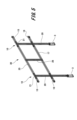
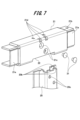
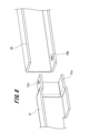
- FIG. 2 is a perspective view showing the upper handrail of the embodiment in a folded state. This is an oblique view showing the upper handrail of the embodiment in an unfolded state. An oblique view showing the upper handrail in the example embodiment with the upper rail removed. An oblique view showing a side handrail of an upper handrail in an example embodiment. An oblique view showing the upper part of the support unit in the upper handrail in an example embodiment. An oblique view showing the support and connecting portion of the support unit in the upper handrail in an example embodiment. An oblique view showing the connecting portion and intermediate upper rail of an upper handrail in an example embodiment. An oblique view showing the intermediate central rail and connecting rail in an upper handrail in an example embodiment.
- FIG. 1 is a schematic diagram showing the elevator of this embodiment.
- the elevator 100 of this example has a car 101 that moves up and down in a hoistway 201 formed in a building structure, and carries people and luggage.
- a pulley 102 for lifting the car 101 is provided at the bottom.
- the elevator 100 of this example is a so-called machine room-less elevator, which does not have a machine room at the top 202 of the hoistway 201.
- the overhead dimension will be explained.
- the length from the topmost boarding floor 205, where the car 101 stops, to the topmost part 202 of the hoistway 201 is called the overhead dimension H1.
- a foldable upper handrail 1 (see Figure 2) is used at the top of the car 101.
- devices such as the control panel and hoist installed at the topmost part 202 of the hoistway 201 come closer to the top of the car 101 during maintenance and inspection work.
- FIG. 2 and 3 are perspective views showing the upper handrail 1, with FIG. 2 showing it in a folded state and FIG. 3 showing it in an unfolded state.
- an upper handrail 1 for upper work is installed on the top of the car 101.
- the upper handrail 1 has a handrail assembly 2 and multiple pivoting support parts 3.
- the multiple pivoting support parts 3 rotatably support the handrail assembly 2.
- the handrail assembly 2 is also configured to be unfoldable from the folded state shown in Figure 2 to the unfolded state shown in Figure 3.
- the handrail assembly 2 has a number of upper rails 4, 9, 12, 15, and 25, a number of middle rails 6, 8, 13, 16, and 17, a number of posts 5, and a side handrail 30.
- An upper rail 4 is installed at the upper end in the vertical direction of the support pillar 5.
- the upper rail 4 is arranged parallel to the outer periphery of the side of the car 2.
- a middle rail 6 is installed in the vertical middle part of the support pillar 5.
- the middle rail 6 is arranged parallel to the upper rail 4.
- a connecting rail 7 is installed to connect the upper rail 4 and the middle rail 6 in the vertical direction.
- One longitudinal end of the upper rail 4 is connected to a front upper rail 12 that is disposed in front of the car 2.
- the other longitudinal end of the upper rail 4 is connected to a rear upper rail 9 that is disposed behind the car 2.
- one longitudinal end of the middle rail 6 is connected to a front middle rail 13 that is located in front of the car 2.
- the other longitudinal end of the upper rail 4 is connected to a rear middle rail 8 that is located behind the car 2.
- a rear connecting rail 11 is installed to connect the rear upper rail 9 and the rear middle rail 8 in the vertical direction.
- the upper rail 15 of the side handrail 30 is connected to the ends of the front upper rail 12 and the rear upper rail 9 opposite the upper rail 4.
- the middle rail 16 of the side handrail 30 is connected to the ends of the front middle rail 13 and the rear middle rail 8 opposite the middle rail 6.
- FIG. 4 is a perspective view showing a state in which the upper rail 25 of the side handrail 30 has been removed
- FIG. 5 is a perspective view showing the side handrail 30. As shown in FIG.
- the side handrail 30 has two upper rails 15, 15, two middle rails 16, 16, two support units 10, 10, an intermediate upper rail 25, an intermediate middle rail 17, and a connecting rail 26.
- One end of the upper rail 15 is connected to the front upper rail 12 or the rear upper rail 9.
- the other end of the upper rail 15 is connected to the support unit 10 described below.
- One end of the middle rail 16 is connected to the front middle rail 13 or the rear middle rail 8. And the other end of the middle rail 16 is connected to the support unit 10 described below.
- the support unit 10 has a support 20 and a connecting portion 21.
- the lower end of the support 20 in the vertical direction is rotatably supported by the pivot support portion 3.
- the connecting portion 21 is provided at the upper end of the support 20 in the vertical direction.
- an intermediate middle crosspiece 17 is connected to the vertical middle portion of the support 20.
- the intermediate middle crosspiece 17 is arranged so as to connect the support 20 of the two support units 10, 10.
- the intermediate middle crosspiece 17 is mechanically fastened to the support unit 10 with rivets, screws, etc., and is fixed to the support unit 10.
- an intermediate upper rail 25 is detachably connected to the connecting portion 21 of the two support units 10.
- the intermediate upper rail 25 is disposed between the support 20 of the two support units 10.
- a connecting rail 26 is disposed to connect the intermediate upper rail 25 and the intermediate middle rail 17 in the vertical direction.
- the intermediate upper rail 25 and the connecting rail 26 are configured to be removable from the side handrail 30. This makes it possible to prevent the upper handrail 1 from interfering with equipment installed at the top 202 of the elevator shaft 201 when a worker is performing inspection work. As a result, the upper handrail 1 and elevator 100 of this example can improve work efficiency during maintenance and inspection.
- Fig. 6 is a perspective view showing the upper part of the support unit 10.
- Fig. 7 is a perspective view showing the support 20 and the connecting portion 21 of the support unit 10.
- the connecting portion 21 is formed by bending a flat plate-shaped member.
- the connecting portion 21 has an engagement portion 21a, an engagement protrusion 21b, a fixing hole 21c, a locking hole 21d, and a fixing portion 21e.
- an opening 22 is formed in the connecting portion 21.
- the engaging portion 21a is formed at one longitudinal end of the connecting portion 21.
- the fixing portion 21e is formed at the other longitudinal end of the connecting portion 21 on the opposite side to the engaging portion 21a.
- the engaging portion 21a and the fixing portion 21e are each formed by Z-bending the end of the connecting portion 21.
- the bending dimensions of the engaging portion 21a and the fixing portion 21e are set to the plate thicknesses of the upper crosspiece 15 and the intermediate upper crosspiece 25, respectively.
- the corners of the bent portions of the engaging portion 21a and the fixing portion 21e are cut out.
- engaging portion 21a and the fixing portion 21e are not limited to being formed by Z-bending.
- the engaging portion 21a and the fixing portion 21e may be formed by drawing the end of the connecting portion 21.
- the upper rail 15 is fitted into the fixing portion 21e.
- the upper rail 15 is then fixed to the fixing portion 21e with rivets or the like.
- FIG. 8 is a diagram showing the state in which the connecting portion 21 and the intermediate upper rail 25 are engaged with each other.
- An engagement protrusion 21b is formed on the engagement portion 21a.
- the engagement protrusion 21b is formed by forming a slit in a part of the engagement portion 21a and bending it.
- the intermediate upper rail 25 is detachably fitted into the engagement portion 21a.
- the intermediate upper rail 25 is detachably engaged with the engagement portion 21a.
- the engaging portion 21a is Z-bent or drawn to the thickness of the intermediate upper rail 25. Therefore, when the intermediate upper rail 25 is fitted into the engaging portion 21a, the intermediate upper rail 25 and the connecting portion 21 can be made flush with each other. As a result, workers can be prevented from getting caught on the step between the intermediate upper rail 25 and the connecting portion 21 while working.
- FIG. 8 is a diagram showing the state in which the connecting portion 21 and the intermediate upper rail 25 are engaged with each other.
- the intermediate upper rail 25 is formed by bending a flat plate-like member.
- the intermediate upper rail 25 is formed of a rectangular columnar pipe with one open side. One longitudinal end of the intermediate upper rail 25 fits into the engaging portion 21a of the connecting portion 21.
- An engaging receiving portion 25b is formed on the inner wall surface of the intermediate upper rail 25.
- the engaging receiving portion 25b is a recess recessed from the inner wall surface of the intermediate upper rail 25 toward the outer wall surface.
- An engaging protrusion 21b formed on the engaging portion 21a detachably engages with the engaging receiving portion 25b.
- the intermediate upper rail 25 does not interfere with other equipment other than the top 202 of the elevator shaft 201, the intermediate upper rail 25 is attached to the connecting portion 21. At that time, by providing the engagement protrusion 21b and the engagement receiving portion 25b, the intermediate upper rail 25 can be easily positioned, and the engagement work of the intermediate upper rail 25 can be easily performed.
- the fixing hole 21c and the locking hole 21d are formed in the middle of the connecting part 21 in the longitudinal direction.
- the opening 22 is formed in the middle of the connecting part 21 in the longitudinal direction.
- the locking hole 21d is formed in the top surface of the connecting part 21 in the vertical direction and in the corner between the top surface and the front surface.
- the fixing hole 21c is formed in the front surface of the connecting part 21.
- the opening 22 is formed in the bottom surface of the connecting part 21 in the longitudinal direction. The top end of the support 20 in the vertical direction is inserted into the opening 22.
- the support 20 like the connecting portion 21 and the middle upper rail 25, is formed by bending a flat plate-like material, and is formed as a rectangular pipe with one side open.
- a locking protrusion 20b is formed at the top end of the support 20 in the vertical direction.
- a support-side fixing hole 20c is formed in the front portion of the support 20.
- the upper end of the support 20 is inserted into the opening 22 of the connecting portion 21.
- the locking projection 20b on the support 20 is locked into the locking hole 21d formed in the connecting portion 21.
- the protruding height of the locking projection 20b is set so that it is flush with the connecting portion 21 when inserted into the locking hole 21d.
- the upper end of the support 20 then abuts against the inner wall surface at the top of the connecting portion 21. This allows the support 20 to bear the load applied to the connecting portion 21.
- the post-side fixing hole 20c in the post 20 faces the fixing hole 21c in the connecting portion 21. Then, a rivet 31 is inserted into the post-side fixing hole 20c and the fixing hole 21c. This fixes the post 20 and the connecting portion 21 together.
- the support 20 is formed from a rectangular pipe member, but this is not limited to this, and the support 20 may be formed from a roughly cylindrical pipe member.
- FIG. 9 is a perspective view showing the intermediate central rail 17 and the connecting rail 26. As shown in FIG.
- the intermediate middle bar 17 and the connecting bar 26 are formed by bending a flat plate-like material, and are formed of a rectangular columnar pipe with one side open.
- An insertion port 17a is formed in the center of the intermediate middle bar 17 in the longitudinal direction.
- an engagement hole 17b is formed in the center of the intermediate middle bar 17.
- the insertion port 17a is formed in the upper surface of the intermediate middle bar 17 in the vertical direction, and the engagement hole 17b is formed in the lower surface of the intermediate middle bar 17 in the vertical direction.
- an engagement protrusion 26a is formed on the lower end of the connecting bar 26 in the vertical direction.
- the lower end of the connecting bar 26 is inserted into the insertion port 17a of the intermediate central bar 17, and the engagement protrusion 26a removably engages with the engagement hole 17b of the intermediate central bar 17.
- the protruding height of the engagement protrusion 26a is set to a height that makes it flush with the intermediate central bar 17 when inserted into the engagement hole 17b.
- the lower end of the connecting bar 26 abuts against the inner wall surface at the lower surface of the intermediate central bar 17.
- the two support units 10, the two upper rails 15, 15, and the two middle rails 16, 16 are configured as common parts with other elevators of the same type. Therefore, the dimensions and structure of the two support units 10, the two upper rails 15, 15, and the two middle rails 16, 16 do not depend on the size of the car 1.
- the middle upper rail 25 and the middle middle rail 17 are configured as non-common parts. In other words, the longitudinal lengths of the middle upper rail 25 and the middle middle rail 17 are set according to the size of the car 1.
- the upper rails, middle rails and support pillars were all formed as a single unit. Therefore, in conventional upper handrails, the upper rails, middle rails and support pillars all had to be changed depending on the size of the car 1, which resulted in poor manufacturing workability and increased costs.
- the two support units 10, the two upper rails 15, 15, and the two middle rails 16, 16 are configured as common parts with other elevators of the same type. Therefore, the dimensions and structure of the two support units 10, the two upper rails 15, 15, and the two middle rails 16, 16 do not depend on the size of the car 1.
- the middle upper rail 25 and the middle middle rail 17 are configured as non-common parts. In other words, the longitudinal lengths of the middle upper rail 25 and the middle middle rail 17 are set according to the size of the car 1.
- the area near the support pillar 20, whose dimensions and structure are not dependent on the size of the car 1, can be made into a common part, preventing a deterioration in manufacturing workability and an increase in costs.
- the intermediate middle rail 17 is fastened and fixed after being attached to the support unit 10. Therefore, even if the intermediate upper rail 25 is removed, the intermediate middle rail 17 remains positioned between the two support units 10, 10, as shown in Figure 4. This prevents the intermediate middle rail 17 from coming off during inspection work, ensuring the safety of the work.
- the upper rail 4, middle rail 6, and support post 5 arranged opposite the side handrail 30 may be configured in the same way as the side handrail 30.
- each part of the handrail assembly 2 constituting the upper handrail 1 is formed by bending a flat plate-shaped member, but this is not limited to this.
- each part of the handrail assembly 2 may be formed from a cylindrical member.
- the members can be overlapped when the handrail assembly 2 is folded, and the handrail assembly 2 can be folded compactly. As a result, it is possible to prevent the handrail assembly 2 from interfering with other equipment installed at the top of the car.
Landscapes
- Engineering & Computer Science (AREA)
- Civil Engineering (AREA)
- Mechanical Engineering (AREA)
- Structural Engineering (AREA)
- Cage And Drive Apparatuses For Elevators (AREA)
Priority Applications (3)
| Application Number | Priority Date | Filing Date | Title |
|---|---|---|---|
| PCT/JP2023/006979 WO2024180586A1 (ja) | 2023-02-27 | 2023-02-27 | 乗りかごの上部手すり及びエレベーター |
| CN202380081520.7A CN120187662A (zh) | 2023-02-27 | 2023-02-27 | 电梯轿厢的上部扶栏以及电梯 |
| JP2025503222A JPWO2024180586A1 (https=) | 2023-02-27 | 2023-02-27 |
Applications Claiming Priority (1)
| Application Number | Priority Date | Filing Date | Title |
|---|---|---|---|
| PCT/JP2023/006979 WO2024180586A1 (ja) | 2023-02-27 | 2023-02-27 | 乗りかごの上部手すり及びエレベーター |
Publications (1)
| Publication Number | Publication Date |
|---|---|
| WO2024180586A1 true WO2024180586A1 (ja) | 2024-09-06 |
Family
ID=92589444
Family Applications (1)
| Application Number | Title | Priority Date | Filing Date |
|---|---|---|---|
| PCT/JP2023/006979 Ceased WO2024180586A1 (ja) | 2023-02-27 | 2023-02-27 | 乗りかごの上部手すり及びエレベーター |
Country Status (3)
| Country | Link |
|---|---|
| JP (1) | JPWO2024180586A1 (https=) |
| CN (1) | CN120187662A (https=) |
| WO (1) | WO2024180586A1 (https=) |
Citations (6)
| Publication number | Priority date | Publication date | Assignee | Title |
|---|---|---|---|---|
| JP2005041650A (ja) * | 2003-07-22 | 2005-02-17 | Mitsubishi Electric Corp | 展望用エレベータのかご室上部作業台 |
| JP2005532966A (ja) * | 2002-06-20 | 2005-11-04 | オーチス エレベータ カンパニー | 機械室レス型エレベータのかご用の上部安全柵 |
| JP2011093618A (ja) * | 2009-10-27 | 2011-05-12 | Mitsubishi Electric Corp | エレベータのかご上手摺装置 |
| US20180002139A1 (en) * | 2016-06-29 | 2018-01-04 | Otis Elevator Company | Adjustable handrail system for a top of an elevator car and method of adjusting |
| JP2019199339A (ja) * | 2018-05-17 | 2019-11-21 | 三菱電機ビルテクノサービス株式会社 | エレベーターのかご上安全柵 |
| KR20200025780A (ko) * | 2018-08-31 | 2020-03-10 | 이금기 | 엘리베이터 상부용 안전난간 |
-
2023
- 2023-02-27 CN CN202380081520.7A patent/CN120187662A/zh active Pending
- 2023-02-27 JP JP2025503222A patent/JPWO2024180586A1/ja active Pending
- 2023-02-27 WO PCT/JP2023/006979 patent/WO2024180586A1/ja not_active Ceased
Patent Citations (6)
| Publication number | Priority date | Publication date | Assignee | Title |
|---|---|---|---|---|
| JP2005532966A (ja) * | 2002-06-20 | 2005-11-04 | オーチス エレベータ カンパニー | 機械室レス型エレベータのかご用の上部安全柵 |
| JP2005041650A (ja) * | 2003-07-22 | 2005-02-17 | Mitsubishi Electric Corp | 展望用エレベータのかご室上部作業台 |
| JP2011093618A (ja) * | 2009-10-27 | 2011-05-12 | Mitsubishi Electric Corp | エレベータのかご上手摺装置 |
| US20180002139A1 (en) * | 2016-06-29 | 2018-01-04 | Otis Elevator Company | Adjustable handrail system for a top of an elevator car and method of adjusting |
| JP2019199339A (ja) * | 2018-05-17 | 2019-11-21 | 三菱電機ビルテクノサービス株式会社 | エレベーターのかご上安全柵 |
| KR20200025780A (ko) * | 2018-08-31 | 2020-03-10 | 이금기 | 엘리베이터 상부용 안전난간 |
Also Published As
| Publication number | Publication date |
|---|---|
| JPWO2024180586A1 (https=) | 2024-09-06 |
| CN120187662A (zh) | 2025-06-20 |
Similar Documents
| Publication | Publication Date | Title |
|---|---|---|
| US8646576B2 (en) | Foldable hoistway work deck | |
| JP2000328777A (ja) | エレベータ据付用足場構造 | |
| KR102536340B1 (ko) | 엘리베이터 설치용 시스템 비계 | |
| CN111634786A (zh) | 用于电梯轿厢的工作平台 | |
| JP6227153B2 (ja) | 天井ユニットおよび天井ユニットを備えたエレベーターのかご | |
| KR102373661B1 (ko) | 엘리베이터 설치용 비계장치 | |
| KR20040010787A (ko) | 엘리베이터 카의 상부난간 | |
| JP2003321174A (ja) | エレベータ乗り籠の作業用柵 | |
| CN101031494B (zh) | 电梯的轿厢上扶手装置 | |
| JPWO2003020629A1 (ja) | 乗りかご及びエレベータ装置 | |
| JP2009057198A (ja) | エレベータかご、エレベータかごの組立方法、および揚重治具 | |
| US20050230194A1 (en) | Safety fence at upper part of cab | |
| WO2024180586A1 (ja) | 乗りかごの上部手すり及びエレベーター | |
| US11554935B2 (en) | Elevator car | |
| JPH05340085A (ja) | 昇降路作業用足場装置 | |
| JP2002046951A (ja) | エレベーターの保守用足場装置 | |
| JP7803788B2 (ja) | 追加手すり及びエレベーター | |
| WO2019176105A1 (ja) | エレベータのかご天井装置 | |
| EP4353644A1 (en) | Handrail and elevator | |
| JP2023107328A (ja) | 移動範囲規制ブラケット及びエレベーター | |
| JP7583224B2 (ja) | 巻上機据付ガイド装置及び巻上機の据付方法 | |
| WO2003104130A1 (ja) | エレベータ装置 | |
| JP5972161B2 (ja) | エレベーター装置 | |
| JP2024167976A (ja) | 乗りかごの上部手すり及びエレベーター | |
| CN111655603B (zh) | 电梯用作业台及电梯 |
Legal Events
| Date | Code | Title | Description |
|---|---|---|---|
| 121 | Ep: the epo has been informed by wipo that ep was designated in this application |
Ref document number: 23925144 Country of ref document: EP Kind code of ref document: A1 |
|
| WWE | Wipo information: entry into national phase |
Ref document number: 2025503222 Country of ref document: JP |
|
| WWE | Wipo information: entry into national phase |
Ref document number: 202380081520.7 Country of ref document: CN |
|
| WWP | Wipo information: published in national office |
Ref document number: 202380081520.7 Country of ref document: CN |
|
| NENP | Non-entry into the national phase |
Ref country code: DE |
|
| 122 | Ep: pct application non-entry in european phase |
Ref document number: 23925144 Country of ref document: EP Kind code of ref document: A1 |