WO2024176409A1 - 同期機制御装置 - Google Patents
同期機制御装置 Download PDFInfo
- Publication number
- WO2024176409A1 WO2024176409A1 PCT/JP2023/006578 JP2023006578W WO2024176409A1 WO 2024176409 A1 WO2024176409 A1 WO 2024176409A1 JP 2023006578 W JP2023006578 W JP 2023006578W WO 2024176409 A1 WO2024176409 A1 WO 2024176409A1
- Authority
- WO
- WIPO (PCT)
- Prior art keywords
- magnetic flux
- synchronous machine
- axis
- value
- control device
- Prior art date
- Legal status (The legal status is an assumption and is not a legal conclusion. Google has not performed a legal analysis and makes no representation as to the accuracy of the status listed.)
- Ceased
Links
Images



Classifications
-
- H—ELECTRICITY
- H02—GENERATION; CONVERSION OR DISTRIBUTION OF ELECTRIC POWER
- H02P—CONTROL OR REGULATION OF ELECTRIC MOTORS, ELECTRIC GENERATORS OR DYNAMO-ELECTRIC CONVERTERS; CONTROLLING TRANSFORMERS, REACTORS OR CHOKE COILS
- H02P3/00—Arrangements for stopping or slowing electric motors, generators, or dynamo-electric converters
- H02P3/06—Arrangements for stopping or slowing electric motors, generators, or dynamo-electric converters for stopping or slowing an individual dynamo-electric motor or dynamo-electric converter
- H02P3/18—Arrangements for stopping or slowing electric motors, generators, or dynamo-electric converters for stopping or slowing an individual dynamo-electric motor or dynamo-electric converter for stopping or slowing an AC motor
- H02P3/22—Arrangements for stopping or slowing electric motors, generators, or dynamo-electric converters for stopping or slowing an individual dynamo-electric motor or dynamo-electric converter for stopping or slowing an AC motor by short-circuit or resistive braking
-
- H—ELECTRICITY
- H02—GENERATION; CONVERSION OR DISTRIBUTION OF ELECTRIC POWER
- H02P—CONTROL OR REGULATION OF ELECTRIC MOTORS, ELECTRIC GENERATORS OR DYNAMO-ELECTRIC CONVERTERS; CONTROLLING TRANSFORMERS, REACTORS OR CHOKE COILS
- H02P21/00—Arrangements or methods for the control of electric machines by vector control, e.g. by control of field orientation
- H02P21/14—Estimation or adaptation of machine parameters, e.g. flux, current or voltage
- H02P21/141—Flux estimation
-
- H—ELECTRICITY
- H02—GENERATION; CONVERSION OR DISTRIBUTION OF ELECTRIC POWER
- H02P—CONTROL OR REGULATION OF ELECTRIC MOTORS, ELECTRIC GENERATORS OR DYNAMO-ELECTRIC CONVERTERS; CONTROLLING TRANSFORMERS, REACTORS OR CHOKE COILS
- H02P21/00—Arrangements or methods for the control of electric machines by vector control, e.g. by control of field orientation
- H02P21/22—Current control, e.g. using a current control loop
Definitions
- the present invention relates to a synchronous machine control device for driving a synchronous machine such as a synchronous motor.
- the control device described in Patent Document 1 is known as a control device that can improve the performance of a motor.
- a first magnetic flux command value is calculated from a current command value of a synchronous machine
- a magnetic flux value of the synchronous machine is estimated from a current detection value of the synchronous machine
- a voltage command value of a power converter is created so that the first magnetic flux command value and the magnetic flux value match.
- an adder/subtractor calculates the difference between the first d-axis magnetic flux command value and the d-axis magnetic flux estimated value.
- the calculated difference value is integrated by an integrator, and the integral value is multiplied by an integral gain (KI).
- the calculated difference value multiplied by the proportional gain 97 and the integral value multiplied by the integral gain are added by an adder 99 to calculate a second d-axis magnetic flux command value.
- the second q-axis magnetic flux command value is also calculated in a similar manner.
- the present invention was made in consideration of these problems, and aims to provide a synchronous machine control device that suppresses overcurrent and torque fluctuations when switching from three-phase open or short-circuit mode to torque mode (PWM mode).
- PWM mode torque mode
- the synchronous machine control device is a synchronous machine control device that controls a power converter that supplies power to a synchronous machine, and includes a first flux command calculation unit that calculates a first flux command value from a current command value of the synchronous machine, a flux estimation unit that estimates a flux value of the synchronous machine from a current detection value of the synchronous machine, and a second flux command calculation unit that uses an integral controller to calculate a second flux command value so that the first flux command value and the flux value match, and the integral controller is initialized with the d-axis flux value on the d-axis side and the q-axis flux value on the q-axis side when the power converter switches from three-phase short circuit to PWM control.
- the present invention makes it possible to suppress overcurrent and torque fluctuations when switching from three-phase open or short circuit mode to torque mode (PWM mode).
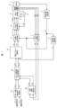
- FIG. 1 is a block diagram showing a functional configuration of a synchronous machine control device according to an embodiment
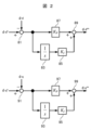
- 4 is a block diagram showing a functional configuration of a PI controller in a second dq-axis magnetic flux command calculation unit 25.
- FIG. 2 shows the configuration of a voltage vector calculation unit 19 configured based on the inverse model expressed by equation (1). An example of the relationship between magnetic flux and current is shown below.
- FIG. 2 is a block diagram showing a configuration of an integrator according to the embodiment.
- FIG. 13 is a block diagram showing a configuration of an integrator according to a modified example of the embodiment.
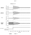
- FIG. 13 is a diagram showing current waveforms when switching from a three-phase short circuit mode to a PWM mode in conventional control.
- FIG. 1 is a block diagram showing a functional configuration of a synchronous machine control device according to an embodiment
- 4 is a block diagram showing a functional configuration of a PI controller in a second dq-axis magnetic flux command calculation unit 25.
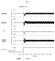
- FIG. 13 is a diagram showing current waveforms when switching from a three-phase short circuit mode to a PWM mode in the control according to the embodiment.
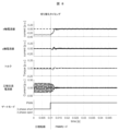
- FIG. 13 is a diagram showing current waveforms when switching from three-phase open mode to PWM mode in conventional control.
- FIG. 13 is a diagram showing current waveforms when switching from three-phase open mode to PWM mode in the control according to the embodiment.
- the synchronous machine to be controlled is a permanent magnet synchronous motor (hereinafter referred to as "PMSM” (short for Permanent Magnet Synchronous Motor)).
- PMSM permanent magnet synchronous motor
- FIG. 1 is a block diagram showing the functional configuration of a synchronous machine control device according to this embodiment.
- a computer system such as a microcomputer executes a predetermined program to function as the synchronous machine control device shown in Fig. 1.
- the power converter 2 converts DC power from a DC voltage source 9 (e.g., a battery) into AC power and outputs it to the PMSM 1.
- the PMSM 1 is driven to rotate by this AC power.
- the power converter 2 includes an inverter main circuit made up of semiconductor switching elements.
- the DC power is converted into AC power by controlling the semiconductor switching elements to be turned on and off by a gate signal.
- an IGBT Insulated Gate Bipolar Transistor
- the phase current detector 3 detects the three-phase motor currents flowing from the power converter 2 to the PMSM 1, i.e., the U-phase current Iu, the V-phase current Iv, and the W-phase current Iw, and outputs them as the U-phase current detection value Iuc, the V-phase current detection value Ivc, and the W-phase current detection value Iwc, respectively.
- a Hall CT Current Transformer
- the magnetic pole position detector 4 detects the magnetic pole position of the PMSM 1 and outputs magnetic pole position information ⁇ * .
- a resolver or the like is used as the magnetic pole position detector 4.
- the frequency calculation unit 5 calculates and outputs speed information ⁇ 1 * from the magnetic pole position information ⁇ * output by the magnetic pole position detector 4 by performing a time differentiation operation or the like.
- the coordinate conversion unit 7 converts the Iuc, Ivc, and Iwc output by the phase current detector into d-axis and q-axis current detection values Idc and Iqc in a rotating coordinate system according to the magnetic pole position information ⁇ * , and outputs Idc and Iqc.
- the dq-axis magnetic flux estimation unit 23 estimates the dq-axis magnetic flux estimation values ⁇ dc, ⁇ qc by referring to a lookup table (table data) based on the dq-axis current detection values Idc, Iqc output by the coordinate conversion unit 7.
- the lookup table (table data) referred to by the dq-axis magnetic flux estimation unit 23 is table data showing the correspondence between Idc, Iqc and ⁇ dc, ⁇ qc, and is stored in a storage device (not shown) provided in the synchronous machine control device of this embodiment. Note that a predetermined function (approximation formula, etc.) may be used instead of the lookup table.
- the first dq-axis magnetic flux command calculation unit 21 refers to a lookup table (table data) based on the dq-axis current command values Idc * , Iqc * provided from a higher-level control device, and calculates and outputs the first dq-axis magnetic flux command values ⁇ d * , ⁇ q * .
- the lookup table (table data) referred to by the first dq-axis magnetic flux command calculation unit 21 is table data showing the correspondence between Idc * , Iqc * and ⁇ d * , ⁇ q *, and is stored in a storage device (not shown) provided in the synchronous machine control device of this embodiment. Note that a predetermined function (approximation formula, etc.) may be used instead of the lookup table.
- the second dq-axis magnetic flux command calculation unit 25 calculates and outputs second dq-axis magnetic flux command values ⁇ d ** , ⁇ q ** using a proportional-integral (PI) controller so that the first dq-axis magnetic flux command values ⁇ d * , ⁇ q * and the dq-axis magnetic flux estimated values ⁇ dc, ⁇ qc coincide with each other.
- PI proportional-integral
- FIG. 2 is a block diagram showing the functional configuration of a PI controller in the second dq-axis magnetic flux command calculation unit 25.
- an adder/subtractor 81 calculates the difference ( ⁇ d * - ⁇ dc) between the first d-axis magnetic flux command value ⁇ d * and the d-axis magnetic flux estimated value ⁇ dc, and multiplies the calculated difference by a proportional gain 87 (K P ).
- an integrator 83 integrates the calculated difference, and the integral value is multiplied by an integral gain 85 (K I ).
- An adder 89 adds the calculated difference multiplied by the proportional gain 87 and the integral value multiplied by the integral gain 85 to calculate the second d-axis magnetic flux command value ⁇ d ** .
- an adder/subtractor 91 calculates the difference ( ⁇ q * - ⁇ qc) between the first q-axis magnetic flux command value ⁇ q * and the q-axis magnetic flux estimated value ⁇ qc, and multiplies the calculated difference by a proportional gain 97 ( KP ).
- an integrator 93 integrates the calculated difference, and the integral value is multiplied by an integral gain 95 (KI).
- An adder 99 adds the calculated difference multiplied by the proportional gain 97 and the integral value multiplied by the integral gain 95 to calculate the second d-axis magnetic flux command value ⁇ q ** .
- the voltage vector calculation unit 19 shown in FIG. 1 creates a voltage command value by an inverse model of the motor model.
- the inverse model of the motor model is expressed by a voltage equation such as, for example, equation ( 1), where the d-axis magnetic flux and q-axis magnetic flux of the motor are ⁇ d and ⁇ q, the d-axis voltage and q-axis voltage of the motor are Vd and Vq, and the motor speed is ⁇ 1 .
- Vd and Vd are the d-axis voltage command value Vd * and the q-axis voltage command value Vq * , respectively
- ⁇ d and ⁇ q are the second d-axis magnetic flux command value ⁇ d ** and the second q-axis magnetic flux command value ⁇ q ** , respectively
- ⁇ 1 is the speed information ⁇ 1 * .
- equation (1) takes into account the magnetic saturation of the motor.
- Figure 3 shows the configuration of the voltage vector calculation unit 19, which is configured based on the inverse model expressed by equation (1).
- R, Ld, Lq, and Ke are the winding resistance, d-axis inductance, q-axis inductance, and magnet magnetic flux in PMSM1, respectively.
- a differentiator 45 calculates the differentiation of ⁇ d ** .
- An adder-subtractor 44 calculates the difference between ⁇ d ** and Ke ( ⁇ d ** - Ke), and this difference calculation value is multiplied by R/Ld (46).
- An adder 47 adds the differentiation calculation value by the differentiator 45 and the difference calculation value multiplied by the gain R/Ld (46).
- a multiplier 48 multiplies ⁇ 1 * by ⁇ q ** .
- An adder-subtractor 49 calculates the difference between the addition calculation value by the adder 47 and the multiplication value by the multiplier 48 to create Vd * .
- a differentiator 35 differentiates ⁇ q ** .
- ⁇ q ** is multiplied by R/Lq (36).
- the differential value by the differentiator 35 and ⁇ q** multiplied by R/Lq (36) are added by an adder 37.
- a multiplier 38 multiplies ⁇ 1 * by ⁇ d ** .
- An adder 39 adds the sum by the adder 37 and the multiplied value by the multiplier 38 to generate Vq * .
- a voltage vector calculation unit can be constructed based on the voltage equation that represents the inverse model of the motor model.
- the coordinate conversion unit 11 shown in Figure 1 creates and outputs three-phase voltage command values Vu*, Vv * , Vw * for the power converter 2 by coordinate converting the dq-axis voltage command values Vd * , Vq * for the power converter 2 output by the voltage vector calculation unit 19 using the magnetic pole position information ⁇ * detected by the magnetic pole position detector 4 .
- the DC voltage detector 6 detects the voltage of the DC voltage source 9 and outputs DC voltage information Vdc.
- the PWM controller 12 receives the three-phase voltage command values Vu * , Vv * , Vw * from the voltage vector calculation unit 19 and also receives DC voltage information Vdc from the DC voltage detector 6, and based on these, creates and outputs a gate signal to be given to the power converter 2 by pulse width modulation.
- the PWM controller 12 uses, for example, a triangular wave as a carrier signal and creates the gate signal by pulse width modulation with the three-phase voltage command value as a modulating wave.
- Ldh, Lqh, Ldqh, and Lqdh represent dynamic inductances
- Ld, Lq, Ldq, and Lqd represent static inductances
- Figure 4 shows an example of the relationship between magnetic flux and current. Note that the vertical and horizontal axes are the solid lines in the diagram showing the relationship between magnetic flux and current.
- Dynamic inductance Lqh is the slope (d ⁇ q/dt) of the tangent (dashed line in the figure) at a certain operating point (Iq, ⁇ q).
- Static inductance Lq is the slope ( ⁇ q/Iq) of the straight line (dashed line in the figure) connecting the point where the q-axis current (Iq) is 0 and the operating point.
- equation (2) the coefficient (matrix) in the current differential term (second term on the right-hand side) is the dynamic inductance, and the coefficient (matrix) in the induced voltage term (third term on the right-hand side) is the static inductance.
- the synchronous machine control device When controlling PMSM1 based on equation (2), i.e., with the current as the state quantity and taking magnetic saturation into consideration, the above-mentioned eight types of inductance (Ldh, Lqh, Ldqh, Lqdh, Ld, Lq, Ldq, Lqd) are used. Therefore, in this case, the synchronous machine control device will have eight table data or functions (approximation formulas, etc.) that represent the correspondence between each inductance value and the current value (d-axis current value and q-axis current value).
- each of the table data or formulas becomes table data or a function of three variables, with the d-axis current value, the q-axis current value, and temperature as variables.
- the synchronous machine control device will have one two-variable table data or function (approximation formula, etc.) that expresses the relationship between the two variables, Iq and T, and Ke.
- the synchronous machine control device when controlling PMSM1 with the current as the state quantity and taking into account magnetic saturation, the synchronous machine control device will be equipped with multiple multivariable table data or multivariable functions.
- the total number of table data or functions (approximation expressions, etc.) used in the synchronous machine control device (9 when the current is used as the state quantity as described above) is reduced while still taking magnetic saturation into account.
- the winding resistance R is sufficiently small, so the effect of the first term in equation (3) on motor control is relatively small. Therefore, even if equation (1) is approximated and Ld, Lq, and Ke are set to constant values, the effect on motor control is small. Therefore, the voltage vector calculation unit 19 in this embodiment creates d-axis and q-axis voltage command values (Vd*, Vq*) according to d-axis and q-axis magnetic flux command values ( ⁇ d ** , ⁇ q ** ) based on the above equation (1) in which the magnetic flux is a state quantity, and by setting Ld, Lq, and Ke in equation ( 1 ) to constant values.
- the synchronous machine control device has table data or functions (approximation expressions, etc.) that represent the correspondence between the d-axis magnetic flux ( ⁇ d) and the q-axis magnetic flux ( ⁇ q) and the currents (d-axis current Id, q-axis current Iq). Therefore, the synchronous machine control device has a total of two table data or functions.
- the dq-axis voltage command values Vd*, Vq * are generated based on the second dq-axis flux command values ⁇ d ** , ⁇ q ** generated by the second dq-axis flux command calculation unit 25 using an inverse model of the motor model. Therefore, even in the high-speed region, the d-axis flux estimate value ⁇ dc and the q-axis flux estimate value ⁇ qc can be made to match the second d-axis flux command value ⁇ d ** and the second q-axis flux command value ⁇ q ** with high accuracy. Therefore, the synchronous machine control device according to this embodiment makes it possible to control the high-speed rotation of the PMSM1.
- the effect of the temperature dependency of the magnetic flux is mitigated by the PI controller or I controller provided in the second dq-axis magnetic flux command calculation unit 25.
- the table data or function used to calculate the magnetic flux ( ⁇ d, ⁇ q) may be table data or a function (such as an approximate formula) that does not include temperature as a variable and has only the current as a variable. This can reduce the calculation load of the synchronous machine control device and shorten the parameter identification time.
- Idc and Iqc are controlled so as to coincide with Id * and Iq * , respectively, via the magnetic flux, so to speak.
- a current control system is essentially configured.
- control that takes into consideration mutual interference between the axes becomes possible by using both Idc, Iqc and Id * , Iq * as inputs to the first dq-axis magnetic flux command calculation unit 21 and the dq-axis magnetic flux estimation unit 23.
- the first dq-axis magnetic flux command calculation unit 21 and the dq-axis magnetic flux estimation unit 23 use table data or functions that represent the correspondence between the dq-axis magnetic flux command values ( ⁇ d * , ⁇ q * ) and the dq-axis current command values (Id * , Iq * ) and table data or functions that represent the correspondence between the dq-axis magnetic flux estimation values ( ⁇ dc, ⁇ qc) and the dq-axis current detection values (Idc, Iqc), respectively.
- the synchronous machine control device of this embodiment takes into account the dynamic inductance and static inductance of the motor, making it suitable for application to electric vehicles and other electric vehicles that use PMSMs, which are significantly affected by magnetic saturation, and require accurate torque response.
- lookup table, table data, and functions which are information that represents the correspondence between magnetic flux and current in PMSM1, can be set based on actual measurements, magnetic field analysis, etc.
- Figure 7 shows the current waveforms when switching from three-phase short circuit to PWM mode in conventional control. It shows the waveforms of the d-axis current, q-axis current, torque, and three-phase AC current as well as the gate mode switching signal when the integrator 83 on the d-axis side is initialized to magnet flux Ke and the integrator 93 on the q-axis side is initialized to 0.
- the dotted lines in Figure 7 show the timing of switching from three-phase short circuit to PWM mode in the power converter 2.
- FIG. 5 is a block diagram of an integrator according to this embodiment.
- the integrator 83 receives a gate mode switching signal when the drive state (gate mode) of the power converter 2 is switched from a higher-level controller (not shown) or the like.
- the d-axis magnetic flux estimate ⁇ dc is used as the initial value for the integrator 83 on the d-axis side.
- the q-axis magnetic flux estimate ⁇ qc is used as the initial value for the integrator 93 on the q-axis side.
- values obtained by applying low-pass filter processing to the d-axis magnetic flux estimate ⁇ dc and the q-axis magnetic flux estimate ⁇ qc may be used as the initial values.
- the integral value on the d-axis side coincides with the d-axis magnetic flux estimate ⁇ dc.
- the integral value on the q-axis side coincides with the q-axis magnetic flux estimate ⁇ qc. Therefore, by initializing the integrator 83 on the d-axis side with the d-axis magnetic flux estimate ⁇ dc and the integrator 93 on the q-axis side with the q-axis magnetic flux estimate ⁇ qc, the voltage of the PMSM1 and the voltage of the power converter 2 coincide, and the change in current at the time of switching can be suppressed.
- the power converter 2 when the power converter 2 is in a three-phase short circuit, the voltage becomes 0V and a current flows in the PMSM1 such that the voltage becomes 0V. Therefore, when the power converter 2 transitions from a three-phase short circuit to PWM mode, it is sufficient to output a voltage that causes the current that flows during the three-phase short circuit to flow.
- the integrator 83 on the d-axis side with the d-axis magnetic flux estimate value ⁇ dc and the integrator 93 on the q-axis side with the q-axis magnetic flux estimate value ⁇ qc the voltage of the PMSM1 and the voltage of the power converter 2 match, and the change in current at the time of switching can be suppressed.
- Figure 8 shows the change in current when switching from three-phase short circuit to PWM mode in the control according to this embodiment. It shows the waveforms of the d-axis current, q-axis current, torque, and three-phase AC current, as well as the gate mode switching signal, when the integrator 83 on the d-axis side is initialized with the d-axis magnetic flux estimate value ⁇ dc, and the integrator 93 on the q-axis side is initialized with the q-axis magnetic flux estimate value ⁇ qc.
- the control device according to this embodiment suppresses the changes in the d-axis current and q-axis current after switching of the power converter 2. This makes it possible to suppress the occurrence of overcurrent.
- the integrator 83 on the d-axis side is initialized with the d-axis magnetic flux estimate value ⁇ dc
- the integrator 93 on the q-axis side 0. This makes it possible to suppress the occurrence of overcurrent even when transitioning from three-phase short circuit to PWM mode.
- FIG. 6 is a diagram showing an integrator according to a modified example of this embodiment.
- the value initialized to the integrator 183 on the d-axis side is configured to differ depending on the state before the drive mode of the power converter 2 is switched. This makes it possible to initialize the integrator 183 with an appropriate value depending on the state before the drive mode of the power converter 2 is switched.
- the drive state before switching the power converter 2 when the drive state before switching the power converter 2 is three-phase open, it is initialized with the magnet flux Ke considering the rotor temperature, and when the drive state before switching the power converter 2 is three-phase short circuit, it is initialized with the d-axis magnetic flux estimated value ⁇ dc.
- the d-axis magnetic flux estimated value ⁇ dc changes depending on the rotor temperature of the PMSM1, so by using the magnet flux Ke considering the rotor temperature, more accurate control is possible.
- the reason why the rotor temperature is considered only in the three-phase open is that in automobiles and the like, three-phase open is actively used during operation to reduce losses.
- Figure 9 shows the current waveforms when switching from three-phase open to PWM mode in conventional control. It shows the time variations of the d-axis current, q-axis current, torque, and three-phase AC current, as well as the gate mode switching signal, when the integrator 83 on the d-axis side is initialized to magnet flux Ke that does not take into account rotor temperature, and the integrator 93 on the q-axis side is initialized to 0.
- the dotted lines in Figure 9 show the timing of switching from three-phase open to PWM mode in the power converter 2.
- the control device according to this embodiment suppresses the changes in the d-axis current and q-axis current after switching the power converter 2. This makes it possible to suppress the occurrence of deterioration in ride comfort due to sudden torque fluctuations.
- the dq-axis magnetic flux estimation unit 23 may be configured to estimate the magnetic flux values of the d and q axes of the PMSM1 based on a three-dimensional table that takes into account the rotor temperature of the PMSM1. Although this increases the amount of motor adaptation work, it allows the rotor temperature to be taken into account, making it possible to more accurately prevent overcurrent and torque fluctuations caused by changes in the driving state of the power converter 2.
- the integrator may be initialized with the rotor temperature set to a predetermined value. This makes it possible to prevent overcurrent and torque fluctuations caused by changes in the driving state of the power converter 2, even if the rotor temperature cannot be obtained.
- a synchronous machine control device that controls a power converter that supplies power to a synchronous machine, the control device comprising: a first flux command calculation unit that calculates a first flux command value from a current command value of the synchronous machine; a flux estimation unit that estimates d-axis and q-axis flux values of the synchronous machine from a current detection value of the synchronous machine; a voltage calculation unit that creates a voltage command value for the power converter so that the first flux command value and the flux value match; and a second flux command calculation unit that uses an integrator to calculate second flux command values on the d-axis side and the q-axis side, respectively, so that the first flux command value and the flux value match.
- the integrator When the driving state of the power converter is switched, the integrator is initialized with the d-axis flux value on the d-axis side and the q-axis flux value on the q-axis side. This makes it possible to prevent overcurrents and the like caused by changes in the driving state of the power converter.
- the integral controller may be configured so that when the driving state of the power converter is switched, the value initialized differs depending on the driving state before the switch. This allows the integrator to be initialized with an appropriate value, making it possible to more accurately prevent torque fluctuations and the like caused by changes in the driving state of the power converter.
- the d-axis side may be initialized to a value determined based on the temperature of the rotor of the synchronous machine. This makes it possible to prevent deterioration of ride comfort caused by sudden torque fluctuations when the power conversion device switches from three-phase open to PWM mode.
- the d-axis side is initialized with the d-axis magnetic flux value and the q-axis side with the q-axis magnetic flux value
- the d-axis side is initialized with the magnet magnetic flux Ke that takes into account the rotor temperature of the synchronous machine
- the q-axis side is initialized with the q-axis magnetic flux value.
- the magnetic flux estimation unit may be configured to estimate the magnetic flux values of the d-axis and q-axis of the synchronous machine based on a three-dimensional table that takes into account the rotor temperature of the synchronous machine. This allows the rotor temperature to be taken into account, making it possible to more accurately prevent overcurrents and torque fluctuations caused by changes in the driving state of the power converter.
- the integrator may be initialized with the rotor temperature set to a predetermined value. This makes it possible to prevent overcurrent and torque fluctuations caused by changes in the driving state of the power converter, even if the rotor temperature cannot be obtained.
- the present invention is not limited to the above-described embodiments, but includes various modified examples.
- the above-described embodiments have been described in detail to clearly explain the present invention, and the present invention is not necessarily limited to those having all of the configurations described.
- the synchronous machine to be controlled is not limited to a PMSM, but may be a synchronous reluctance motor, a permanent magnet synchronous generator, a wound field type synchronous motor, a wound field type synchronous generator, etc.
- the PMSM may be either an embedded magnet type or a surface magnet type, and may be either an abductor type or an adductor type.
- the semiconductor switching elements that make up the inverter main circuit are not limited to IGBTs, but may be MOSFETs (Metal Oxide Semiconductor Field Effect Transistors) or the like.
- the synchronous machine control device can be applied as this control device in various synchronous machine drive systems that include a synchronous machine, a power converter that drives the synchronous machine, and a control device that controls the power converter.
Landscapes
- Engineering & Computer Science (AREA)
- Power Engineering (AREA)
- Control Of Ac Motors In General (AREA)
Abstract
Description
図1は、本実施形態に係る同期機制御装置の機能構成を示すブロック図である。なお、本実施形態においては、マイクロコンピュータなどのコンピュータシステムが、所定のプログラムを実行することにより、図1に示す同期機制御装置として機能する。
図2は、第二dq軸磁束指令演算部25におけるPI制御器の機能構成を示すブロック図である。
図1に示す電圧ベクトル演算部19は、モータモデルの逆モデルによって、電圧指令値を作成する。

以下、本実施形態の電圧ベクトル演算部19に用いられる、PMSM1の磁気飽和を考慮した電圧指令値の作成手段について説明する。


次に、本実施形態に係る積分器の初期化について、図5から図8を用いて説明する。
次に図6を用いて本実施形態の変形例を説明する。図6は、本実施形態の変形例に係る積分器を示した図である。
Claims (6)
- 同期機に電力を供給する電力変換器を制御する同期機制御装置であって、
前記同期機の電流指令値から第一磁束指令値を演算する第一磁束指令演算部と、
前記同期機の電流検出値から前記同期機のd軸及びq軸の磁束値を推定する磁束推定部と、
前記第一磁束指令値と前記磁束値が一致するように前記電力変換器の電圧指令値を作成する電圧演算部と、
積分制御器を用いて、前記第一磁束指令値と前記磁束値が一致するようにd軸側及びq軸側の第二磁束指令値をそれぞれ演算する第二磁束指令演算部と、を備え、
前記積分制御器は、前記電力変換器の駆動状態が切り変わるときに、
前記d軸側がd軸磁束値、前記q軸側がq軸磁束値で初期化されることを特徴とする同期機制御装置。 - 請求項1に記載の同期機制御装置であって、
前記積分制御器は、前記電力変換器の駆動状態が切り変わるときに、切り替わり前の駆動状態により初期化される値が異なることを特徴とする同期機制御装置。 - 請求項2に記載の同期機制御装置であって、
前記切り替わり前の駆動状態が三相開放のときは、前記d軸側が磁石磁束で初期化されることを特徴とする同期機制御装置。 - 請求項2に記載の同期機制御装置であって、
前記切り替わり前の駆動状態が三相短絡のときは、前記d軸側がd軸磁束値、前記q軸側がq軸磁束値で初期化され、
前記切り替わり前の駆動状態が三相開放のときは、前記d軸側が前記同期機のロータの温度を考慮した磁石磁束、前記q軸側がq軸磁束値で初期化されることを特徴とする同期機制御装置。 - 請求項1に記載の同期機制御装置であって、
前記磁束推定部は、前記同期機のロータ温度を考慮した3次元テーブルに基づき、
前記同期機のd軸及びq軸の磁束値を推定することを特徴とする同期機制御装置。 - 請求項4または5に記載の同期機制御装置であって、
前記ロータ温度情報が取得できない場合、前記ロータ温度が所定値として前記積分制御器を初期化することを特徴とする同期機制御装置。
Priority Applications (4)
| Application Number | Priority Date | Filing Date | Title |
|---|---|---|---|
| CN202380091827.5A CN120569894A (zh) | 2023-02-22 | 2023-02-22 | 同步机控制装置 |
| JP2025502030A JPWO2024176409A1 (ja) | 2023-02-22 | 2023-02-22 | |
| DE112023004830.4T DE112023004830T5 (de) | 2023-02-22 | 2023-02-22 | Steuervorrichtung für eine synchronmaschine |
| PCT/JP2023/006578 WO2024176409A1 (ja) | 2023-02-22 | 2023-02-22 | 同期機制御装置 |
Applications Claiming Priority (1)
| Application Number | Priority Date | Filing Date | Title |
|---|---|---|---|
| PCT/JP2023/006578 WO2024176409A1 (ja) | 2023-02-22 | 2023-02-22 | 同期機制御装置 |
Publications (1)
| Publication Number | Publication Date |
|---|---|
| WO2024176409A1 true WO2024176409A1 (ja) | 2024-08-29 |
Family
ID=92500443
Family Applications (1)
| Application Number | Title | Priority Date | Filing Date |
|---|---|---|---|
| PCT/JP2023/006578 Ceased WO2024176409A1 (ja) | 2023-02-22 | 2023-02-22 | 同期機制御装置 |
Country Status (4)
| Country | Link |
|---|---|
| JP (1) | JPWO2024176409A1 (ja) |
| CN (1) | CN120569894A (ja) |
| DE (1) | DE112023004830T5 (ja) |
| WO (1) | WO2024176409A1 (ja) |
Citations (3)
| Publication number | Priority date | Publication date | Assignee | Title |
|---|---|---|---|---|
| JP2021022965A (ja) * | 2019-07-24 | 2021-02-18 | 株式会社日立製作所 | 誘導電動機の駆動装置、駆動方法、および電気車 |
| JP2021151003A (ja) * | 2020-03-17 | 2021-09-27 | 日立Astemo株式会社 | 同期機制御装置および同期機制御方法、並びに電気車 |
| JP2022170646A (ja) * | 2021-04-28 | 2022-11-10 | パナソニックIpマネジメント株式会社 | 回転機制御装置 |
-
2023
- 2023-02-22 CN CN202380091827.5A patent/CN120569894A/zh active Pending
- 2023-02-22 WO PCT/JP2023/006578 patent/WO2024176409A1/ja not_active Ceased
- 2023-02-22 JP JP2025502030A patent/JPWO2024176409A1/ja active Pending
- 2023-02-22 DE DE112023004830.4T patent/DE112023004830T5/de active Pending
Patent Citations (3)
| Publication number | Priority date | Publication date | Assignee | Title |
|---|---|---|---|---|
| JP2021022965A (ja) * | 2019-07-24 | 2021-02-18 | 株式会社日立製作所 | 誘導電動機の駆動装置、駆動方法、および電気車 |
| JP2021151003A (ja) * | 2020-03-17 | 2021-09-27 | 日立Astemo株式会社 | 同期機制御装置および同期機制御方法、並びに電気車 |
| JP2022170646A (ja) * | 2021-04-28 | 2022-11-10 | パナソニックIpマネジメント株式会社 | 回転機制御装置 |
Also Published As
| Publication number | Publication date |
|---|---|
| CN120569894A (zh) | 2025-08-29 |
| DE112023004830T5 (de) | 2025-09-04 |
| JPWO2024176409A1 (ja) | 2024-08-29 |
Similar Documents
| Publication | Publication Date | Title |
|---|---|---|
| Foo et al. | Direct torque control of an IPM-synchronous motor drive at very low speed using a sliding-mode stator flux observer | |
| US8519648B2 (en) | Temperature compensation for improved field weakening accuracy | |
| JP7731950B2 (ja) | 同期機制御装置および同期機制御方法、並びに同期機駆動システム | |
| CN104335476B (zh) | 电动机的控制装置以及电动机的控制方法 | |
| CN109874396B (zh) | 逆变器控制装置以及电动机驱动系统 | |
| CN113169695A (zh) | 马达控制装置 | |
| JP4577949B2 (ja) | モータ制御装置 | |
| JPH11299297A (ja) | 永久磁石同期電動機の制御装置 | |
| WO2020217764A1 (ja) | 電力変換装置およびそれを備えた電動車両システム | |
| JP3765437B2 (ja) | 工作機械主軸駆動用同期電動機の制御システム | |
| JP3637209B2 (ja) | 速度センサレスベクトル制御を用いた電力変換装置 | |
| JP7813675B2 (ja) | モータ制御装置並びに電動車両システム | |
| CN115989631B (zh) | 电动机的控制方法及电动机系统 | |
| JP7492477B2 (ja) | 同期機制御装置および同期機制御方法、並びに電気車 | |
| JP4008930B2 (ja) | モータ制御装置 | |
| JP7529463B2 (ja) | 電力変換装置、電力変換方法及びプログラム | |
| JP2018098843A (ja) | インバータ制御装置 | |
| JP7009861B2 (ja) | モータ制御装置 | |
| JP7517939B2 (ja) | 誘導電動機の駆動制御装置および駆動制御方法 | |
| JP7821706B2 (ja) | モータ制御装置 | |
| JP7746950B2 (ja) | 電動機 | |
| JP2020036513A (ja) | モータ制御装置 | |
| CN120569894A (zh) | 同步机控制装置 | |
| US20240356470A1 (en) | Synchronous-motor control device and electric vehicle | |
| Inoue et al. | A novel method of maximum-power operation for IPMSMs in DTC system |
Legal Events
| Date | Code | Title | Description |
|---|---|---|---|
| 121 | Ep: the epo has been informed by wipo that ep was designated in this application |
Ref document number: 23924061 Country of ref document: EP Kind code of ref document: A1 |
|
| WWE | Wipo information: entry into national phase |
Ref document number: 2025502030 Country of ref document: JP |
|
| WWE | Wipo information: entry into national phase |
Ref document number: 112023004830 Country of ref document: DE |
|
| WWE | Wipo information: entry into national phase |
Ref document number: 202380091827.5 Country of ref document: CN |
|
| WWP | Wipo information: published in national office |
Ref document number: 202380091827.5 Country of ref document: CN |
|
| WWP | Wipo information: published in national office |
Ref document number: 112023004830 Country of ref document: DE |
|
| 122 | Ep: pct application non-entry in european phase |
Ref document number: 23924061 Country of ref document: EP Kind code of ref document: A1 |