WO2024176402A1 - 操作デバイス、その制御方法、情報処理装置、及びプログラム - Google Patents
操作デバイス、その制御方法、情報処理装置、及びプログラム Download PDFInfo
- Publication number
- WO2024176402A1 WO2024176402A1 PCT/JP2023/006526 JP2023006526W WO2024176402A1 WO 2024176402 A1 WO2024176402 A1 WO 2024176402A1 JP 2023006526 W JP2023006526 W JP 2023006526W WO 2024176402 A1 WO2024176402 A1 WO 2024176402A1
- Authority
- WO
- WIPO (PCT)
- Prior art keywords
- user
- operation member
- tilt
- operating
- target position
- Prior art date
- Legal status (The legal status is an assumption and is not a legal conclusion. Google has not performed a legal analysis and makes no representation as to the accuracy of the status listed.)
- Ceased
Links
Images

Classifications
-
- G—PHYSICS
- G06—COMPUTING OR CALCULATING; COUNTING
- G06F—ELECTRIC DIGITAL DATA PROCESSING
- G06F3/00—Input arrangements for transferring data to be processed into a form capable of being handled by the computer; Output arrangements for transferring data from processing unit to output unit, e.g. interface arrangements
- G06F3/01—Input arrangements or combined input and output arrangements for interaction between user and computer
- G06F3/03—Arrangements for converting the position or the displacement of a member into a coded form
- G06F3/033—Pointing devices displaced or positioned by the user, e.g. mice, trackballs, pens or joysticks; Accessories therefor
- G06F3/0338—Pointing devices displaced or positioned by the user, e.g. mice, trackballs, pens or joysticks; Accessories therefor with detection of limited linear or angular displacement of an operating part of the device from a neutral position, e.g. isotonic or isometric joysticks
Definitions
- the present invention relates to an operating device operated by a user, a control method thereof, an information processing device connected to the operating device, and a program.
- the above-mentioned operating members may be biased by a spring or the like so that they return to a reference position when the user releases them.
- control to return to the reference position does not always provide the user with a desirable operating feel.
- the present invention has been made in consideration of the above-mentioned circumstances, and one of its objectives is to provide an operating device, a control method thereof, an information processing device, and a program that can provide a new operating feel to a user who operates an operating member that can be tilted or moved within a specified range.
- the operating device is an operating device that includes an operating member that can be tilted or moved within a predetermined range by a user, a position detection unit that detects the position of the operating member operated by the user, a drive unit that drives the operating member, and a control unit that drives the drive unit so that the operating member approaches a given target position and changes the target position according to the position of the operating member detected by the position detection unit.
- the control method for an operating device is a control method for an operating device that includes an operating member that can be tilted or moved within a predetermined range by a user, a position detection unit that detects the position of the operating member operated by the user, and a drive unit that drives the operating member, and drives the drive unit so that the operating member approaches a given target position, and changes the target position according to the position of the operating member detected by the position detection unit.
- the information processing device is an information processing device connected to an operating device that includes an operating member that can be tilted or moved within a predetermined range by a user, a position detection unit that detects the position of the operating member operated by the user, and a drive unit that drives the operating member, and includes one or more processors, the one or more processors drive the drive unit so that the operating member approaches a given target position, and instructs the operating device to change the target position according to the position of the operating member detected by the position detection unit.
- a program according to one aspect of the present invention is a program for causing a computer connected to an operating device including an operating member that can be tilted or moved within a predetermined range by a user, a position detection unit that detects the position of the operating member operated by the user, and a drive unit that drives the operating member to execute processing to drive the drive unit so that the operating member approaches a given target position, and to instruct the operating device to change the target position according to the position of the operating member detected by the position detection unit.
- This program may be provided by being stored on a computer-readable, non-transitory information storage medium.
- FIG. 1 is a configuration block diagram showing an overall configuration of an information processing system including an operation device according to an embodiment of the present invention.
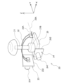
- 4A and 4B are diagrams illustrating the structure of a tilting operation member.
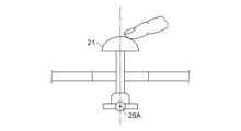
- 13A and 13B are diagrams illustrating a reference position of the tilt operation member.
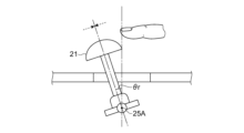
- 11 is a diagram for explaining an example of control of a target position according to a current position;
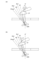
- FIG. 10A and 10B are diagrams for explaining an example of control of a target position according to an amount of tilt.
- FIG. 1 is a configuration block diagram showing the configuration of an information processing device 10 according to one embodiment of the present invention.
- the information processing device 10 is, for example, a home game console, a portable game console, a personal computer, etc., and as shown in the figure, is configured to include a control unit 11, a storage unit 12, and an interface unit 13.
- the information processing device 10 is also connected to a display device 14 and an operation device 15.
- the control unit 11 includes at least one processor such as a CPU, and executes programs stored in the storage unit 12 to perform various information processing. Specific examples of processing executed by the control unit 11 in this embodiment will be described later.
- the storage unit 12 includes at least one memory device such as a RAM, and stores the programs executed by the control unit 11 and the data processed by the programs.
- the interface unit 13 is an interface for data communication between the display device 14 and the operation device 15.
- the information processing device 10 is connected to each of the display device 14 and the operation device 15 via the interface unit 13, either wired or wirelessly.
- the interface unit 13 includes a multimedia interface for transmitting a video signal supplied by the information processing device 10 to the display device 14. It also includes a data communication interface for receiving a signal indicating the operation content performed by the user on the operation device 15.
- the interface unit 13 may be provided with a communication interface for transmitting and receiving data to and from other communication devices via a communication network such as the Internet.
- the display device 14 is a home television receiver or the like, and displays on its screen an image corresponding to the video signal supplied from the information processing device 10.
- the operation device 15 is, for example, a controller for a home game machine, and is equipped with multiple operation members for receiving operation input from the user.
- the operation device 15 is also connected to the information processing device 10 via a wired or wireless connection, and transmits and receives various types of data between the information processing device 10.
- the operating device 15 is equipped with a control unit 151 for controlling each part.
- the control unit 151 includes at least one processor, and periodically scans the contents of the operation input performed by the user on each operating member, and transmits an operation signal indicating the contents to the information processing device 10.
- the control unit 151 also controls the state of the tilt operation member 20 (described later) according to the contents of the instructions received from the information processing device 10.
- the operating device 15 has a tilt operation member 20 on its surface as a type of operating member.
- the tilt operation member 20 is an operating member that the user operates by tilting it with his or her hand or finger, and is configured to be tilted in any direction through 360 degrees.
- the operating device 15 is assumed to have a total of two tilt operation members 20, one on each side.
- the tilt operation member 20L when it is necessary to distinguish between the left and right tilt operation members 20, the tilt operation member 20 located on the left side of the operating device 15 will be referred to as the tilt operation member 20L, and the tilt operation member 20 on the right side will be referred to as the tilt operation member 20R.
- the user can independently operate the tilt operation member 20L with the thumb of his or her left hand and the tilt operation member 20R with the thumb of his or her right hand.
- the tilt operation member 20 includes a columnar body 21 to be tilted, a guide 22, a first actuator 23, a second actuator 24, and a base 25.
- the guide 22 and the base 25 are supported so as to be rotatable around axes 22A and 25A, respectively, at least within a predetermined angle range, with the direction of axis 22A being the X-axis and the direction of axis 25A being the Y-axis.
- the direction perpendicular to both the X-axis and the Y-axis is the Z-axis.
- the guide 22 rotates around axis 22A in the YZ plane.
- the base 25 rotates around axis 25A in the XZ plane.
- the guide 22 restricts the movement of the columnar body 21 in one direction (the X-axis direction). As described above, the guide 22 is supported so that it can rotate around the axis 22A within a predetermined angular range in the YZ plane. This angular range also includes the angular range in which the columnar body 21 is parallel to the Z-axis direction.
- the first actuator 23 and the second actuator 24 function as a drive unit that drives the columnar body 21, which is the main body of the tilt operation member 20, in response to a control signal received from the control unit 151.
- the first actuator 23 includes a motor 231 and a sensor 232.
- the motor 231 is, for example, a three-phase brushless DC motor (having 3n (n is a natural number) stators), and supplies current input from the control unit 151 to the stator coils of each phase to control the amount of rotation, speed, and direction of rotation of the rotor.
- the rotating shaft of the rotor of this motor 231 is connected to the shaft 22A of the guide 22, and the motor 231 rotates the guide 22 around the shaft 22A in the YZ plane.
- the sensor 232 is, for example, a rotary encoder, a potentiometer, or other angle sensor, and sequentially detects the rotation angle ⁇ c of the guide 22 around the axis 22A with a predetermined reference direction (for example, the direction of the guide 22 in a state in which the columnar body 21 can be oriented in the positive direction of the Z axis) set to 0 degrees, and outputs the detection result to the control unit 151.
- a predetermined reference direction for example, the direction of the guide 22 in a state in which the columnar body 21 can be oriented in the positive direction of the Z axis
- the second actuator 24 is composed of a motor 241 and a sensor 242.
- the motor 241 is, for example, a three-phase brushless DC motor, and supplies current input from the control unit 151 to the stator coils of each phase to control the amount of rotation, rotation speed, and rotation direction of the rotor.
- the rotation axis of the rotor of this motor 241 is connected to the axis 25A of the base 25, and the motor 241 rotates the base 25 around the axis 25A in the XZ plane.
- the sensor 242 is, for example, a rotary encoder, a potentiometer, or other angle sensor, and sequentially detects the rotation angle ⁇ c of the base 25 around the axis 25A with a predetermined reference direction (for example, the direction of the base 25 in a state in which the columnar body 21 can be oriented in the positive direction of the Z axis) set to 0 degrees, and outputs the detection result to the control unit 151.
- a predetermined reference direction for example, the direction of the base 25 in a state in which the columnar body 21 can be oriented in the positive direction of the Z axis
- the base 25 is supported so that it can rotate around its axis 25A at least within a predetermined angle range.
- the base 25 supports the base 21B of the columnar body 21 so that the columnar body 21 faces in the positive direction of the Z axis when the rotation angle around the axis 25A is 0 degrees.
- Sensor 232 and sensor 242 function as a position detection unit that detects the position of the tilt operation member 20.
- the control unit 151 determines the position of the tilt operation member 20 (i.e., in what direction and at what angle the columnar body 21 is tilted) based on the detection results of these sensors 232 and 242.
- the control unit 151 periodically transmits information indicating the position of this tilt operation member 20 to the information processing device 10 as operation information indicating the content of the operation performed by the user on the tilt operation member 20.
- the control unit 151 also includes a motor driver that controls the driving of the motor 231 based on the detection result of the sensor 232, and a motor driver that controls the driving of the motor 241 based on the detection result of the sensor 242.
- the control unit 151 drives the motor 231 and the motor 241 based on instructions from the information processing device 10, thereby tilting the columnar body 21 in any direction or angle, or controlling the change in the force required to tilt in a given direction.
- the tilt operation member 20 is disposed so that the tilt direction of the columnar body 21 caused by the motor 221 coincides with the left-right direction of the operating device 15, and the tilt direction of the columnar body 21 caused by the motor 231 coincides with the front-rear direction of the operating device 15. That is, the tilt angle ⁇ c of the axis 22A detected by the sensor 232 represents the tilt of the columnar body 21 along the left-right direction of the operating device 15, and the tilt angle ⁇ c of the axis 25A detected by the sensor 242 represents the tilt of the columnar body 21 along the front-rear direction of the operating device 15.
- the position of the tilt operation member 20 is identified by the pair of values of these two tilt angles ( ⁇ c, ⁇ c).
- the range of values that the pair of ( ⁇ c, ⁇ c) can take corresponds to a rectangular area in a two-dimensional space.
- the range of values that this pair of tilt angles can take is referred to as the movable range of the tilt operation member 20.
- the maximum angle at which the columnar body 21 can be physically tilted is limited by the housing of the operation device 15, and the physical movable range of the tilt operation member 20 may be a circular range, but here, the range of values that the detected pair of tilt angles can take is the movable range.
- FIG. 3 is a diagram showing the reference position of the tilt operation member 20, and shows a schematic view of the columnar body 21 viewed from the side.
- the position of the tilt operation member 20 can also be expressed by an azimuth angle ⁇ d and a tilt amount ⁇ r instead of a pair of ( ⁇ c, ⁇ c).
- the azimuth angle ⁇ d indicates the direction from the reference position O to the current position of the tilt operation member 20, and takes a value greater than or equal to 0° and less than 360° with a given direction as the reference direction.
- the tilt amount ⁇ r indicates the rotation angle of the columnar body 21 from the positive direction of the Z axis, with the state in which the columnar body 21 is at the reference position O being set to 0°, and the value increases as the columnar body 21 moves away from the reference position O.
- the azimuth angle ⁇ d indicates the direction of change in the position of the tilt operation member 20 as a result of the user's operation as seen from the reference position O
- the tilt amount ⁇ r indicates the amount of change in the position of the tilt operation member 20 from the reference position O as a result of the user's operation.
- the control unit 151 controls the columnar body 21 to move toward the target position, which is the reference position O.
- the control unit 151 controls the motors 231 and 241 to move the columnar body 21 toward the reference position O, and ends the drive control when the columnar body 21 reaches the reference position O.
- the tilt operation member 20 returns to the reference position O when the user releases his/her hand, regardless of the position, and comes to a stop at the reference position O.
- control unit 151 performs control to change the target position of the columnar body 21 according to the current position of the columnar body 21.
- the control unit 151 updates the target position so that the current position after the change always becomes the new target position.
- drive control is performed to maintain the position at that time. This makes it easier for the user to perform an operation to keep the pillar 21 stationary at any position.
- FIG. 4 is a diagram showing the control in this first example, and shows a schematic side view of the pillar 21.
- the posture of the pillar 21 is maintained at the timing when the user releases his/her finger.
- control unit 151 may update the target position each time the current position of the pillar 21 is scanned (i.e., each time the position of the pillar 21 is detected), so that the latest current position becomes the target position.
- control to move the pillar 21 toward the target position is not performed, but motors 231 and 241 are controlled so that the pillar 21 continues to remain stationary at the target position. This makes it possible to present the user with a sensation of frictional resistance when manipulating the pillar 21.
- the control unit 151 can change the magnitude of the force required for the user to perform an operation to change the position of the pillar 21 by, for example, controlling the magnitude of the torque on the motors 231 and 241.
- the control unit 151 executes the control of the target position according to this first example in response to an instruction from the information processing device 10, it also receives an instruction from the information processing device 10 regarding the strength of the force, and controls the motors 231 and 241 in response to the magnitude of the instructed force.
- This makes it possible to change the strength of the force required to operate the tilt operation member 20 in response to the content of the process executed by the information processing device 10 and instructions from the user. For example, when the control unit 151 executes control to maintain the target position with a relatively strong force, the user will need a stronger force to tilt the pillar 21, and the user can be presented with the sensation that the pillar 21 has become heavier.
- the control unit 151 may also update the target position less frequently than the frequency at which the position of the pillar 21 is periodically scanned. For example, the control unit 151 may update the most recent current position at that time to a new target position every time a given time elapses. Also, every time the current position of the pillar 21 changes by a predetermined amount from the current target position, the target position may be updated to the position at that time. In this way, when the position of the pillar 21 has only changed slightly, control is performed to return it to the target position, and when the position of the pillar 21 has changed relatively significantly by the user, control can be performed to update the target position to follow that change.
- the tilt amount ⁇ r of the columnar body 21 indicates the amount of change in the position of the columnar body 21 from the reference position O due to user operation.
- the control unit 151 changes the tilt amount ⁇ r of the target position (hereinafter referred to as the target tilt amount) depending on the magnitude of the tilt amount ⁇ r of the current position of the columnar body 21, and controls the azimuth angle ⁇ d of the target position to maintain the current azimuth angle.
- FIGS. 5(a) and 5(b) are diagrams showing an example of specific control content in this second example, and show a schematic side view of the pillar 21.
- the block arrows indicate the direction of movement of the pillar 21 by the user's operation
- the dashed arrows indicate the direction of control by the control unit 151 to move the pillar 21 to the target position.
- the control unit 151 divides the range in which the tilt amount ⁇ r of the columnar body 21 can take on into multiple angle ranges, and changes the target tilt amount depending on which of the multiple angle ranges the current tilt amount ⁇ r falls within. More specifically, the control unit 151 adopts a predetermined numerical value that belongs to the angle range in which the current tilt amount ⁇ r falls as the target tilt amount.
- the control unit 151 sets the target tilt amount to 0°, which is the minimum value of this angle range.
- the control unit 151 sets the target tilt amount to an angle ⁇ x1 included in this angle range.
- ⁇ x1 may be a value equivalent to the median value of the angle range from ⁇ 1 to ⁇ 2.
- the angle is calculated as follows:
- the target tilt amount is set to ⁇ x2.
- the angle may be calculated as follows:
- the control unit 151 changes the target tilt amount to ⁇ x1 at that time. Then, the resistance force that has been presented to the user until then to return the columnar body 21 to the reference position O disappears, and instead a force that tries to tilt the columnar body 21 further to the target tilt amount ⁇ x1 is applied. In other words, when the tilt amount ⁇ r reaches the threshold value ⁇ 1, the force applied to the columnar body 21 instantaneously changes to the opposite direction from before.
- Figure 5(b) shows the state of the columnar body 21 at this time. With this control, the user feels a tactile response similar to the clicking sensation felt when a mechanical switch is turned on when the tilt amount ⁇ r of the columnar body 21 exceeds the threshold value ⁇ 1.
- the target tilt amount differs depending on the angle range to which the current position of the pillar 21 belongs, so even if the user releases the pillar 21, the pillar 21 does not automatically return to the reference position O.
- the tilt amount ⁇ r is within the angle range 0° ⁇ r ⁇ 1
- the reference position O becomes the target position, so if the user performs an operation to return the pillar 21 to a position close to the reference position O, it can be automatically returned to the reference position O thereafter.
- the median value of that angle range is set as the target tilt amount.
- the target tilt amount may be set to an angle that deviates from the median value. For example, by setting the target tilt amount when the tilt amount ⁇ r of the columnar body 21 is within a certain angle range to an angle within that angle range that is close to the reference position O (i.e., a relatively small angle), it becomes possible for the user to immediately feel a force that opposes their operation when the tilt amount exceeds the target tilt amount.
- the range of values that the tilt amount ⁇ r can take, 0° ⁇ r ⁇ max, is divided into three angle ranges, and the target tilt amounts of 0°, ⁇ x1, and ⁇ x2 are set for each of these angle ranges.
- the control unit 151 may divide the range of values that the tilt amount ⁇ r can take into two or four or more angle ranges, and may set any target tilt amount for each angle range.
- the size of each angle range may be the same as each other, or may be different.
- control unit 151 may determine the size and number of these angle ranges, and the value of the target tilt amount in each angle range, in response to an instruction from the information processing device 10. In this way, the information processing device 10 can change the angle at which the clicking sensation is presented to the user in accordance with the processing content being executed by the information processing device 10.
- control unit 151 may change the magnitude of the force applied to move the pillar 21 toward the target position in response to an instruction from the information processing device 10. This makes it possible to change the sensation the user feels when crossing the boundary of the angle range.
- the information processing device 10 may specify different magnitudes of force applied to move the pillar 21 toward the target position for each of a plurality of angle ranges. This makes it possible to change the sensation the user feels for each angle.
- the target position of the tilt operation member 20 can be changed according to the position of the tilt operation member 20, and a different operating feel from the usual can be presented to the user operating the tilt operation member 20 with relatively simple processing.
- the embodiments of the present invention are not limited to those described above.
- the target position settings described above are merely examples, and the control unit 151 may change the target position depending on various conditions.
- the operating device 15 is not limited to a device that is held by the user, but may be a device that is used while placed on a table or the like.
- the tilt operating member 20 is also not limited to an operating member that is operated by the user with the thumb, but may have various shapes and structures, such as an operating member that is operated with other fingers or an operating member that is operated while being held by the user in the hand.
- the operation device 15 may be provided with an operation member that can be operated by sliding in any direction parallel to the surface of the housing within a predetermined range. In this case, too, by changing the target position based on the amount of change from the current position of the operation member or a reference position (for example, the center position of the movable range of the operation member), it is possible to maintain the operation member in any position or to present the user with a clicking sensation when the amount of change becomes equal to or exceeds a predetermined amount.
- a reference position for example, the center position of the movable range of the operation member
- control unit 151 performs control to change the target position depending on the position of the tilt operation member 20, but this is not limited to the above description. At least a part of the control performed by the control unit 151 in the above description may be performed by the information processing device 10 that is communicatively connected to the operation device 15.
- the operating device 15 periodically transmits operation information indicating the user's operation on each operating member of the operating device 15 to the information processing device 10.
- This operation information includes information indicating the position of the tilt operating member 20 as information indicating the user's operation on the tilt operating member 20.
- the information processing device 10 transmits instruction information to the operating device 15 instructing it to change the target position of the tilt operating member 20 according to the position of the tilt operating member 20 at that time, and to execute drive control to move the columnar body 21 toward the target position.
- the control unit 151 of the operating device 15 executes drive control of the tilt operating member 20 according to this instruction information. Even with this configuration, the target position of the tilt operating member 20 can be changed at any time by sending and receiving information between the operating device 15 and the information processing device 10 in a relatively short cycle.
- Control unit 10 Information processing device, 11 Control unit, 12 Memory unit, 13 Interface unit, 14 Display device, 15 Operation device, 151 Control unit, 20 Tilt operation member, 21 Pillar body, 22 Guide, 23 First actuator, 24 Second actuator, 25 Base.
Landscapes
- Engineering & Computer Science (AREA)
- General Engineering & Computer Science (AREA)
- Theoretical Computer Science (AREA)
- Human Computer Interaction (AREA)
- Physics & Mathematics (AREA)
- General Physics & Mathematics (AREA)
- Position Input By Displaying (AREA)
Abstract
Description
θx1=(θ1+θ2)/2
で算出される角度となる。
θx2=(θ2+θmax)/2
で算出される角度であってよい。
Claims (8)
- ユーザーにより傾倒乃至所定範囲内で移動操作可能な操作部材と、
前記ユーザーによって操作される前記操作部材の位置を検出する位置検出部と、
前記操作部材を駆動する駆動部と、
前記操作部材が所与の目標位置に近づくように前記駆動部を駆動させ、かつ、前記位置検出部が検出する前記操作部材の位置に応じて前記目標位置を変化させる制御部と、
を含む操作デバイス。 - 請求項1に記載の操作デバイスであって、
前記制御部は、前記ユーザーによって操作された前記操作部材の位置を前記目標位置として、前記操作部材の位置を維持するように前記操作部材を制御する
ことを特徴とする操作デバイス。 - 請求項1に記載の操作デバイスであって、
前記制御部は、前記操作部材の位置の所与の基準位置からの変化量に応じて、前記目標位置を変化させる
ことを特徴とする操作デバイス。 - 請求項3に記載の操作デバイスであって、
前記制御部は、前記操作部材の位置の前記基準位置からの変化量の取り得る範囲を複数の数値範囲に分割し、前記変化量が前記複数の数値範囲のうちのどの数値範囲に含まれるかに応じて、前記目標位置を変化させる
ことを特徴とする操作デバイス。 - 請求項4に記載の操作デバイスであって、
前記制御部は、前記変化量が前記複数の数値範囲のうちの一つの数値範囲に含まれる場合に、当該一つの数値範囲の中央値に対応する位置に、前記目標位置を変化させる
ことを特徴とする操作デバイス。 - ユーザーにより傾倒乃至所定範囲内で移動操作可能な操作部材と、
前記ユーザーによって操作される前記操作部材の位置を検出する位置検出部と、
前記操作部材を駆動する駆動部と、
を備える操作デバイスの制御方法であって、
前記操作部材が所与の目標位置に近づくように前記駆動部を駆動させ、
前記位置検出部が検出する前記操作部材の位置に応じて前記目標位置を変化させる、
操作デバイスの制御方法。 - ユーザーにより傾倒乃至所定範囲内で移動操作可能な操作部材と、
前記ユーザーによって操作される前記操作部材の位置を検出する位置検出部と、
前記操作部材を駆動する駆動部と、
を備える操作デバイスと接続される情報処理装置であって、
一つ以上のプロセッサを含み、
前記一つ以上のプロセッサは、
前記操作部材が所与の目標位置に近づくように前記駆動部を駆動させ、かつ、前記位置検出部が検出する前記操作部材の位置に応じて前記目標位置を変化させるように前記操作デバイスに対して指示する、
情報処理装置。 - ユーザーにより傾倒乃至所定範囲内で移動操作可能な操作部材と、
前記ユーザーによって操作される前記操作部材の位置を検出する位置検出部と、
前記操作部材を駆動する駆動部と、
を備える操作デバイスと接続されるコンピュータに、
前記操作部材が所与の目標位置に近づくように前記駆動部を駆動させ、かつ、前記位置検出部が検出する前記操作部材の位置に応じて前記目標位置を変化させるように前記操作デバイスに対して指示する、
処理を実行させるためのプログラム。
Priority Applications (2)
| Application Number | Priority Date | Filing Date | Title |
|---|---|---|---|
| CN202380093938.XA CN120752604A (zh) | 2023-02-22 | 2023-02-22 | 操作设备、用于控制操作设备的方法、信息处理装置和程序 |
| PCT/JP2023/006526 WO2024176402A1 (ja) | 2023-02-22 | 2023-02-22 | 操作デバイス、その制御方法、情報処理装置、及びプログラム |
Applications Claiming Priority (1)
| Application Number | Priority Date | Filing Date | Title |
|---|---|---|---|
| PCT/JP2023/006526 WO2024176402A1 (ja) | 2023-02-22 | 2023-02-22 | 操作デバイス、その制御方法、情報処理装置、及びプログラム |
Publications (1)
| Publication Number | Publication Date |
|---|---|
| WO2024176402A1 true WO2024176402A1 (ja) | 2024-08-29 |
Family
ID=92500330
Family Applications (1)
| Application Number | Title | Priority Date | Filing Date |
|---|---|---|---|
| PCT/JP2023/006526 Ceased WO2024176402A1 (ja) | 2023-02-22 | 2023-02-22 | 操作デバイス、その制御方法、情報処理装置、及びプログラム |
Country Status (2)
| Country | Link |
|---|---|
| CN (1) | CN120752604A (ja) |
| WO (1) | WO2024176402A1 (ja) |
Citations (2)
| Publication number | Priority date | Publication date | Assignee | Title |
|---|---|---|---|---|
| JP2009289036A (ja) * | 2008-05-29 | 2009-12-10 | Denso Corp | 車両用操作装置 |
| JP2015215730A (ja) * | 2014-05-09 | 2015-12-03 | パナソニックIpマネジメント株式会社 | 入出力操作装置 |
-
2023
- 2023-02-22 CN CN202380093938.XA patent/CN120752604A/zh active Pending
- 2023-02-22 WO PCT/JP2023/006526 patent/WO2024176402A1/ja not_active Ceased
Patent Citations (2)
| Publication number | Priority date | Publication date | Assignee | Title |
|---|---|---|---|---|
| JP2009289036A (ja) * | 2008-05-29 | 2009-12-10 | Denso Corp | 車両用操作装置 |
| JP2015215730A (ja) * | 2014-05-09 | 2015-12-03 | パナソニックIpマネジメント株式会社 | 入出力操作装置 |
Also Published As
| Publication number | Publication date |
|---|---|
| CN120752604A (zh) | 2025-10-03 |
Similar Documents
| Publication | Publication Date | Title |
|---|---|---|
| EP1497819B1 (en) | Haptic feedback using rotary harmonic moving mass | |
| JP4220355B2 (ja) | 力覚付与型入力装置 | |
| CN109478098B (zh) | 信息处理系统、操作装置和操作装置控制方法 | |
| US7420547B2 (en) | Method and apparatus for matching tactile sensation to the contents of a display | |
| US9663211B2 (en) | Boat maneuvering system | |
| EP3434245B1 (en) | Electric wheelchair operation apparatus and vehicle operation method therefor | |
| EP1406152A2 (en) | Inner-force providing input device having a power-operated actuator for generating a click feel | |
| JP5921904B2 (ja) | 無線操縦装置 | |
| JP2013256139A (ja) | 倒立振子型車両 | |
| JP2021084141A (ja) | 教示装置、制御方法および教示プログラム | |
| JP4117954B2 (ja) | 4軸のフォースフィードバックを有する力覚インタフェース装置 | |
| JP4030437B2 (ja) | 画像情報表示装置 | |
| CN120752604A (zh) | 操作设备、用于控制操作设备的方法、信息处理装置和程序 | |
| JPWO2020013039A1 (ja) | 情報処理装置及びコントローラ装置の制御方法 | |
| JP2011232793A (ja) | 入力装置 | |
| JP4180491B2 (ja) | 力覚付与型入力装置 | |
| WO2024105772A1 (ja) | 情報処理装置、操作デバイス、情報処理方法、及びプログラム | |
| US20250352890A1 (en) | Operating device, method for controlling operating device, information processing apparatus, and program | |
| EP4332733A1 (en) | Haptic module and controller having rotational weight distribution | |
| JP7561997B2 (ja) | コントローラ | |
| US20250325900A1 (en) | Information processing device, information processing method, and program | |
| JPH10202568A (ja) | 産業用ロボットおよびその教示方法 | |
| US20250319391A1 (en) | Controller device | |
| JP2017104194A (ja) | 動作支援装置、及び、動作支援装置の制御方法 | |
| US20250076916A1 (en) | Operation device |
Legal Events
| Date | Code | Title | Description |
|---|---|---|---|
| 121 | Ep: the epo has been informed by wipo that ep was designated in this application |
Ref document number: 23924054 Country of ref document: EP Kind code of ref document: A1 |
|
| WWE | Wipo information: entry into national phase |
Ref document number: 202380093938.X Country of ref document: CN |
|
| NENP | Non-entry into the national phase |
Ref country code: DE |
|
| WWP | Wipo information: published in national office |
Ref document number: 202380093938.X Country of ref document: CN |
|
| 122 | Ep: pct application non-entry in european phase |
Ref document number: 23924054 Country of ref document: EP Kind code of ref document: A1 |