WO2024172074A1 - 作業機 - Google Patents
作業機 Download PDFInfo
- Publication number
- WO2024172074A1 WO2024172074A1 PCT/JP2024/005026 JP2024005026W WO2024172074A1 WO 2024172074 A1 WO2024172074 A1 WO 2024172074A1 JP 2024005026 W JP2024005026 W JP 2024005026W WO 2024172074 A1 WO2024172074 A1 WO 2024172074A1
- Authority
- WO
- WIPO (PCT)
- Prior art keywords
- tool
- state
- clamp
- tip
- clamping
- Prior art date
- Legal status (The legal status is an assumption and is not a legal conclusion. Google has not performed a legal analysis and makes no representation as to the accuracy of the status listed.)
- Ceased
Links
Images










Classifications
-
- B—PERFORMING OPERATIONS; TRANSPORTING
- B25—HAND TOOLS; PORTABLE POWER-DRIVEN TOOLS; MANIPULATORS
- B25F—COMBINATION OR MULTI-PURPOSE TOOLS NOT OTHERWISE PROVIDED FOR; DETAILS OR COMPONENTS OF PORTABLE POWER-DRIVEN TOOLS NOT PARTICULARLY RELATED TO THE OPERATIONS PERFORMED AND NOT OTHERWISE PROVIDED FOR
- B25F5/00—Details or components of portable power-driven tools not particularly related to the operations performed and not otherwise provided for
Definitions
- the present invention relates to a work machine.
- the power tool shown in Patent Document 1 has a tool shaft that clamps the tool tip from below, a pair of clamp members that can swing around a pin to restrict the vertical movement of the tool shaft, and a clamp lever that allows the operator to change the state of the clamp members.
- the object of the present invention is to provide a work machine with improved workability.
- the working machine of one embodiment has a motor, an output shaft that is driven to rotate around an axis by the motor, an operating unit that can be operated by an operator, a clamping unit that can operate in response to the operation of the operating unit, and a tool holding unit that has a mounting seat that holds the tool tip by clamping the tool tip together with the clamping unit in the clamping direction, and is held by the output shaft.
- the tool holding unit can be in either a fixed state in which a biasing force in the clamping direction is applied to the tool tip to fix the tool tip to the tool holding unit, or a temporary holding state in which the biasing force in the clamping direction applied to the tool tip is weaker than in the fixed state.
- the tool holding portion in the fixed state is configured to be able to hold the tool tip at multiple rotational positions around the axis by the clamp portion.
- the temporary holding state includes a first state in which the rotation of the tool tip and the removal of the tool tip from the tool holding portion are restricted, and also includes at least one of a second state and a third state in which the tool tip held in the tool holding portion in the first state is biased.
- the tool tip In the second state, the tool tip can be rotated from one of the multiple rotation positions to another of the multiple rotation positions while the clamping portion prevents the tool tip from being removed from the tool holding portion.
- the clamping portion remains held by the output shaft, and the tool tip is permitted to move in a direction along the axis.
- the present invention can improve the workability of a work machine.
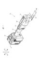
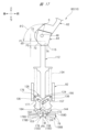
- FIG. 1 is a perspective view showing an electric power tool as a work machine according to a first embodiment.
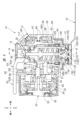
- FIG. 2 is a cross-sectional view (cross-sectional view taken along line AA in FIG. 1 ) showing the internal structure of the power tool;
- FIG. 4 is an enlarged cross-sectional view of the front portion of the power tool of FIG. 3 .
- FIG. 4 is an explanatory diagram showing a push piece.
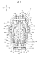
- 4 is a cross-sectional view (cross-sectional view taken along line BB in FIG. 3) showing the internal structure of the front portion of the power tool.
- FIG. 4 is a perspective view showing a state in which a first clamp member and a second clamp member are supported by a clamp holder;
- FIG. 1 is a perspective view showing an electric power tool as a work machine according to a first embodiment.
- FIG. 2 is a cross-sectional view (cross-sectional view taken along line AA in FIG. 1 ) showing the internal structure of the power tool
- FIG. 11 is a front view of the first clamp member and the second clamp member as viewed from the right side in the left-right direction.
- FIG. 4 is a perspective view showing a first clamp member.
- FIG. 4 is a perspective view showing a second clamp member.
- FIG. 11 is an explanatory diagram showing a state in which the clamp portion holds the tool bit.
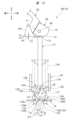
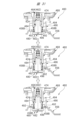
- 13 is an explanatory diagram showing a state in the middle of when the first clamp member and the second clamp member rotate toward the closing side in conjunction with rotation of the clamp lever;
- FIG. 11 is an explanatory diagram showing a state in which the first clamping member and the second clamping member temporarily hold the bit.
- FIG. 11 is an explanatory view showing a state in which the first clamping member and the second clamping member are in the release position (closed position) and the tool bit has been detached.
- FIG. 13 is an explanatory view showing a state in which the clamp lever has returned to a holding position and the O-ring is biasing the first clamp member and the second clamp member.
- FIG. 11 is an explanatory diagram showing a state in which a first clamping part and a second clamping part are inserted into a hole of the tool bit from above.
- FIG. 11 is an explanatory view showing a state in which a first clamping member and a second clamping member temporarily hold a tool bit.
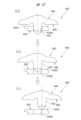
- FIG. 11 is an explanatory diagram showing a change in position of a clamp part relative to a hole of the tool bit when viewed in the clamping direction (up-down direction).
- FIG. FIG. 10 is an explanatory diagram showing a modified example of the first embodiment, illustrating a state in which the clamp member holds the tool bit.
- FIG. 10 is an explanatory diagram showing a modified example of the first embodiment, illustrating a state in which the clamp member temporarily holds the tool bit.
- FIG. 11 is an explanatory diagram illustrating a modified example of the first embodiment, showing a state in which the clamp member is in the release position (closed position) and the tool bit is detached.
- FIG. 11 is an explanatory diagram of a temporarily held state (first state) of a power tool as a work machine according to a second embodiment.
- 24 is an explanatory view showing an enlarged view of the first clamp member and the second clamp member of FIG. 23 .
- 24 is an explanatory diagram (a cross-sectional view taken along line AA in FIG. 23 ) showing the positional relationship between the tool holding portion and the tool bit in FIG. 23 .
- FIG. 24 is an explanatory diagram of the temporarily held state (second state) of the power tool of FIG. 23 .
- 26 is a cross-sectional view taken along line B-B of FIG. 26 and a cross-sectional view taken along line CC of FIG. 27, showing a state in the middle of rotation of the tip tool in the power tool of FIG.
- FIG. 24 is an explanatory diagram showing a state in which rotation of the tool tip of the power tool of FIG. 23 has been completed;
- FIG. FIG. 11 is an explanatory diagram showing a state in which a tool tip is fixed to a power tool as a working machine according to a third embodiment.
- FIG. 30 is an explanatory diagram showing a temporarily held state of the power tool of FIG. 29 .
- 30 is an explanatory diagram showing a change of the tool bit in the power tool of FIG. 29 from a fixed state to a temporarily held state (first state) and to a temporarily held state (second state).
- FIG. 31A and 31B are explanatory diagrams showing the change from a state in which the protrusion of the seating portion of the power tool in FIG.
- FIG. 29 is inserted into a through hole of the tool tip to a state in which the protrusion is removed from the through hole (cross-sectional views taken along lines D-D, E-E, and F-F in FIG. 31 ).
- 13 is an explanatory diagram showing a state in which a tool tip is fixed to a power tool as a working machine according to a modified example of the third embodiment.
- the direction indicated by the front and rear arrows is the front-rear direction
- the direction indicated by the left and right arrows is the left-right direction
- the direction indicated by the up and down arrows is the up-down direction.
- the front-rear direction, left-right direction and up-down direction are mutually perpendicular.
- the direction in which the clamp holder 126 and clamping parts 158, 178 (Fig. 4) described below clamp the tool bit 16 is defined as the clamping direction.
- the up-down direction is an example of the clamping direction. In the up-down direction, the upper side is the side on which the tool bit 16 is clamped, and the lower side is the side on which the tool bit 16 is released from the clamp.
- the up-down direction may be referred to as the clamping direction.
- the front-to-rear direction is an example of a cross direction that crosses the clamping direction.
- the side where the tool tip 16 is located is the front side, and the side where the battery pack 14 (described later) is located is the rear side.
- the left-to-right direction is an example of an axial direction that crosses both the clamping direction and the cross direction.
- FIG. 1 shows a power tool 10 as an example of a work machine.
- the power tool 10 includes an outer housing 12 and a battery pack 14, and is configured so that the tip tool 16 can be replaced with another tip tool.
- the power tool 10 is a cordless type multi-tool that operates on power from the battery pack 14. As an example, the power tool 10 vibrates the tip tool 16 in the direction indicated by the arrow RW.
- the outer housing 12 forms the outer shell of the power tool 10.
- the battery pack 14 is attached to and detached from the rear end of the outer housing 12.
- the power tool 10 can switch between a fixed state, a temporary holding state, and a released state with respect to the tool tip 16 by operating only the clamp lever 62, as will be described in detail later.
- the power tool 10 can switch from a fixed state to a released state and from a released state to a fixed state by operating only the clamp lever 62.
- the tip tool 16 is a member extending in the front-rear direction and has a front flat plate portion 17 and a rear mounting portion 18.
- the flat plate portion 17 is formed in a plate shape having a flat surface along the front-rear direction.
- a blade portion 17A is formed at the front end of the flat plate portion 17.
- the mounting portion 18 has a plate portion 19 and a protruding portion 21.
- the plate portion 19 is located diagonally above the flat plate portion 17.
- the protruding portion 21 protrudes upward from the upper surface of the plate portion 19.
- the outer periphery 21A of the protruding portion 21 has a shape in which multiple recesses 21B and multiple protrusions 21C are arranged alternately in the circumferential direction.
- An upper wall 22 is formed at the upper end of the protruding portion 21.
- the upper wall 22 is formed in a plate shape having a thickness in the vertical direction. In the center of the upper wall 22, one hole portion 24 that penetrates the upper wall 22 in the vertical direction and multiple through holes 26 are formed.
- the hole portion 24 has a circular insertion portion 25 and four cutout portions 27 that extend radially outward from the insertion portion 25.
- a clamp member 142 (FIG. 4), which will be described later, is inserted into the insertion portion 25.
- the multiple through holes 26 are arranged at intervals in the circumferential direction on the outer periphery of the upper wall 22.
- Figure 3 shows the internal structure of the power tool 10.
- the outer housing 12 is, as an example, a resin molded body.
- the outer housing 12 is formed in a cylindrical shape having a central axis along the front-rear direction.
- a lower opening 13 is formed at the front lower end of the outer housing 12.
- An upper opening 15 is formed at the front upper end of the outer housing 12.
- a clamp lever 62 (described later) and a trigger 61 are provided on the top of the outer housing 12.
- the trigger 61 is connected to a switch 41.
- the switch 41 is switched on and off, and the motor 52 is switched between driving and stopping.
- the inner housing 32, the control board 40, the switch 41, etc. are housed inside the outer housing 12.
- the inner housing 32 is formed in a cylindrical shape with a bottom and an open front.
- the inner housing 32 is positioned at a distance from the inner surface of the outer housing 12.
- the inner housing 32 has, as an example, a motor housing 34, an intermediate housing 35, and a holder 36.
- the rear end of the intermediate housing 35 is attached to the motor housing 34.
- a motor 52 is housed inside the motor housing 34.
- the holder 36 is a metal member, and is made of aluminum, for example.
- the holder 36 has an attachment portion 37, a tubular portion 38, and a support wall 39.
- the intermediate housing 35 is attached to the attachment portion 37.
- the tubular portion 38 is located forward of the attachment portion 37.
- the tubular portion 38 is formed in a cylindrical shape with a central axis along the up-down direction.
- the support wall 39 is provided at the upper end of the tubular portion 38.
- the support wall 39 supports both ends of the axial direction of the cylindrical pin 46.
- the axial direction of the pin 46 is along the left-right direction.
- a ball bearing 42, a needle bearing 43, an oil seal 44, and an output shaft portion 90, which will be described later, are provided inside the tubular portion 38.
- the ball bearing 42 is located forward and above the swing arm 88, which will be described later.
- the ball bearing 42 and the needle bearing 43 have a central axis along the vertical direction.
- the ball bearing 42 supports the guide portion 98, which will be described later, so that it can rotate freely around the central axis.
- the needle bearing 43 is located forward and below the swing arm 88, and supports the storage portion 94, which will be described later, so that it can rotate freely.
- the oil seal 44 is located below the needle bearing 43. The oil seal 44 seals the gap between the lower part of the holder 36 and the lower part of the storage portion 94.
- the outer housing 12 supports the tube portion 38 via a rubber member 48.
- the inner housing 32 is supported by the outer housing 12 via the rubber member 48, and is therefore in a floating state relative to the outer housing 12.
- the rubber member 48 is formed in a C-shape when viewed from the top and bottom. When the motor 52, which will be described later, is in operation, the rubber member 48 suppresses the transmission of vibrations from the holder 36 to the outer housing 12.
- the motor 52 is located in the center of the outer housing 12 in the front-rear direction.
- the motor 52 is a brushless motor.
- the motor 52 has a rotating shaft 53.
- the rotating shaft 53 extends along the front-rear direction.
- the control board 40 is equipped with a controller that controls the drive of the motor 52, switching elements, etc.
- the clamp lever 62 is an example of an operating part that can be operated by an operator.
- the clamp lever 62 has a lever body 63 and a push piece 64.
- the lever body 63 has a pair of base ends 63A and a gripping part 63B extending rearward from the pair of base ends 63A.
- the pair of base ends 63A face each other with a gap in the left-right direction.
- the push piece 64 is fixed between the pair of base ends 63A.
- the pin 46 penetrates the push piece 64 and the pair of base ends 63A in the left-right direction.
- the clamp lever 62 is rotatably connected to the support wall 39 with the pin 46 as the central axis.
- the grip portion 63B is exposed to the outside of the outer housing 12 through the upper opening 15. This allows an operator to operate the clamp lever 62.
- the grip portion 63B is rotated around the pin 46 by being gripped by the operator.
- the operation of rotating the clamp lever 62 by rotating the grip portion 63B forward is referred to as the "release operation”
- the operation of rotating the grip portion 63B backward is referred to as the "attachment operation.”
- the rotation direction of the clamp lever 62 the rotation direction when the grip portion 63B faces forward is referred to as the +R direction
- the rotation direction when the grip portion 63B faces backward is referred to as the -R direction.
- the clamp lever 62 can hold the clamp shaft 112 (described later) at a third position P3 (FIG. 14) between the first position P1 (FIG. 12) and the second position P2 (FIG. 15). More specifically, the clamp shaft 112 (described later) is configured to move between the first position P1 and the second position P2 in response to the operation of the clamp lever 62.
- the clamp lever 62 can hold the clamp shaft 112 at a position (temporary lever holding position) that positions the clamp shaft 112 at the third position P3 between the first position P1 and the second position P2.
- the clamp lever 62 can hold a position between a fixed position when the clamp member 142 is in the clamped state and a released position when the clamp member 142 is in the released state.
- Figure 5 shows the position of the push piece 64 when the tool tip 16 ( Figure 1) is fixed to the power tool 10.
- the position of the push piece 64 changes as the clamp lever 62 rotates.
- the push piece 64 is a metal block-shaped member.
- the push piece 64 is positioned so that it can come into contact with or separate from the upper end surface 115 of the clamp shaft 112, which will be described later.
- the contact position of the push piece 64 with the upper end surface 115 changes as the clamp lever 62 rotates.
- the push piece 64 is an example of a moving part that can move the clamp shaft 112 to a third position P3 (FIG. 14) described below.
- the push piece 64 (clamp lever 62) is rotated to switch the tool bit 16 between a fixed (held) state, a temporary held state, and a released state.
- the push piece 64 has an outer periphery 65 when viewed from the left-right direction, which is the axial direction of the pin 46.
- the outer periphery 65 has a non-contact portion 66 that does not contact the clamp shaft 112, and a contact portion 71 that can contact the clamp shaft 112.
- the non-contact portion 66 has a plane 67 along the front-rear direction and a plane 68 along the up-down direction.
- the contact portion 71 has a first plane 72, a curved surface 73, and a second plane 74. Note that the +R direction already mentioned corresponds to the rotation direction of the push piece 64 when the tip tool 16 is removed. The -R direction corresponds to the rotation direction of the push piece 64 when the tip tool 16 is attached.
- the plane 68, the first plane 72, the curved surface 73, the second plane 74, and the plane 67 are located in this order in the -R direction.
- the angle between the plane 68 and the first plane 72 is nearly a right angle.
- the angle between the second plane 74 and the plane 67 is an obtuse angle.
- the shortest distance L1 from the center C1 of the pin 46 to the first plane 72 is shorter than the shortest distance L2 from the center C1 to the second plane 74.
- the distance L3 from the center C1 to the curved surface 73 increases continuously from the start point A1 to the end point A2 of the curved surface 73 in the -R direction.
- the second plane 74 extends from the end point A2 toward a position above and to the rear.
- a contact portion 71 is formed so as to move the clamp shaft 112 to the third position P3 ( Figure 14) when the clamp shaft 112 is located in the second position P2 ( Figure 15) and the operating force on the clamp lever 62 is released.
- the drive mechanism 80 includes a spindle 82, a ball bearing 84, an eccentric shaft portion 86, a swing arm 88, and an output shaft portion 90.
- the output shaft portion 90 includes a clamp shaft 112 and a clamp holder 126, and is configured to allow the clamp shaft 112 to swing around its own axis.
- a spindle 82 is attached to the front of the rotating shaft 53 of the motor 52.
- the spindle 82 extends in the front-to-rear direction and rotates together with the rotating shaft 53.
- a ball bearing 84 is supported by the intermediate housing 35.
- the ball bearing 84 rotatably supports the center of the spindle 82 in the front-to-rear direction.
- An eccentric shaft portion 86 is provided at the front end of the spindle 82.
- the central axis of the eccentric shaft portion 86 is parallel to the central axis of the spindle 82 and is offset from the central axis of the spindle 82.
- the swing arm 88 When viewed from the top-bottom direction, the swing arm 88 has an annular mounting portion 88A and a U-shaped arm portion 88B extending rearward from the mounting portion 88A.
- the mounting portion 88A is fixed to the outer peripheral surface of the unit case 92, which will be described later.
- the arm portion 88B sandwiches the outer peripheral portion of the eccentric shaft portion 86.
- the swing arm 88 links the rotational movement of the eccentric shaft portion 86 with the movement of the unit case 92.
- the rotation of the eccentric shaft portion 86 causes the arm portion 88B to swing left and right. This causes the output shaft portion 90 to vibrate in the rotational direction around its own axis.
- Figure 6 shows the internal structure of the front part of the power tool 10. Note that hatching has been omitted to clearly show the shape of each part.
- the output shaft portion 90 constitutes the portion of the power tool 10 that holds the tool tip 16 and vibrates.
- the output shaft portion 90 has a unit case 92, a clamp shaft 112, a clamp holder 126, a support pin 132, a clamp spring 134, an O-ring 136, and a clamp member 142.
- the unit case 92 has a storage section 94, an upper wall section 96, a guide section 98, a first enlarged diameter section 102 and a second enlarged diameter section 104.
- the unit case 92 includes (or supports) a tool holding section 100.
- the accommodation portion 94 is a cylindrical portion with its axial direction extending in the vertical direction.
- the accommodation portion 94 has an outer peripheral surface 94A and an inner peripheral surface 94B that are circular when viewed from the vertical direction.
- the swing arm 88 is fixed to the upper portion of the accommodation portion 94.
- the vertical center of the accommodation portion 94 is in contact with the inner ring portion of the needle bearing 43.
- the lower portion of the accommodation portion 94 is in contact with the oil seal 44.
- a clamp holder 126 (described later) is accommodated.
- the upper wall portion 96 is a portion formed in a disk shape, and covers the upper end portion of the storage portion 94.
- the guide portion 98 extends upward from the upper wall portion 96.
- the guide portion 98 is a cylindrical portion having a central axis along the vertical direction.
- the guide portion 98 is supported by the ball bearing 42 so as to be rotatable around the central axis along the vertical direction.
- a through hole 99 is formed in the upper wall portion 96 and the guide portion 98. The through hole 99 penetrates the upper wall portion 96 and the guide portion 98 in the vertical direction.
- the first enlarged diameter portion 102 extends downward from the lower end of the storage portion 94.
- the first enlarged diameter portion 102 is a cylindrical portion having a central axis along the up-down direction.
- the inner diameter of the first enlarged diameter portion 102 is larger than the inner diameter of the storage portion 94.
- the first enlarged diameter portion 102 is a portion that is enlarged in diameter relative to the storage portion 94.
- a step surface 103 is formed between the storage portion 94 and the first enlarged diameter portion 102.
- the second enlarged diameter portion 104 extends downward from the lower end of the first enlarged diameter portion 102.
- the second enlarged diameter portion 104 is a cylindrical portion having a central axis along the up-down direction.
- the inner diameter of the second enlarged diameter portion 104 is larger than the inner diameter of the first enlarged diameter portion 102.
- the second enlarged diameter portion 104 is an enlarged portion relative to the first enlarged diameter portion 102.
- a step surface 105 is formed between the first enlarged diameter portion 102 and the second enlarged diameter portion 104.
- the inner circumferential surface 104A of the second enlarged diameter portion 104 is provided with a mounting seat 107 (clamp base).
- the mounting seat 107 engages with the tool tip 16 in a rotational direction about the vertical direction (the extension direction of the central axis C2 described later).
- a plurality of recesses 107A and protrusions 107B are alternately arranged along the circumferential direction of the inner circumferential surface 104A.
- a slope 108 is formed at the lower end of the inner circumferential surface 104A.
- the mounting seat 107 contacts the tool tip 16 (FIG. 2) to transmit power in the rotational direction centered on the clamp shaft 112 (FIG. 3) to the tool tip 16.
- the second enlarged diameter portion 104 is provided with a through hole 106 that penetrates in the radial direction through the center of the second enlarged diameter portion 104.
- the mounting seat 107 is a part of the tool holding portion 100. The mounting seat 107 holds the tool tip 16 by clamping the tool tip 16 (FIG. 4) in the clamping direction together with the clamping parts 158 and 178 (FIG. 4) described below.
- the clamp shaft 112 moves between a first position P1 and a second position P2 (FIG. 15) in response to the operation of the clamp lever 62.
- the clamp shaft 112 is an example of an output shaft that extends vertically from a clamp holder 126, which will be described later.
- the clamp shaft 112 is a metal member, and has a first shaft portion 114, a second shaft portion 116, a flange portion 118, a support portion 122, and a guide pin 124.
- the first shaft portion 114, the second shaft portion 116, the flange portion 118, and the support portion 122 are integrally formed.
- the first shaft portion 114 is formed in a cylindrical shape having a central axis C2 along the up-down direction.
- the first shaft portion 114 passes through the through hole 99 from the inside of the storage portion 94 and protrudes above the upper end of the guide portion 98.
- the outer peripheral surface of the first shaft portion 114 is in contact with the inner peripheral surface of the through hole 99.
- the first shaft portion 114 is guided in the up-down direction by the guide portion 98.
- the surface located at the upper end of the first shaft portion 114 is referred to as the upper end surface 115.
- the upper end surface 115 is a flat surface that is aligned in both the front-rear direction and the left-right direction.
- the upper end surface 115 is located in a position that can come into contact with the outer peripheral portion 65.
- the second shaft portion 116 extends downward from the lower end of the first shaft portion 114.
- the second shaft portion 116 is formed in a cylindrical shape.
- the outer diameter of the second shaft portion 116 is larger than the outer diameter of the first shaft portion 114.
- the flange portion 118 is a disk-shaped portion that protrudes radially outward from the boundary between the first shaft portion 114 and the second shaft portion 116.
- the flange portion 118 is located inside the storage portion 94 and below the upper wall portion 96.
- the support portion 122 extends downward from the lower end of the second shaft portion 116.
- the support portion 122 has opposing walls 122A and 122B.
- the opposing walls 122A and 122B face each other with a gap in between in the left-right direction.
- the guide pin 124 is an example of a pin member.
- the guide pin 124 is formed in a cylindrical shape with a central axis along the left-right direction.
- the guide pin 124 connects the opposing walls 122A and 122B in the left-right direction.
- the support portion 122 supports both axial ends of the guide pin 124.
- the guide pin 124 is attached to the clamp shaft 112.
- the guide pin 124 is inserted into link holes 157, 177 (Fig. 9) of the movable portions 156, 176 (Fig. 9) described below.
- the clamp holder 126 has a base 127, multiple vertical wall portions 128, a horizontal wall portion 129, and a support pin 132.
- the clamp holder 126 is fixed to the lower portion of the unit case 92 (FIG. 6). Inside the clamp holder 126, a space is formed that is large enough to allow the lower portion of the support portion 122 (FIG. 6) and the clamp member 142 to operate.
- the base 127 is formed in a circular shape when viewed from the top-bottom direction.
- the base 127 is located inside the second enlarged diameter portion 104 ( Figure 6).
- a lower surface 127A is formed at the lower end of the base 127 along both the front-rear and left-right directions.
- the opening 127B penetrates the base 127 in the top-bottom direction. When viewed from below, the opening 127B is formed in a rectangular shape having long sides along the front-rear direction and short sides along the left-right direction.
- the opening 127B has a size that allows the clamp member 142 to move.
- the vertical wall portions 128 stand upright upward from the base portion 127.
- the vertical wall portions 128 are spaced apart in the circumferential and radial directions.
- the vertical wall portions 128 are located inside the first enlarged diameter portion 102 ( Figure 6).
- the vertical wall portions 128 have recesses 131 that are recessed in the radial direction.
- the horizontal wall portion 129 connects the upper ends of the vertical wall portions 128.
- the support pin 132 is an example of a support shaft extending in the left-right direction.
- the support pin 132 is formed in a cylindrical shape.
- the support pin 132 passes through the center position of the base 127 and penetrates the base 127 in the radial direction.
- the support pin 132 is fixed to the base 127 and does not rotate. Both left-right ends of the support pin 132 are fixed to and supported by the second enlarged diameter portion 104 ( Figure 6).
- the clamp spring 134 is provided between the second shaft portion 116 of the clamp shaft 112 and the inner peripheral surface 94B of the unit case 92.
- the clamp spring 134 is expandable and contractable in the vertical direction.
- the upper end of the clamp spring 134 engages with the lower surface of the flange portion 118.
- the lower end of the clamp spring 134 contacts the side wall portion 129 (FIG. 8) of the clamp holder 126.
- the clamp spring 134 applies a pressing force to the clamp shaft 112 by pressing the flange portion 118 upward. This causes an upward pressing force to act on the guide pin 124. Note that the first shaft portion 114 is held in a state where it protrudes upward from the guide portion 98 due to the pressing force of the clamp spring 134.
- O-ring 136 is an example of a biasing portion and an example of an annular elastic body.
- O-ring 136 is a rubber member having a circular ring shape.
- O-ring 136 spans multiple vertical wall portions 128 and is wrapped around recessed portion 131.
- the portions located at the front and rear are called pressing portions 137.
- Pressing portion 137 is a portion that is not in contact with multiple vertical wall portions 128. Pressing portion 137 is elastically deformable at least in the front-to-rear direction.
- the movable parts 156, 176 ( Figure 9) of the clamp member 142 which will be described later, are located inside the O-ring 136. Furthermore, when the clamp member 142 is located in the release position, a part of the O-ring 136 (the outer peripheral part of the pressing part 137) is in contact with the inner peripheral surface 94B ( Figure 6). This is because the O-ring 136 is deformed into an elliptical shape by the movable parts 156, 176. Here, when the movable parts 156, 176 come into contact with the pressing part 137, the elastically deformed O-ring 136 urges the movable parts 156, 176 inward.
- the restoring force of the deformed O-ring 136 urges the movable parts 156, 176 inward, and the clamp parts 158, 178 are urged outward. More specifically, the pressing portion 137 is deformed in the front-rear direction (radial direction) by the movable portions 156, 176 moving outward (front-rear direction), and as a result, the restoring force of the O-ring 136, which is deformed into an elliptical shape, biases the movable portions 156, 176 radially inward (front-rear direction). As a result, the pressing portion 137 exerts a pressing force (restoring force) toward the movable portions 156, 176 radially inward. In this way, the O-ring 136 is provided on the clamp holder 126 so that when it comes into contact with the clamp member 142, it biases the clamp member 142 radially inward.
- the O-ring 136 surrounds the movable parts 156, 176 of both the first clamp member 144 and the second clamp member 164.
- the O-ring 136 is an example of a biasing member that biases the movable parts 156, 176 so that the clamp parts 158, 178 move toward the open position described below.
- the O-ring 136 biases the clamp parts 158, 178 located in the closed position described below toward the open position (to move to the open position).
- the O-ring 136 biases both the movable parts 156 and 176 toward the inside (center) in the front-rear direction.
- the O-ring 136 is provided to continuously bias the clamp parts 158, 178 located in the open position.
- the clamp member 142 is rotatable around the support pin 132.
- the clamp member 142 has a first clamp member 144 and a second clamp member 164 that are rotatable in opposite directions around the support pin 132.
- a portion of the first clamp member 144 is located to the right of a portion of the second clamp member 164.
- the clamp member 142 has a pair of clamp portions 158, 178. Movable portions 156, 176 that are biased by an O-ring 136 are provided on the other side (upper side) of the clamp member 142 in the clamping direction relative to the support pin 132.
- the movable part 156 and the clamp part 158 are arranged so that as one moves to one side (front) in the fore-and-aft direction, the other moves to the other side (rear) in the fore-and-aft direction.
- the movable part 176 and the clamp part 178 are arranged so that as one moves to the front, the other moves to the rear.
- the first clamp member 144 and the second clamp member 164 will be described in detail below.
- the clamp members are part of the tool holding part 100.
- the first clamp member 144 has an insertion portion 146, a protruding portion 148, a leg portion 152, a protruding portion 154, a movable portion 156, and a clamp portion 158.
- the through-through portion 146 constitutes the vertical center of the first clamp member 144.
- the through-through portion 146 has a circular through-hole 146A that penetrates in the left-right direction.
- the support pin 132 ( Figure 9) is inserted into the through-hole 146A.
- a contact surface 147 is formed on the left end of the through-through portion 146 and the left end of the movable portion 156.
- the contact surface 147 is formed in a flat shape that extends along both the vertical and front-to-rear directions.
- Protruding portion 148 protrudes to the left side from contact surface 147.
- An upper surface 148A is formed at the upper end of protruding portion 148.
- a curved surface 149 is formed at the front end of insertion portion 146 and the front end of protruding portion 148. Curved surface 149 is formed in an arc shape when viewed from the left-right direction.
- the leg 152 extends downward from the lower end of the insertion portion 146 and the lower end of the overhang portion 148.
- Opposing surfaces 153 are formed at the rear end of the leg 152 and the rear end of the clamp portion 158.
- the opposing surfaces 153 are formed in flat shapes that extend in both the up-down and left-right directions.
- the protrusion 154 protrudes to the left side from the front end of the contact surface 147.
- the protrusion 154 is formed in a rectangular column shape extending in the left-right direction.
- the protrusion 154 restricts the rotation of the second clamp member 164 ( Figure 11) to the front side when the movable part 176 comes into contact with it.
- the movable part 156 is provided on the other side (upper side) of the clamping direction relative to the support pin 132 of the first clamp member 144.
- the movable part 156 is biased by an O-ring 136 ( Figure 9).
- the movable part 156 extends forward and upward (diagonally upward) from the upper end of the insertion part 146.
- a link hole 157 is formed (provided) in the movable part 156, penetrating it in the left-right direction.
- the link hole 157 is an example of a link part extending in a direction intersecting the clamping direction.
- the link hole 157 has a long hole portion 157A located on the front side (upper side) and a widened portion 157B located on the rear side (lower side).
- the long hole portion 157A and the widened portion 157B are integrally formed and are continuous as a hole.
- the long hole portion 157A is a portion in which the width of the hole is approximately the same at each position diagonally upward.
- the width of the long hole portion 157A is only slightly larger than the diameter of the guide pin 124. Therefore, when the guide pin 124 is located in the long hole portion 157A, the movement of the movable part 156 is restricted by the guide pin 124.
- the widened portion 157B is a trapezoidal portion in which the width of the hole gradually widens diagonally downward. Note that the lower surface of the widened portion 157B is inclined at the same angle as the lower surface of the long hole portion 157A, while the upper surface is at a different angle from the upper surface of the long hole portion 157A. Specifically, the upper surface of the widened portion 157B is configured to have a more blunt (obtuse) inclination angle with respect to the vertical direction than the upper surface of the long hole portion 157A. By configuring in this manner, the width of the widened portion 157B is made larger than that of the long hole portion 157A.
- the width of the widened portion 157B is made larger than the diameter of the guide pin 124.
- a gap is generated between the widened portion 157B and the guide pin 124.
- the restriction of the movement of the movable portion 156 by the guide pin 124 is weakened compared to when the guide pin 124 is located in the long hole portion 157A.
- the gap between the widened portion 157B and the guide pin 124 is configured to be larger than one-fifth of the radius of the guide pin 124.
- the clamping portion 158 extends downward and forward from the lower end of the leg 152.
- the clamping portion 158 is provided on one side (lower side) of the first clamping member 144 in the clamping direction relative to the support pin 132.
- the clamping portion 158 is formed in a substantially semicircular shape when viewed from below.
- the clamping portion 158 protrudes forward from the lower end of the leg 152, and the insertion portion 146 protrudes forward from the upper end of the leg 152, forming a U-shaped groove portion 161.
- the clamping portion 158 has a bottom surface 158A, a tapered surface 158B, a side surface 158C, a holding surface 158D, and an opposing surface 153.
- the bottom surface 158A is formed as a flat surface along both the front-rear and left-right directions.
- the tapered surface 158B is an example of a tapered portion, and extends diagonally upward from the outer periphery of the bottom surface 158A. In other words, the tapered surface 158B is along a diagonal direction that intersects with the clamping direction.
- the side surface 158C extends upward from the upper end of the tapered surface 158B.
- the holding surface 158D extends from the upper end of the side surface 158C toward the outer circumferential surface of the leg portion 152.
- the holding surface 158D extends diagonally downward so that the front end is located lower than the rear end.
- the holding surface 158D is formed in a flat shape. Therefore, when the holding surface 158D is arranged along the front-rear and left-right directions (horizontal direction), the holding surface 158D can hold the tip tool 16 (Figure 1) from below. Note that the thickness may vary depending on the type of tip tool, and the holding surface 158D is not necessarily horizontal when holding the tip tool.
- the second clamp member 164 is provided with an insertion portion 166, a protruding portion 168, a leg portion 172, a protrusion portion 174, a movable portion 176, and a clamp portion 178.
- the second clamp member 164 has the same shape and size as the first clamp member 144 (FIG. 10).
- the second clamp member 164 is the same as the first clamp member 144 rotated 180° around an axis along the vertical direction.
- the first clamp member 144 and the second clamp member 164 are distinguished by using different reference numerals because their positions relative to the support pin 132 (FIG. 9) are different in the front-to-back direction.
- the through-through portion 166 constitutes the vertical center of the second clamp member 164.
- the through-through portion 166 is formed with a circular through-hole 166A penetrating in the left-right direction.
- the support pin 132 (Fig. 9) is inserted into the through-hole 166A.
- a contact surface 167 is formed on the right end of the through-through portion 166 and the right end of the movable portion 176.
- the contact surface 167 is formed in a flat shape that extends along both the up-down direction and the front-rear direction. The contact surface 167 comes into contact with the contact surface 147 (Fig. 10) in the left-right direction.
- Protruding portion 168 protrudes to the right from contact surface 167.
- An upper surface 168A is formed at the upper end of protruding portion 168.
- a curved surface 169 is formed at the front end of insertion portion 166 and the front end of protruding portion 168. Curved surface 169 is formed in an arc shape when viewed from the left-right direction.
- the leg 172 extends downward from the lower end of the insertion portion 166 and the lower end of the overhang portion 168.
- An opposing surface 173 is formed at the rear end of the leg 172 and the rear end of the clamp portion 178.
- the opposing surface 173 is formed as a flat surface along both the up-down direction and the left-right direction.
- the opposing surface 173 is configured to be able to face or come into contact with the opposing surface 153 ( Figure 10) in the front-rear direction.
- the protrusion 174 protrudes to the right from the rear end of the contact surface 167.
- the protrusion 174 is formed in a rectangular column shape extending in the left-right direction.
- the protrusion 174 restricts the rotation of the first clamp member 144 ( Figure 10) to the rear when the movable part 156 comes into contact with it.
- the movable part 176 is provided on the other side (upper side) of the clamping direction relative to the support pin 132 of the second clamp member 164.
- the movable part 176 is biased by an O-ring 136 ( Figure 9).
- the movable part 176 extends rearward and upward (diagonally upward) from the upper end of the insertion part 166.
- a link hole 177 is formed (provided) in the movable part 176, penetrating it in the left-right direction.
- the link hole 177 is an example of a link part extending in a direction intersecting the clamping direction.
- the long hole portion 177A located on the rear side and the widened portion 177B located on the front side are integrally formed.
- the long hole portion 177A is a portion where the width of the hole is approximately the same at each position diagonally upward.
- the widened portion 177B is a trapezoidal portion where the width of the hole gradually widens diagonally downward.
- the relationship between the diameter of the guide pin 124 and the widths of the long hole portion 177A and the widened portion 177B is the same as in the case of the first clamp member 144. In other words, when the guide pin 124 is located in the widened portion 177B, the restriction of the movement of the movable portion 176 by the guide pin 124 is weaker than when the guide pin 124 is located in the long hole portion 177A.
- the clamping portion 178 extends downward and rearward from the lower end of the leg 172.
- the clamping portion 178 is provided on one side (lower side) of the second clamping member 164 in the clamping direction relative to the support pin 132.
- the clamping portion 178 is formed in a substantially semicircular shape when viewed from below.
- the clamping portion 178 protrudes rearward from the lower end of the leg 172, and the insertion portion 166 protrudes rearward from the upper end of the leg 172, forming a U-shaped groove portion 181.
- the clamping portion 178 has a bottom surface 178A, a tapered surface 178B, a side surface 178C, a holding surface 178D, and an opposing surface 173.
- the bottom surface 178A is formed as a flat surface along both the front-rear and left-right directions.
- the tapered surface 178B is an example of a tapered portion, and extends diagonally upward from the outer periphery of the bottom surface 178A. In other words, the tapered surface 178B is along a diagonal direction that intersects with the clamping direction.
- Side surface 178C extends upward from the upper end of tapered surface 178B.
- Holding surface 178D extends from the upper end of side surface 178C toward the outer circumferential surface of leg portion 172. Holding surface 178D extends diagonally downward so that its rear end is located lower than its front end. Note that holding surface 178D is formed in a flat shape. Therefore, when holding surface 178D is positioned horizontally, holding surface 178D can hold tip tool 16 from below. Note that holding surface 178D is not necessarily horizontal, similar to holding surface 158D.
- the clamping parts 158, 178 are provided on the clamp holder 126 (tool holding part 100) so that they can rotate (open and close) on different sides in the front-rear direction in response to the up-down movement of the clamping shaft 112.
- the clamping parts 158, 178 are rotatably supported on the support pin 132, and are switched between an open position and a closed position in the front-rear direction by the rotation. The open position and the closed position will be described later.
- the clamping parts 158, 178 are provided on the clamp holder 126 so that they can move in the front-rear direction in response to the rotation of the first clamping member 144 and the second clamping member 164.
- the state in which the clamp parts 158, 178 urge the tool tip 16 toward the clamp holder 126 and the unit case 92 and the tool tip 16 is fixed is referred to as the clamped state (fixed state) of the clamp parts 158, 178 (clamp members 142).
- the vertical position of the clamp shaft 112 (upper end surface 115) when the tool tip 16 is fixed is referred to as the first position P1.
- the vertical position of the clamp shaft 112 is represented by the position of the upper end surface 115.
- the clamp shaft 112 is a member that moves in the vertical direction, but if the position of the clamp shaft 112 is the same when the tool tip 16 is held and when it is not held, there is a risk that the tool tip 16 will not be properly clamped, so the first position P1 does not have to be the uppermost position of the clamp shaft 112.
- the first position P1 may be a position slightly below the uppermost position of the clamp shaft 112. In this case, the upward movement of the clamp shaft 112 located at the uppermost position may be restricted by the push piece 64, or may be restricted by the inner portion of the unit case 92.
- the clamp portions 158, 178 overlap the tool tip 16 in the clamping direction (the vertical direction parallel to the clamping direction) and are in a clamped state (fixed state) that biases the tool tip 16 in the clamping direction (upward) (at a fixed position). In the clamped state, the tool tip 16 is clamped in the vertical direction.
- the state in which the clamping portion 158, 178 releases the force applied to the tool tip 16 is referred to as the clamping unclamped state of the clamping portion 158, 178 (clamping member 142).
- the clamping portion 158, 178 (clamping member 142) is located in the release position.
- the vertical position of the clamping shaft 112 (upper end surface 115) when in the clamping unclamped state is referred to as the second position P2.
- the entire opposing surface 153 and the entire opposing surface 173 are in surface contact in the front-rear direction.
- the clamping portion 158, 178 moves in a direction intersecting the clamping direction (front-rear direction) and enters the clamping unclamped state in which the tool tip 16 is released from its holding (in the release position).
- the contact between the opposing surfaces 153 and 173, and the contact between the guide pin 124 and the underside of the link hole (157, 177) restricts the rotation of the first clamp member 144 and the second clamp member 164, and the clamp portions 158 and 178 are held in the release position.
- the clamp portions 158 and 178 move forward and backward to enter a release state in which they release the holding of the tool tip 16.
- the state in which the clamping parts 158 and 178 are movable in the forward and backward directions is referred to as the temporary holding state of the clamping parts 158 and 178.
- the clamping lever 62 In the temporary holding state, the clamping parts 158 and 178 each have a degree of freedom in terms of forward and backward movement, and can be biased and released to the tool tip 16.
- the clamping parts 158 and 178 in the temporary holding state, can be in a state in which they bias and do not bias the tool tip 16.
- the vertical position of the upper end surface 115 when in the temporary holding state is the third position P3.
- the third position P3 is located between the first position P1 and the second position P2 in the vertical direction.
- the clamp lever 62 holds the clamp shaft 112 at the third position P3, the clamp parts 158, 178 are in a temporary holding state in which they can be biased and released from the tool tip 16.
- the upward biasing force of the clamp spring 134 is received by the push piece 64, so the biasing force on the tool tip 16 is weaker than in the fixed state.
- the biasing force of the clamp spring 134 on the tool tip 16 is zero.
- a biasing force in the vertical direction
- the position of the clamping parts 158, 178 at which the tool tip 16 can be attached or removed is referred to as the closed position.
- the closed position includes the released position.
- the position of the clamping parts 158, 178 at which the clamping parts 158, 178 hold the tool tip 16 is referred to as the open position.
- the clamping parts 158, 178 are in the open position, the tool tip 16 is held (temporarily held) by the clamping parts 158, 178 to such an extent that it will not fall under its own weight.
- the positions of the clamping parts 158, 178 shown in Figures 14, 16, and 17 are the open positions at which the clamping parts 158 and 178 are furthest apart.
- the clamp parts 158, 178 can move between the closed position and the open position.
- the degree of freedom that the clamp parts 158, 178 have when the clamp shaft 112 is held in the third position P3 refers to the range of movement that can be made from the closed position to the open position. In other words, having a degree of freedom means that there is a range of movement.
- the clamping portions 158, 178 when the clamping portions 158, 178 are in the open position, a portion of the clamping portions 158, 178 is positioned so as to be aligned (facing) the tool tip 16 in the clamping direction. In other words, when viewed in the vertical direction, the clamping portions 158, 178 are positioned so as to overlap with the tool tip 16. With this positional relationship, the clamping portions 158, 178 support and temporarily hold the tool tip 16 from below.
- the clamping parts 158, 178 are positioned so as not to be aligned with the tool tip 16 in the clamping direction. In other words, when viewed in the vertical direction, the clamping parts 158, 178 are positioned so as not to overlap with the tool tip 16. In other words, the tool tip 16 can be removed from the clamping parts 158, 178 (removed by its own weight).
- the clamping parts 158, 178 are configured to move from the open position to the closed position by the force transmitted from the tool tip 16, thereby enabling the tool tip 16 to be attached and detached from the tool holding part 100.
- the clamping parts 158, 178 are configured to move toward the closed position when a force in the clamping direction is applied to the tapered surfaces 158B, 178B. That is, in the temporary holding state, the tool tip 16 can be pressed against the clamping parts 158, 178 from below to move the clamping parts 158, 178 from the open position to the closed position.
- Figure 18 shows the case where the clamp shaft 112 is located at the third position P3 ( Figure 14) and the clamp parts 158, 178 are in the open position.
- the clamp parts 158, 178 temporarily hold the tool tip 16 so that the tool tip 16 can be moved away from the mounting seat 107 (in the clamping direction).
- the clamp parts 158, 178 are in a temporary holding state.
- the opening movement of the clamp parts 158, 178 is limited by contact between the guide pin 124 and the link holes 157, 177.
- clamping parts 158, 178 When the clamping parts 158, 178 are in the clamped state, this means that the clamping parts 158, 178 are in a fixed position when fixing the tool tip 16 to the clamp shaft 112. When the clamping parts 158, 178 are in the unclamped state, this means that the clamping parts 158, 178 are in a released position.
- clamping parts 158, 178 When the clamping parts 158, 178 are in a temporary holding state, this means that the clamping parts 158, 178 are in a position that is further inward in the fore-aft direction than the fixed position and are in a temporary holding position at which the tool tip 16 can be repositioned around the clamping shaft 112.
- the temporary holding position includes the closed position and open position already described.
- the clamping parts 158, 178 are arranged to be rotatable between the fixed position, the closed position, and the temporary holding position.
- the tool holding unit 100 has a support pin 132 that extends in an axial direction that intersects both the clamping direction and the intersecting direction that intersects the clamping direction, and a clamping member 142 that can rotate around the support pin 132.
- the tool holding unit 100 can hold the tip tool 16 by applying a clamping force in the clamping direction to the tip tool 16.
- the tool holding unit 100 can be in either a fixed state or a temporary holding state.
- the fixed state of the tool holding unit 100 is a state in which the clamping units 158, 178 are located at the fixed positions and apply a clamping force to the tool tip 16, fixing the tool tip 16 to the tool holding unit 100.
- the temporary holding state of the tool holding unit 100 is a state in which the clamping units 158, 178 are located at a position different from the fixed positions and the clamping force applied to the tool tip 16 in the clamping direction is weaker than when the clamping units 158, 178 are located at the fixed positions.
- the clamping units 158, 178 are movable between an open position and a closed position, and are configured to be able to move to the closed position in response to the force received from the tool tip 16 when in the open position.
- the open position of the clamping units 158, 178 is the position when the tool tip 16 can be held by the tool holding unit 100.
- the closed position of the clamping units 158, 178 is the position when the tool tip 16 can be attached to the tool holding unit 100 or when the tool tip 16 can be removed from the tool holding unit 100.
- Figure 19 shows the general positions of the clamping parts 158, 178 relative to the hole 24 of the tool tip 16 in the clamping direction. There are four positions. The positions of the clamping parts 158, 178 in the state where the clamping parts 158, 178 are closest to each other in the front-to-rear direction (released state) are shown by solid lines. The positions of the clamping parts 158, 178 in the temporary holding state and open position are shown by dashed lines. The positions of the clamping parts 158, 178 in the fixed state are shown by dotted lines.
- the rear end position of the clamping portion 178 is the same as the rear end position of the holding surface 178D. Also, the lines showing the positions of the clamping portions 158 and 178 are schematic and do not represent the external shapes.
- the clamping parts 158, 178 are configured so that they do not move to the release position.
- the clamping parts 158, 178 move inward, but do not move to the solid line position, but move to the dashed line position.
- the dashed line position is also one of the closed positions in this invention.
- the fact that the clamping parts 158, 178 can pass through the hole 24 at the broken line position is also clear from the fact that the inner diameter of the hole 24 is larger than the outer diameter of the clamping parts 158, 178 at the release position, as shown in FIG. 17, for example.
- the clamping parts 158, 178 can move to the release position even in the temporary holding state.
- the width of the widening parts 157B, 177B is due to the width of the widening parts 157B, 177B.
- the movement range of the clamping parts 158, 178 can be adjusted even in the temporary holding state. For example, by bringing the angle of the upper surface part of the widening parts 157B, 177B closer to the long hole parts 157A, 177A, it is possible to prevent the clamping parts 158, 178 in the temporary holding state from moving to the release position.
- FIG. 12 to 18 show simplified views of the parts of the drive mechanism 80 related to the operation of attaching and detaching the tip tool 16 as viewed from the right side in the left-right direction.
- Figures 1 to 11 show simplified views of the parts of the drive mechanism 80 related to the operation of attaching and detaching the tip tool 16 as viewed from the right side in the left-right direction.
- Figures 1 to 11 show simplified views of the drive mechanism 80 related to the operation of attaching and detaching the tip tool 16 as viewed from the right side in the left-right direction.
- the clamp lever 62 when the clamp lever 62 is positioned along the front-rear direction, the first plane 72 is positioned along the front-rear direction, and the clamp portions 158, 178 are in a clamped state.
- the clamp lever 62 (and the push piece 64) are in the initial position.
- a line passing through the center of the pin 46 and along the first plane 72 is shown by a dashed line as line K.
- Line K represents the attitude of the clamp lever 62 relative to the horizontal plane.
- the upper end surface 115 In the clamped state, the upper end surface 115 is located at a first position P1 in the vertical direction.
- the tool tip 16 In the clamped state, the tool tip 16 is fixed. Therefore, when the motor 52 is driven in the clamped state, the swing arm 88 is swung and the clamp shaft 112 is swung, causing the tool tip 16 to vibrate.
- the first plane 72 and the upper end surface 115 face each other with a distance d1 in the vertical direction. That is, the push piece 64 is separated from the clamp shaft 112.
- the movable parts 156 and 176 are pulled upward by the guide pin 124 and approach each other in the front-rear direction. In other words, the movable parts 156 and 176 at least partially overlap in the front-rear direction when viewed from the left-right direction. At this time, the movable parts 156 and 176 are separated from the O-ring 136.
- the opposing surface 173 is in a position (rear position) that forms an angle ⁇ 1 with respect to a reference plane M that passes through the center of the support pin 132 and is aligned in the vertical direction.
- the opposing surface 153 is in a position (front position) symmetrical to the position of the opposing surface 173 in the front-rear direction.
- first clamp member 144 and the second clamp member 164 rotate around the support pin 132 so that the movable parts 156 and 176 move away from each other in the front-rear direction.
- the line K is at an angle ⁇ B (> ⁇ A) with respect to the horizontal plane.
- the opposing surface 173 is located at an angle ⁇ 2 ( ⁇ 1) with respect to the reference plane M.
- the amount of movement (amount of rotation) of the movable parts 156, 176 relative to the amount of descent of the guide pin 124 depends on the inclination angle of the lower surfaces of the link holes 157, 177.
- the movable parts 156, 176 When the movable parts 156, 176 (link hole 157, lower surface of link hole 177) receive a pressing force from the guide pin 124, the movable parts 156, 176 move further away from each other in the front-rear direction from the state shown in FIG. 13. As a result, the movable parts 156, 176 come into contact with the O-ring 136. In this state, the tips of the clamp parts 158, 178 are temporarily held so that they can come into contact with and separate from the periphery of the hole 24 in the vertical direction. If the direction of gravity is downward, the weight of the tool tip 16 causes the tips of the clamp parts 158, 178 to come into contact with the periphery of the hole 24 in the vertical direction. At this time, the line K is at an angle ⁇ C (> ⁇ B) with respect to the horizontal plane. The opposing surface 173 is at an angle ⁇ 3 ( ⁇ 2) with respect to the reference plane M.
- the clamp portion 158, 178 has a degree of freedom in the rotation direction (opening and closing direction). In other words, the clamp portion 158, 178 can move in a range from a position where the guide pin 124 hits the lower surface of the link hole 157, 177 (a position included in the open position) to a position where the guide pin 124 hits the upper surface of the link hole 157, 177 (a position included in the closed position) while being biased by the O-ring 136.
- the clamp portion 158, 178 moves to the closed position when pressed by the peripheral portion of the hole portion 24, and moves to the open position when not pressed by the peripheral portion of the hole portion 24.
- the tip tool 16 can be attached (temporarily held) and detached from the clamp portion 158, 178.
- the movable parts 156, 176 When the movable parts 156, 176 receive a pressing force from the guide pin 124, the movable parts 156, 176 further rotate in the forward and backward directions away from each other. At this time, the line K is at an angle ⁇ D (> ⁇ C) with respect to the horizontal plane.
- the tip tool 16 In the released state, there is no longer anything supporting the tip tool 16 from below, so the tip tool 16 is released from the tool holding part 100 (clamping part) by its own weight. Therefore, the tool tip 16 can be detached from the tool holding part 100 simply by operating the clamp lever 62.
- a pressing force from the clamp spring 134 acts on the clamp shaft 112, so that a force F acts on the push piece 64 obliquely upward from the upper end surface 115.
- the force F acts as a rotational force in the -R direction ( Figure 5) that rotates the clamp lever 62 rearward. As a result, the clamp lever 62 rotates back toward the rear.
- the clamp lever 62 rotates rearward, causing the second plane 74 and the upper end surface 115 to come into surface contact.
- the center of the pin 46 is located in the direction of the force acting from the upper end surface 115 to the second plane 74, so the clamp lever 62 is difficult to rotate rearward.
- the temporary holding state is maintained, similar to the state in FIG. 14.
- the tool tip 16 in the temporary holding state, can be attached (temporarily held) and detached from the clamping parts 158 and 178.
- the clamp lever 62 is rotated rearward to fix the holding state of the tool tip 16 (FIG. 12).
- a vertical gap h is created between the inclined surface 108 and the outer periphery 21A.
- the outer periphery 21A and the mounting seat 107 can be in a non-contact state (no rotational engagement), so the position of the tool tip 16 can be freely changed in the swing direction (the direction shown by the arrow RW in FIG. 1) around the clamp shaft 112.
- the clamp portions 158 and 178 are placed in the clamped state described above, and the tool tip 16 is fixed. In this way, the clamp portions can be switched between the fixed and released states simply by operating the clamp lever 62.
- the clamping portions 158, 178 in the temporarily held state are configured to be able to pass through the hole 24 of the tool tip 16 without moving to the release position. This makes it possible to suppress defects caused by manufacturing errors. Furthermore, it becomes possible to attach (temporarily hold) multiple types of tool tip with different sizes of hole 24. In this embodiment, it is configured to be able to attach (temporarily hold) at least three types of tool tip with different diameters of hole 24 (insertion portion 25).
- the clamp parts 158, 178 are in a temporary holding state with a degree of freedom that allows them to move in the forward and backward directions.
- the clamp parts 158, 178 are pressed against the tip tool 16 from above, even if the pressing force is low, the clamp parts 158, 178 move from the open position to the closed position and then from the closed position to the open position, so that the tip tool 16 can be temporarily held.
- the clamp parts 158, 178 have the above-mentioned degree of freedom, the tip tool 16 in the temporary holding state can be removed from the clamp parts 158, 178 without applying a large pulling force. In this way, the tip tool 16 can be easily attached and removed from the power tool 10, improving workability.
- the power tool 10 allows the tool tip 16 to be attached with fewer operations, improving workability.
- the clamp lever 62 can be rotated to release the clamp and remove the tool tip.
- the tool tip 16 to be replaced is placed on the workbench and the clamp portions 158, 178 are brought into contact with the tool tip 16, a temporary holding state is achieved, and the tool tip 16 can be attached by rotating the clamp lever 62. In this way, the tool tip 16 can be attached and detached with just two operations, raising and lowering the clamp lever 62, improving workability.
- the clamping portions 158, 178 have the degree of freedom described above, so that when in the closed position, they do not overlap with the tool tip 16 in the clamping direction, making it easier to attach the tool tip 16.
- the clamping parts 158, 178 are positioned in the closed position by bringing the tool tip 16 into contact with the clamping parts 158, 178. In this way, the clamping parts 158, 178 can be moved by the force from the tool tip 16, improving workability.
- the movable parts 156, 176 are biased toward each other in the front-to-rear direction by the O-ring 136, which causes the clamp parts 158, 178 to move to the open position.
- the clamp parts 158, 178 which are closed due to contact with the tool tip 16, can be returned to the open position without any special operation, making it easier to temporarily hold the tool tip 16.
- the O-ring 136 continues to apply a biasing force to the movable parts 156, 176. This allows the clamping parts 158, 178 to be smoothly moved from the open position to the clamped position when the clamping lever 62 is operated to fix the tool tip 16.
- the clamping parts 158, 178 are switched between the open and closed positions by rotating around the support pin 132. This reduces the amount of space required in the forward and backward directions for the clamping parts 158, 178 to operate, compared to a configuration in which the clamping parts 158, 178 slide in the forward and backward directions.
- the clamping parts 158, 178 are located below the support pin 132, and the movable parts 156, 176 are located above the support pin 132.
- the O-ring 136 biases the movable parts 156, 176. This means that the O-ring 136 does not need to directly bias the clamping parts 158, 178, and it is possible to prevent the O-ring 136 from interfering with the operation of the clamping parts 158, 178 when they hold the tool tip 16.
- the O-ring 136 is disposed inside the unit case 92, which prevents the O-ring 136 from deteriorating due to contact with other components or the adhesion of moisture.
- the O-ring 136 biases both the movable parts 156 and 176. This, for example, fixes the position of the first clamp member 144 and prevents only the second clamp member 164 from rotating, thereby preventing deterioration such as wear caused by rotation of only one of the first clamp member 144 and the second clamp member 164.
- the first clamp member 144 and the second clamp member 164 can be suitably held in the open position.
- the movable parts 156 and 176 can be biased with a single O-ring 136, there is no need to provide multiple biasing members.
- the outer diameter of the clamping parts 158, 178 at the tapered surfaces 158B, 178B is continuously smaller as it goes downward.
- the holding surfaces 158D, 178D in the temporary holding state are also inclined with respect to the clamping direction (vertical direction), and the outer diameter gradually increases as it goes downward.
- the inclination of the holding surfaces 158D, 178D causes the clamping parts 158, 178 to move inward appropriately, and the tool tip 16 can be easily removed.
- the clamping parts 158 and 178 hold the tip tool 16 so that the tip tool 16 can be separated from the mounting seat 107.
- the tip tool 16 can be separated from the unit case 92 and the clamp holder 126 while the clamping member 142 is maintained in the open position (without moving the clamping parts 158 and 178).
- This allows the operator to change the orientation of the tip tool 16 while the clamping member 142 is holding the tip tool 16. In other words, there is no need to remove the tip tool 16 every time to change the orientation of the tip tool 16, which improves operability.
- the clamping portion 158, 178 when the clamping portion 158, 178 is in the released state, if the operating force acting on the clamping lever 62 is released, the clamping portion 158, 178 transitions to a temporary holding state due to the action of the outer periphery 65 of the push piece 64 and the action of the O-ring 136. In other words, the transition from the released state to the temporary holding state can be made automatically, which improves operability. Furthermore, the clamping portion 158, 178 transitions to the temporary holding state but does not transition to the clamped state. This makes it possible to prevent the clamping portion 158, 178, etc. from being worn down by the clamping state when a foreign object has entered between the tool tip 16 and the clamping portion 158, 178.
- Figure 20 shows the fixed state
- Figure 21 shows the temporary holding state (open position)
- Figure 22 shows the released state.
- the reference numerals in Figures 20 to 22 are the reference numerals of the configuration corresponding to the previous example plus 200 (for example, the unit case of the modified example is 292).
- the main change is to the shape of the clamp members (first clamp member 144, second clamp member 164). Therefore, the following mainly describes the changes, and those having similar functions will not be described.
- the first clamp member is not shown in Figures 20 to 22.
- FIG. 20 shows a modified example in the fixed state.
- the guide pin 324 (part of it) is located inside the long hole part 357A.
- the clamp spring 334 urges the flange part 318 upward, urging the clamp shaft 312 upward together with the guide pin 324.
- the guide pin 324 presses the long hole part 357A
- the second clamp member 364 rotates clockwise
- the clamp part 378 presses the tip tool 16 from the underside.
- the tip tool 16 is clamped in the vertical direction and fixed to the tool holding part 300.
- the bottom surface of the widened portion 357B has a different inclination angle than the long hole portion 357A. Specifically, the bottom surface of the widened portion 357B is more acutely inclined in the clamping direction (vertical direction) than the bottom surface of the long hole portion 357A. In other words, the bottom surface of the widened portion 357B is at a more acute angle in the vertical direction than the bottom surface of the long hole portion 357A.
- the lower surface of the link hole 357 is the part that comes into contact with the guide pin 324 when the second clamp member 364 is rotated from the fixed position to the temporary holding position (or release position), and the amount of rotation of the second clamp member 364 relative to the amount of movement of the guide pin 324 changes depending on the inclination angle.
- the clamp member located at the temporary holding position in order to realize a suitable attachment and removal operation of the tip tool, the clamp member located at the temporary holding position must be positioned so that the tapered portion of the clamp member contacts the edge (upper edge) of the hole of the tip tool 16 before attachment, and the holding surface of the clamp member contacts the edge (lower edge) of the hole of the tip tool 16 in the temporarily held state. Therefore, if there is variation in the amount of rotation of the clamp member relative to the amount of operation of the clamp lever (amount of movement of the guide pin), it may cause problems in operation.
- a portion of the underside of the link hole 357 (particularly the underside of the widened portion 357B corresponding to the temporary holding state) is angled more acutely in the vertical direction than in the previous embodiment.
- a protrusion 376A is provided on the movable portion 376 of the clamp member. As shown in Figures 21 and 22, when in the temporary holding state or the released state, at least a portion of the O-ring 336 moves outward (in the front-to-rear direction) from the recess 331, but the movement of the part of the moved O-ring 336 in the up-down direction is restricted by the protrusion 376A, so that the O-ring 336 can continue to be held in a predetermined position.
- a power tool 400 which is a work machine according to the second embodiment, will be described. Note that the same or similar configurations as those of the power tool 10 (FIG. 1) of the first embodiment will be denoted by the same reference numerals and will not be described again. As will be described in detail later, the power tool 400 differs from the power tool 10 of the first embodiment in the manner in which the tip tool is held in the temporarily held state, and while rotation of the tip tool (particularly rotation due to its own weight) is suppressed, the tip tool can be biased to change its rotational position.
- Figure 23 shows the output shaft 414 and clamp lever 62 of the power tool 400. Hatching has been omitted to clearly show the shape of each part.
- the power tool 400 differs from the power tool 10 ( Figure 4) in that it has an output shaft 414 instead of the output shaft 90 ( Figure 4) of the drive mechanism 80 ( Figure 4), and that it uses a tool tip 402.
- the configuration other than the output shaft 414 is the same as that of the power tool 10, so illustrations and explanations are omitted.
- the tool tip 402 shown in FIG. 25 is a member extending in the front-rear direction, and has a front flat portion 403 and a rear mounting portion 404.
- a blade portion (not shown) is formed at the front end of the flat portion 403.
- the mounting portion 404 has a plate portion 405 and a protruding portion 406.
- the protruding portion 406 protrudes upward from the upper surface of the plate portion 405.
- the outer periphery 406A of the protruding portion 406 has a shape in which multiple recesses 406B and multiple protrusions 406C are arranged alternately in the circumferential direction.
- the outer periphery 406A is provided with an inclined surface 407A and a curved surface 407B.
- the inclined surface 407A is a surface along a diagonal direction that intersects with the up-down direction.
- the curved surface 407B is located above the inclined surface 407A.
- the inclined surface 407A is an example of an inclined portion.
- an upper wall 408 is formed at the upper end of the protrusion 406.
- the upper wall 408 is formed in a plate shape having a thickness in the vertical direction.
- a hole 409 is formed in the center of the upper wall 408, penetrating the upper wall 408 in the vertical direction.
- the hole 409 has a circular insertion portion 409A and two notches 409B extending radially outward from the insertion portion 409A.
- a clamp member 432 (FIG. 24), described later, is inserted into the insertion portion 409A.
- the power tool 400 shown in FIG. 23 has a motor 52 (FIG. 3), a clamp shaft 412, a clamp lever 62, and a tool holding portion 430. Furthermore, the power tool 400 has an output shaft portion 414.
- the clamp shaft 412 is an example of an output shaft that is rotated around its own axis KA by the motor 52 (FIG. 3).
- the clamp shaft 412 extends in the vertical direction from the clamp holder 126.
- the clamp shaft 412 is a metal member and has a first shaft portion 412A, a second shaft portion 412B, a flange portion 412C, a support portion 412D, and a guide pin 412E.
- the first shaft portion 412A, the second shaft portion 412B, the flange portion 412C, and the support portion 412D are integrally formed.
- the guide pin 412E is a separate part from the clamp shaft 412 and is fixed to the clamp shaft 412 by press-fitting.
- the guide pin 412E may be integrated with the clamp shaft 412 to form a single member.
- the clamp shaft 412 moves between a first position P1 and a second position P2 in the vertical direction in response to the rotational movement of the clamp lever 62.
- the position of the clamp shaft 412 is indicated by the position of the upper end surface 413 of the clamp shaft 412, as an example.
- the second position P2 is located below the first position P1.
- a third position P3 exists as an intermediate position between the first position P1 and the second position P2.
- the output shaft 414 constitutes the part of the power tool 400 that holds and vibrates the tool tip 402.
- the output shaft 414 has a unit case 416, a support pin 424, a clamp spring 134, and an O-ring 426.
- the output shaft 414 is configured to allow the clamp shaft 412 to rotate (swing) around the axis KA.
- the unit case 416 has a storage section 417, an upper wall section 418, a guide section 419, a first enlarged diameter section 421, and a second enlarged diameter section 422.
- the unit case 416 supports the tool holding section 430.
- the accommodation portion 417 is a cylindrical portion with its axial direction extending vertically.
- the swing arm 88 ( Figure 6) is fixed to the upper portion of the accommodation portion 417.
- the vertical center of the accommodation portion 417 is in contact with the inner ring portion of the needle bearing 43 ( Figure 6).
- the lower portion of the accommodation portion 417 is in contact with the oil seal 44 ( Figure 6).
- the clamp holder 126 ( Figure 8) is accommodated inside the accommodation portion 417.
- the upper wall portion 418 covers the upper end of the storage portion 417.
- the guide portion 419 is a cylindrical portion that extends upward from the upper wall portion 418.
- the guide portion 419 is supported by a ball bearing 42 ( Figure 6) so as to be rotatable around a central axis along the vertical direction.
- a through hole 419A is formed in the upper wall portion 418 and the guide portion 419.
- the first enlarged diameter portion 421 extends downward from the lower end of the storage portion 417 and is enlarged in diameter.
- the second enlarged diameter portion 422 extends downward from the lower end of the first enlarged diameter portion 421 and is enlarged in diameter.
- the second enlarged diameter portion 422 is provided with a mounting seat 452, which will be described later.
- the support pin 424 is an example of a support shaft extending in the left-right direction.
- the support pin 424 is formed in a cylindrical shape.
- the support pin 424 is fixed to the clamp holder 126. Both left-right ends of the support pin 424 are supported by the first enlarged diameter portion 421.
- the O-ring 426 is an example of a biasing portion and an example of an annular elastic body.
- the O-ring 426 is a rubber member having a circular ring shape. When the O-ring 426 comes into contact with the movable portions 437, 447 (FIG. 24) of the clamp member 432 described later, the O-ring 426 biases the movable portions 437, 447 radially inward (in the direction of approaching each other).
- the tool holding section 430 has clamp sections 438, 448 of the clamp member 432 and a mounting seat 452 of the unit case 416. Furthermore, the tool holding section 430 is held by the clamp shaft 412.
- the clamp member 432 shown in FIG. 24 is rotatable around the support pin 424. Specifically, the clamp member 432 has a first clamp member 434 and a second clamp member 444 that are rotatable in opposite directions around the support pin 424. When describing the positions of each part of the first clamp member 434 and the second clamp member 444, they will be described as being in the closed position when the clamp portion 438 and the clamp portion 448 described below are in contact with each other.
- the clamp member 432 has clamp portions 438 and 448. Movable portions 437 and 447 that are biased by an O-ring 426 are provided on the other side (upper side) of the clamp member 432 in the clamping direction relative to the support pin 424.
- the movable portion 437 and the clamp portion 438 are arranged so that as one moves forward, the other moves rearward.
- the movable portion 447 and the clamp portion 448 are arranged so that as one moves forward, the other moves rearward.
- the first clamp member 434 has an insertion portion 435, a leg portion 436, a movable portion 437, and a clamp portion 438.
- the insertion portion 435 constitutes the vertical center of the first clamp member 434.
- a circular insertion hole 435A is formed in the insertion portion 435, penetrating in the left-right direction.
- the support pin 424 is inserted into the insertion hole 435A.
- the leg portion 436 extends downward from the lower end of the insertion portion 435.
- the movable part 437 is provided on the other side (upper side) of the first clamp member 434 in the clamping direction relative to the support pin 424.
- the movable part 437 is biased by an O-ring 426.
- a link hole 439 is formed in the movable part 437, penetrating it in the left-right direction.
- the link hole 439 is an example of a link part that extends in a direction intersecting the clamping direction.
- the link hole 439 has an elongated hole portion 439A located on the upper side and an expanded portion 439B located on the lower side.
- the elongated hole portion 439A and the expanded portion 439B are integrally formed.
- the upper surface of the widening portion 439B is configured so that the inclination angle in the vertical direction is more blunt (obtuse) than the upper surface of the long hole portion 439A.
- a gap is created between the widening portion 439B and the guide pin 412E.
- the clamp portion 438 extends forward from the lower end of the leg portion 436.
- the clamp portion 438 is provided on one side (lower side) of the first clamp member 434 in the clamping direction relative to the support pin 424.
- the clamp portion 438 has a bottom surface 438A, a tapered surface 438B, a holding surface 438C, and an opposing surface 438D.
- a protrusion 438E that protrudes toward the rear is provided at the lower end of the opposing surface 438D.
- the holding surface 438C is formed in a flat shape. Therefore, when the holding surface 438C is arranged along the front-rear and left-right directions (horizontal direction), the holding surface 438C can hold the tool tip 402 from below. Note that the thickness may vary depending on the type of tool tip, and the holding surface 438C is not necessarily horizontal when holding the tool tip.
- the second clamp member 444 has an insertion portion 445, a leg portion 446, a movable portion 447, and a clamp portion 448.
- the insertion portion 445 constitutes the vertical center of the second clamp member 444.
- the insertion portion 445 has a circular insertion hole (not shown) that penetrates in the left-right direction.
- the support pin 424 is inserted into the insertion hole.
- the leg portion 446 extends downward from the lower end of the insertion portion 445.
- the movable part 447 is provided on the other side (upper side) of the clamping direction relative to the support pin 424 of the second clamp member 444.
- the movable part 447 is biased by an O-ring 426.
- a link hole 449 is formed in the movable part 447, penetrating it in the left-right direction.
- the link hole 449 is an example of a link part that extends in a direction intersecting the clamping direction.
- the link hole 449 has an elongated hole portion 449A located on the upper side and an expanded portion 449B located on the lower side.
- the elongated hole portion 449A and the expanded portion 449B are integrally formed.
- the upper surface of the widening portion 449B is configured with a steeper inclination angle in the vertical direction than the upper surface of the long hole portion 449A.
- a gap is created between the widening portion 449B and the guide pin 412E.
- the clamp portion 448 extends forward from the lower end of the leg portion 446.
- the clamp portion 448 is provided on one side (lower side) of the second clamp member 444 in the clamping direction relative to the support pin 424.
- the clamp portion 448 has a bottom surface 448A, a tapered surface 448B, a holding surface 448C, and an opposing surface 448D.
- a protrusion 448E that protrudes forward is provided at the lower end of the opposing surface 448D.
- the holding surface 448C is formed in a flat shape. Therefore, when the holding surface 448C is arranged along the front-rear and left-right directions (horizontal direction), the holding surface 448C can hold the tool tip 402 from below. Note that the thickness may vary depending on the type of tool tip, and the holding surface 448C is not necessarily horizontal when holding the tool tip.
- the clamping parts 438, 448 are provided so as to be rotatable on different sides in the front-rear direction in response to the operation of the clamping lever 62 ( Figure 23) and the up-down movement of the clamping shaft 412. In other words, the clamping parts 438, 448 are operable in response to the operation of the clamping lever 62.
- the clamping parts 438, 448 are rotatably supported by the support pin 424, and are switched between an open position and a closed position in the front-rear direction by the rotational movement. In this way, the clamping parts 438, 448 are provided on the clamping holder 126 ( Figure 23) so as to be movable in the front-rear direction in response to the rotation of the first clamping member 434 and the second clamping member 444.
- the mounting seat 452 holds the tool bit 402 by clamping the tool bit 402 together with the clamping portions 438 and 448 in the clamping direction (up and down direction).
- the mounting seat 452 is provided on the inner peripheral surface 422A of the second enlarged diameter portion 422.
- the mounting seat 452 engages with the tool bit 402 in the rotational direction around the axis KA.
- the mounting seat 452 has multiple recesses 452A and multiple protrusions 452B arranged alternately along the circumferential direction of the inner circumferential surface 422A.
- an inclined surface 454 is formed on the lower part of the mounting seat 452 and on the lower part of the inner peripheral surface 422A.
- the tool holding portion 430 (FIG. 23) is provided with an inclined surface 454.
- the inclined surface 454 is inclined so as to intersect with the vertical direction. Therefore, when the inclined surface 454 comes into contact with the tool tip 402, a reaction force acts on the tool tip 402 in a diagonal downward direction from the inclined surface 454. This reaction force causes a component force acting radially inward of the output shaft portion 414 and a component force acting downward to act on the tool tip 402.
- the inclined surface 454 is an example of a reaction force generating portion.
- the inclined surface 454 comes into contact with the tool tip 402 and applies a force to the tool tip 402 in a direction away from the mounting seat 452 (downward).
- a force in the rotational direction is applied to the tool tip 402 held by the tool holding unit 430 in the first state
- the inclined surface 454 comes into contact with the tool tip 402.
- the inclined surface 454 applies a force to the tool tip 402 in a direction away from the mounting seat 452, resulting in a second state in which the engagement between the tool tip 402 and the mounting seat 452 in the rotational direction is released.
- the inclined surface 454 is also an example of an inclined portion.
- the mounting seat 452 When the mounting seat 452 is in contact with the tool tip 402, it can transmit rotational power around the clamp shaft 412 ( Figure 23) to the tool tip 402.
- the tool holding unit 430 shown in FIG. 23 can be in either a fixed state or a temporary holding state even when the operating force on the clamp lever 62 is released.
- the fixed state of the tool holding unit 430 means a state in which the tool tip 402 is fixed to the tool holding unit 430 by applying a biasing force in the clamping direction to the tool tip 402.
- the tool holding unit 430 is configured to be able to fix the tool tip 402 at multiple rotational positions around the axis KA by the clamp units 438 and 448.
- the fixed state of the tool tip 402 corresponds to the state in which the clamp units 438 and 448 are at the furthest positions from each other in the front-rear direction and the tool tip 402 is sandwiched between the clamp units 438 and 448 and the mounting seat 452.
- the fixed state of the tool tip 402 is the same as the fixed state of the tool tip 16 shown in FIG. 12 of the first embodiment, and is therefore not shown.
- the temporary holding state of the tool holding portion 430 means a state in which the biasing force in the clamping direction on the tool tip 402 is weaker than in the fixed state.
- the temporary holding state also includes a first state and at least one of a second state and a third state.
- the first state of the temporary holding state means a state in which the rotation of the tip tool 402 due to its own weight is restricted and a state in which the removal of the tip tool 402 from the tool holding part 430 is restricted.
- the temporary holding state includes a state in which the rotation of the tip tool 402 due to its own weight is restricted and a state in which the removal of the tip tool 402 from the tool holding part 430 is restricted, but the restriction here does not mean that the operation is completely prohibited, but that it is permitted under certain conditions.
- the first state is a state in which the clamp member 432 (first clamp member 434, second clamp member 444) has rotated within a range of 10 degrees to less than 20 degrees compared to when it was in the fixed state.
- the second and third states of the temporary holding state are states that are achieved by energizing the tool tip 402 held by the tool holding portion 430 in the first state.
- the clamping parts 438, 448 prevent the tool tip 402 from coming off the tool holding part 430, and the tool tip 402 can be rotated from one of the multiple rotation positions to another.
- the tool holding part 430 in the second state in the temporary holding state rotatably holds the tool tip 402.
- the tool holding portion 430 in the temporary holding state is configured to be able to hold the tool tip 402 while preventing movement from one of the multiple rotational positions to another, and is configured to hold the tool tip 402 so that it can move from one of the multiple rotational positions to another when the rotational force applied to the tool tip 402 in the rotational direction about the axis KA becomes greater than a predetermined value.
- the temporary holding state by the tool holding part 430 includes a second state in which the tool tip 402 can be rotated and a third state in which the tool tip 402 can be attached and detached.
- the temporary holding state includes at least the second state.
- the second state is a state in which the tool tip 402 and the mounting seat 452 are separated to a position where the engagement between the mounting seat 452 and the tool tip 402 in the rotation direction about the axis KA is released.
- the tool tip 402 and the mounting seat 452 can be separated to a position where the engagement between the mounting seat 452 and the tool tip 402 in the rotation direction about the axis KA is released by the biasing force on the tool tip 402.
- the second state is a state in which the clamp member 432 (first clamp member 434, second clamp member 444) has rotated in a range of 20 degrees or more and less than 27 degrees compared to when in the fixed state.
- the temporary holding state includes both the second state and the third state.
- the tool holding portion 430 prevents the tip tool 402 from being released, and when in the second state, the clamping portions 438 and 448 are biased via the tip tool 402, the third state is reached.
- the third state is a state in which the clamping portions 448, 438 have moved to a position where they can pass through the hole 24 of the tool tip 402 due to the biasing force on the tool tip 402. In other words, in the temporary holding state, the pair of clamping portions 448, 438 can move to a position where they can pass through the hole 24 of the tool tip 402.
- the state of the first embodiment shown in FIG. 17 is also the third state.
- the third state is a state in which the clamping members 432 (first clamping member 434, second clamping member 444) have rotated in a range of 27 degrees to 30 degrees compared to when they were in the fixed state. Note that the state where they have rotated 30 degrees from when they were in the fixed state is the same as the position of the clamping members in the released state.
- the tool holding unit 430 further has the following functions.
- the tool holding unit 430 is configured to be capable of holding the tip tool 402 at multiple rotational positions around the axis KA.
- the tool holding unit 430 can be in a holding state in which the tip tool 402 is held, and in a non-holding state in which the tip tool 402 is not held.
- the holding state is a state in which the tip tool 402 is held so that it cannot rotate around the axis KA and cannot be removed from the tool holding unit 430.
- the tool holding unit 430 can be switched from a non-holding state to a holding state to hold the tool tip 402 in the tool holding unit 430, and can be switched from the holding state to a non-holding state to release (remove) the tool tip 402 from the tool holding unit 430 under its own weight, simply by operating the clamp lever 62.
- release under its own weight mainly occurs when the downward direction of the power tool 400 is aligned with the direction of gravity.
- the tool holding portion 430 can be biased via the tool tip 402 to switch from a non-holding state to a holding state, thereby holding the tool tip 402 in the tool holding portion 430, and can also be switched from the holding state to the non-holding state.
- the tool holding portion 430 in the fixed state can hold the tool tip 402 at a first position, which is one of a plurality of rotational positions, and at a second position, which is a position adjacent to the first position in the rotational direction.
- the first position is, for example, the position of the tool holding portion 430 when the arrangement relationship shown in Fig. 25 is achieved.
- the second position is, for example, the position of the tool holding portion 430 when the arrangement relationship shown in Fig. 28 is achieved.
- the second convex portion 452B is located at a position shifted by one convex portion in the rotational direction from the first convex portion 452B, the second convex portion 452B is located at a position adjacent to the first convex portion 452B.
- the tool holding portion 430 in the first state is configured to move the tip tool 402 to the first position or the second position by the clamp portions 438, 448 when the tip tool 402 is located at a predetermined position between the first position and the second position and the biasing force on the tip tool 402 is released.
- the state of the tool holding part 430 is the first state, which is a temporary holding state.
- the operator can rotate (swing) the tip tool 402 around the axis KA.
- the rotation of the tip tool 402 due to its own weight and the removal of the tip tool 402 from the tool holding part 430 are restricted.
- the tool holding portion 430 can rotate the tool bit 402 from one of a plurality of rotation positions to another rotation position while preventing the tool bit 402 from coming off the tool holding portion 430 by the clamp portions 438 and 448.
- the other rotation position relative to the one rotation position is not limited to the position adjacent in the rotation direction, and can be a position other than the adjacent position.
- the tool tip 402 is located away from the mounting seat 452, but if the power tool 400 is turned upside down, the tool tip 402 comes into contact (engages) with the mounting seat 452. In this upside-down state, the tool tip 402 is in contact with the mounting seat 452, but can move away from the mounting seat 452. Therefore, if the operator applies force to the tool tip 402, the tool tip 402 can be rotated. In addition, the upward movement of the tool tip 402 (toward the mounting seat 452) is restricted by a part of the clamp member that faces the holding surface 448C. Therefore, in the temporary holding state, the tool tip 402 and the mounting seat 452 do not come into contact as strongly as in the fixed state.
- the reaction force FA is resolved into a component force F1 directed downward and a component force F2 directed inward (towards the axis KA).
- the component force F2 is offset by the component force F2 acting on the opposite side of the tool tip 402.
- the tool holding portion 430 is in a second state in which the tool tip 402 and the mounting seat 452 are disengaged in the rotational direction while still in a temporary holding state.
- the tool holding portion 430 restricts the removal of the tool tip 402. Specifically, when in the second state, the clamping portions 448 and 438 have not moved to a position where they can pass through the hole 24 of the tool tip 402.
- the tool holder 430 moves the tool 402 to the first or second position by the clamps 438, 448.
- the tool 402 automatically rotates to the original first position (FIG. 25) or the adjacent second position (FIG. 28). This is because the movement of the clamps 448, 438 to the open position due to the biasing force of the O-ring 426 is transmitted to the tool 402 as an upward force, and the tool 402 moving upward receives a reaction force from the inclined portion, generating a component force that tries to rotate the tool 402.
- the tool tip 402 when the operator rotates the tool tip 402 further from the mid-rotation position, the tool tip 402 is positioned at the adjacent second position. In this way, the operator can change the rotational position of the tool tip 402 in the temporarily held state.
- the state of the tool holding part 430 becomes the third state of the temporary holding state. This state is the same as that shown in FIG. 17 of the first embodiment, and is therefore not shown.
- a force toward the next rotational position is generated when the convex part 406C passes over the convex part 452B, so that the force biasing the tool tip 402 downward is released at that point. Therefore, the tool tip 402 is configured not to be in the third state only by a force in the rotational direction about the axis KA. This prevents the tool tip 402 from falling (detaching) when adjusting the rotational position.
- the tool tip 402 may be configured to be in the third state only by a force in the rotational direction about the axis KA.
- the operator can switch from the first state to the second state by applying a force to the tip tool 402 in a rotational direction around the axis KA, and can switch from the first state to the second state and the third state by applying a force to the tip tool 402 in the direction of the axis KA (up and down).
- the tool tip 402 in the third state, can be moved in a direction (up and down) along the axis KA relative to the mounting seat 452 while the clamping parts 438 and 448 are held by the clamping shaft 412. Specifically, in the third state, the clamping parts 448 and 438 have moved to a position (closed position) where they can pass through the hole 24 of the tool tip 402.
- the temporary holding state when the tool tip 402 is moved upward (toward the mounting seat 452), the tool holding part 430 in the temporary holding state can be switched between the first state, the third state, and the first state to attach the tool tip 402 to the tool holding part 430. Also, when the tool tip 402 is moved downward, the tool tip 402 can be removed from the tool holding part 430.
- the tool holding unit 430 can switch from a non-holding state to a holding state by operating the clamping units 438, 448 simply by operating the clamp lever 62, thereby holding the tip tool 402 in the tool holding unit 430. Furthermore, the tool holding unit 430 can switch from a non-holding state to a holding state, thereby releasing the tip tool 402 from the tool holding unit 430 under its own weight.
- the tool holding section 430 can be switched from a non-held state to a held state by being biased (for example, by an operator) via the tool tip 402, causing the tool tip 402 to be held by the tool holding section 430, and also switching from the held state to the non-held state.
- the holding state includes a fixed state and a first state of a temporary holding state.
- the non-holding state includes a second and third state of a temporary holding state, and a released state.
- the operator can switch between the fixed state and the released state simply by operating the clamp lever 62. Furthermore, even when the operating force on the clamp lever 62 is released, the operator can switch between the first state and the second state (or the third state) in the temporary holding state by operating the tip tool 402.
- the position of the tip tool 402 in the rotational direction can be adjusted without removing the tip tool 402, and the tip tool 402 can be detached by its own weight, improving workability.
- the power tool 460 shown in FIG. 29 is configured to transmit a rotational force by engaging multiple protrusions 492 of an attachment ring 486 (mounting seat) with multiple through holes 458B and their periphery of the tip tool 456, as in the configuration described in Patent Document 2. Furthermore, the power tool 460 is configured to clamp the tip tool 456 with a tool shaft 482 inserted from below the clamp shaft 462. In this way, the power tool 460 is configured to transmit a rotational force to the tip tool 456 and to regulate the relative rotation of the tip tool 456 with respect to the tool holding part 480.
- the power tool 460 is configured so that the tip tool 456 can be replaced with another tip tool.
- the power tool 460 is a cordless type multi-tool that runs on power from a battery pack (not shown). As an example, the power tool 460 vibrates the tip tool 456. Note that hatching has been omitted to clearly show the shape of each part.
- the tip tool 456 shown in FIG. 30 is a member extending in the front-rear direction, and has a front flat plate portion 457 and a rear mounting portion 458. A blade portion (not shown) is formed at the front end of the flat plate portion 457.
- the mounting portion 458 is located diagonally above the flat plate portion 457.
- the mounting portion 458 has one hole portion 458A and multiple through holes 458B.
- the hole portion 458A is formed in the center of the mounting portion 458.
- the multiple through holes 458B are located outside the hole portion 458A and are arranged in a circle surrounding the hole portion 458A.
- the hole portion 458A has a size that allows the shaft body 484 of the tool shaft 482, which will be described later, to be inserted therethrough.
- the multiple through holes 458B are inserted with multiple protrusions 492, which will be described later.
- the mounting portion 458 has a lower surface 458C and an upper surface 458D.
- the power tool 460 shown in FIG. 29 has a motor 52, a clamp shaft 462, a clamp lever 62, and a tool holder 480.
- the power tool 460 further has an outer housing 468 and an output shaft 472.
- the clamp shaft 462 is an example of an output shaft that is rotated around its own axis KB by the motor 52.
- the clamp shaft 462 is supported by a unit case 474, which will be described later.
- the clamp shaft 462 is composed of an upper shaft portion 463 and a lower shaft portion 464 that are aligned in the vertical direction.
- the upper shaft portion 463 is composed of an integrated member including a cylindrical portion 463A, a tubular portion 463B, and a flange portion 463C.
- the cylindrical portion 463A extends in the vertical direction.
- the upper portion of the cylindrical portion 463A protrudes upward from a guide portion 478 described below.
- the upper end surface 463D of the cylindrical portion 463A is a flat surface along the front-rear and left-right directions.
- the upper end surface 463D faces the push piece 64 in the vertical direction, and is positioned so as to come into contact with the push piece 64 as the clamp lever 62 rotates.
- the flange portion 463C projects radially outward from the lower end of the tube portion 463B.
- the flange portion 463C is biased by the clamp spring 134 so that it comes into contact with the lower end of the upper wall portion 477.
- the lower shaft portion 464 has a pillar portion 464A and a tube portion 464B.
- the pillar portion 464A extends in the up-down direction.
- the upper portion of the pillar portion 464A is inserted into and fixed to the tube portion 463B.
- the male threaded portion provided on the upper portion of the pillar portion 464A is screwed into the female threaded portion inside the tube portion 463B, thereby fixing the pillar portion 464A to the tube portion 463B.
- the upper shaft portion 463 and the lower shaft portion 464 may be integrated and configured as a single part.
- a spring 465 is inserted into the inside of the tube portion 464B. Specifically, the spring 465 is press-fitted and fixed to the inside of the tube portion 464B.
- Two spiral cam grooves 466 are formed in the tube portion 464B. The two cam grooves 466 guide the support pin 424 of the tool shaft 482 (described later) and support both axial ends of the support pin 424.
- the clamp shaft 462 moves between a first position P1 and a second position P2 in the vertical direction in response to the rotational movement of the clamp lever 62.
- the position of the clamp shaft 462 is shown as the position of the upper end surface 463D, as an example.
- the second position P2 is located below the first position P1.
- a third position P3 exists as an intermediate position between the first position P1 and the second position P2.
- the output shaft 472 constitutes the part of the power tool 460 that holds and vibrates the tool tip 456.
- the output shaft 472 has a unit case 474, a support pin 424, and a clamp spring 134.
- the output shaft 472 is configured to allow the clamp shaft 462 to rotate (swing) around the axis KB.
- the unit case 474 has a storage portion 476, an upper wall portion 477, and a guide portion 478.
- the unit case 474 supports the tool holding portion 480.
- the accommodation portion 476 is a cylindrical portion with its axial direction extending vertically.
- a swing arm 88 is fixed to the accommodation portion 476.
- the vertical center of the accommodation portion 476 is in contact with the inner ring of the needle bearing 43.
- the lower portion of the accommodation portion 476 is in contact with the oil seal 44.
- the clamp shaft 462, the clamp spring 134, and a shaft main body 484, which will be described later, are accommodated inside the accommodation portion 476.
- An attachment ring 486, which will be described later, is provided at the lower end of the accommodation portion 476.
- the upper wall portion 477 covers the upper end of the storage portion 476.
- the guide portion 478 is a cylindrical portion that extends upward from the upper wall portion 477.
- the guide portion 478 is supported by the ball bearing 42 so that it can rotate around the axis KB.
- a through hole 479 is formed in the upper wall portion 477 and the guide portion 478.
- the cylindrical portion 463A is inserted into the through hole 479.
- the tool holding part 480 shown in FIG. 30 has a tool shaft 482, an attachment ring 486, a coil spring 494, and a spiral spring 496.
- the tool holding part 480 is held by the clamp shaft 462 and the unit case 474.
- the tool shaft 482 has a shaft body 484, a bottom portion 485, and a support pin 424.
- the shaft body 484, the bottom portion 485, and the support pin 424 are integrated.
- the tool shaft 482 is an example of a clamp portion that is detachably provided at the lower portion of the clamp shaft 462. When the tool shaft 482 is attached to the clamp shaft 462, it supports the tip tool 456 from below.
- the shaft body 484 is a shaft portion that can be attached to and detached from the clamp shaft 462.
- the shaft body 484 is formed in a cylindrical shape that is centered on the axis line KB and extends in the vertical direction. The lower part of the shaft body 484 is large enough to be inserted into the hole portion 458A.
- the bottom portion 485 protrudes radially from the lower end of the shaft body 484.
- the bottom portion 485 is formed in a disk shape with a predetermined thickness in the vertical direction.
- the upper end of the bottom portion 485 is formed with a circular recess portion 485A centered on the axis line KB.
- the bottom portion 485 is large enough to be grasped by an operator.
- the support pins 424 protrude in the left and right directions from the outer circumferential surface of the shaft body 484.
- the support pins 424 can be inserted into the two cam grooves 466.
- the support pins 424 are supported by the clamp shaft 462 at the end portions of the two cam grooves 466. In other words, the tool shaft 482 is connected to the clamp shaft 462.
- the attachment ring 486 is an example of an attachment seat.
- the attachment ring 486 is provided at the lower end of the unit case 474.
- the attachment ring 486 has a first cylindrical portion 487, a second cylindrical portion 488, and multiple protrusions 492.
- the first cylindrical portion 487 and the second cylindrical portion 488 are integrated with the axis KB as the coaxial center.
- the first cylindrical portion 487 is located above the second cylindrical portion 488.
- the inner diameter of the first cylindrical portion 487 is larger than the inner diameter of the second cylindrical portion 488.
- the lower end of the unit case 474 is pressed into the inside of the first cylindrical portion 487.
- each of the multiple protrusions 492 protrude downward from the bottom surface of the second cylindrical portion 488.
- each of the multiple protrusions 492 has an upper portion formed in a cylindrical shape and a lower portion formed in an inverted truncated cone shape.
- the multiple protrusions 492 have a size that allows them to be inserted into the multiple through holes 458B of the tip tool 456 and to come into contact with the hole walls of the multiple through holes 458B.
- the multiple protrusions 492 are positioned to surround the hole portion 458A when viewed from below.
- the lower part of the shaft body 484 is inserted into the coil spring 494.
- the coil spring 494 is located between the inner peripheral surface of the second cylindrical portion 488 and the outer peripheral surface of the shaft body 484.
- the coil spring 494 is elastically deformable in the vertical direction.
- the lower end of the coil spring 494 is in contact with the upper surface 458D of the tool tip 456.
- the upper end of the coil spring 494 is attached to the lower end surface of the unit case 474. In other words, the coil spring 494 is arranged to apply a downward force to the tool tip 456.
- spiral spring 496 is provided in the recess 485A and can be housed within the recess 485A.
- the lower part of the shaft body 484 is inserted into the spiral spring 496.
- the spiral spring 496 can be elastically deformed in the up-down direction.
- the lower end of the spiral spring 496 is attached to the bottom surface of the recess 485A.
- the upper end of the spiral spring 496 is in contact with the lower surface 458C of the tip tool 456. In other words, the spiral spring 496 is provided to apply an upward force to the tip tool 456.
- the tool holding portion 480 holds the tip tool 456 by vertically sandwiching it between the attachment ring 486 and coil spring 494, and the tool shaft 482 and spiral spring 496 (including a temporary holding state and a fixed state).
- the spring load of the clamp spring 134 is N1
- the spring load of the coil spring 494 is N2
- the spring load of the spiral spring 496 is N3, then in the power tool 460, the relationship N3 ⁇ N2 ⁇ N1 holds.
- the spring load means the load (biasing force) that the spring exerts on the target object. Note that the spring loads N1, N2, and N3 are not shown in the figures.
- the tip tool 456 is held at a specific position in the rotational direction by a coil spring 494 and a spiral spring 496 arranged above and below the tip tool 456.
- the tip tool 456 is also held at a specific position in the vertical direction by the coil spring 494 and the spiral spring 496 arranged above and below.
- the holding position in the vertical direction can be adjusted by the biasing force of the spring. In this state, when the operator applies a rotational operating force to the tip tool 456, the tip tool 456 moves downward against the biasing force of the spiral spring 496. Then, the multiple protrusions 492 inserted into the multiple through holes 458B of the tip tool 456 come out of the multiple through holes 458B, and the rotational position of the tip tool 456 can be adjusted.
- the tool holding unit 480 shown in Figure 29 can be in either a fixed state or a temporary holding state even when the operating force on the clamp lever 62 is released.
- the fixed state of the tool holding unit 480 means a state in which the tool tip 456 is fixed to the tool holding unit 480 by applying a biasing force in the clamping direction to the tool tip 456.
- the tool holding unit 480 can fix the tool tip 456 at multiple rotational positions around the axis KB.
- the temporary holding state of the tool holding portion 480 means a state in which the biasing force in the clamping direction on the tool tip 456 is weaker than when it is in the fixed state.
- the temporary holding state also includes a first state and a second state.
- the first state of the temporary holding state refers to a state in which the rotation of the tool tip 456 due to its own weight is restricted and the removal of the tool tip 456 from the tool holding portion 480 is restricted.
- the second state of the temporary holding state is a state in which the tool tip 456 held by the tool holding portion 480 in the first state is biased.
- the tool shaft 482 prevents the tool tip 456 from being removed from the tool holding portion 480, and the tool tip 456 can be rotated from one of the multiple rotation positions to another.
- the tool holding portion 480 in the temporary holding state is configured to be able to hold the tool tip 456 while preventing movement from one of the multiple rotational positions to another, and is configured to hold the tool tip 456 so that it can move from one of the multiple rotational positions to another when the rotational force applied to the tool tip 456 in the rotational direction about the axis KB becomes greater than a predetermined value.
- the temporary holding state includes at least the second state.
- the attachment ring 486 can be separated from the tip tool 456 to a position where the engagement between the attachment ring 486 and the tip tool 456 in the rotational direction about the axis KB is released.
- the temporary holding state includes the second state.
- the tool holding portion 480 prevents the tip tool 456 from being released.
- the tool holding unit 480 further has the following functions.
- the tool holding unit 480 is configured to be capable of holding the tip tool 456 at multiple rotational positions around the axis KB.
- the tool holding unit 480 can be in a holding state in which the tip tool 456 is held, and in a non-holding state in which the tip tool 456 is not held.
- the holding state is a state in which the tip tool 456 is held so that it cannot rotate around the axis KB and cannot be removed from the tool holding unit 480.
- the tool holding portion 480 can be biased via the tip tool 456 to switch from a non-holding state to a holding state, thereby holding the tip tool 456 in the tool holding portion 480.
- the tool tip 456 is fixed by the tool holding portion 480 at the start of work.
- the tool shaft 482 moves (protrudes) downward relative to the attachment ring 486.
- the tool shaft 482 disengages from the clamp shaft 462, and the tip tool 456 is removed.
- the tool holding portion 480 is in the released state.
- the state of the tool holding portion 480 is a temporary holding state.
- the tool tip 456 is temporarily held by the balance of the spring loads received from the coil spring 494 and the spiral spring 496. This balance restricts the rotation of the tool tip 456 under its own weight, while allowing the rotation position to be changed by the operator's operation. This is because the upward movement of the tool tip 456 is restricted by the coil spring 494, and the downward movement is restricted by the spiral spring 496. If the tool tip 456 is positioned toward the upper side, it is difficult to change the rotation position, and if it is positioned toward the lower side, it will rotate under its own weight.
- the tool tip 456 When the tool holding portion 480 is in a temporary holding state, the tool tip 456 is forcibly moved away from the multiple protrusions 492 (attachment ring 486), so that the rotational position of the tool tip 456 can be changed even if the power tool 460 is turned upside down, for example.
- the position of the tip tool 456 in the rotational direction can be adjusted without removing the tip tool 456, improving workability.
- Figure 33 shows the temporary holding state and fixed state of a power tool 500, which is a modification of the power tool 460 ( Figure 30) of the third embodiment.
- the power tool 500 differs from the power tool 460 in that it has a clamp shaft 502 instead of the clamp shaft 462 ( Figure 30) and the coil spring 494 ( Figure 30) has been removed.
- the rest of the configuration is the same as that of the power tool 460.
- the clamp shaft 502 is an example of an output shaft.
- the clamp shaft 502 is supported by the unit case 474.
- the clamp shaft 502 has a similar configuration to the clamp shaft 462, except that the cylindrical portion 464B ( Figure 30) is replaced with the cylindrical portion 504.
- the vertical length of the tubular portion 504 is longer than the vertical length of the tubular portion 464B.
- the clamping units 158, 178 need only be such that they do not overlap (are not aligned with) the tool tip 16 when viewed in the clamping direction in the closed position, and overlap (align) with the tool tip 16 when viewed in the clamping direction in the open position.
- the clamping units 158, 178 are configured to pass through the inside (hole) of the tool tip 16 and be positioned on the underside of the tool tip 16, but the clamping units may be configured to pass through the outside (outer circumference) of the tool tip 16 and support the underside of the tool tip 16.
- the clamping parts 158, 178 do not need to receive force from the tool tip 16 when moving from the open position to the closed position.
- the clamping parts are not limited to those that rotate, and a pair of sliding members that slide linearly (for example, parallel to the front-to-rear direction) may be used.
- the clamping parts 158, 178 may be formed with curved surfaces instead of tapered surfaces 158B, 178B. In other words, the clamping parts 158, 178 only need to have a mechanism that converts the upward biasing force into the direction in which the clamping parts move.
- the O-ring 136 does not have to bias the clamping parts 158, 178 in the closed position toward the open position.
- the O-ring 136 does not have to bias the clamping parts 158, 178 in the open position.
- the O-ring 136 only needs to apply a biasing force when in the closed state, and does not necessarily have to bias when in the open state.
- the O-ring 136 may be used as an adjustment member to adjust the pressing force of the tool tip 16 against the clamping parts 158, 178 to an appropriate load.
- a spring member such as a coil spring or a disc spring may be used instead of the O-ring 136.
- the biasing member does not have to be an annular elastic body.
- the biasing member may bias only one of the movable portion of the first clamp member and the movable portion of the second clamp member. In that case, the other may be immobile.
- the support pin 132 supporting the clamp parts 158 and 178 may be provided on a member different from the clamp holder 126.
- the clamp part and the movable part may be located on the same side of the support shaft.
- the configuration may not have a mounting seat 107.
- the link portion is not limited to a through hole such as the link holes 157 and 177, but may also be a bottomed link groove.
- the moving part is not limited to a part like the push piece 64 that moves the clamp shaft 112 to the third position P3 depending on its position relative to the pin 46, but may be a pressing member that is provided as a separate member from the push piece 64 and moves the clamp shaft 112 to the third position P3.
- the mounting seat 107 is configured to transmit rotation by a concave-convex structure (concave 107A and convex 107B) that engages with the protrusion 21 having multiple concaves 21B, but is not limited to this.
- a protrusion may be provided that is inserted into multiple through holes 26 formed in the tip tool 16, and the rotational force may be transmitted by the inserted protrusion.
- the mounting seat 107 and the first clamp member 144 and the second clamp member 164 (holding surfaces 158D, 178D) are vertically separated to an extent that the protrusion is released from the through hole 26 (to an extent that the engagement in the rotational direction is released), so that the orientation of the tip tool 16 can be adjusted by rotation.
- the power tool 400 may have a configuration in which the temporary holding state includes only the second state and does not include the third state. Also, the temporary holding state may include the third state and not include the second state. The tool holding portion 430 may not be provided with a reaction force generating portion.
- either the inclined surface 407A or the inclined surface 454 may be absent, or both may be absent.
- both the inclined surface 407A and the inclined surface 454 may be curved surfaces.
- the power tool 400 may be configured such that when the biasing force on the tip tool 402 is released, the clamping portions 438, 448 do not move the tip tool 402 to the first position or the second position.
Landscapes
- Engineering & Computer Science (AREA)
- Mechanical Engineering (AREA)
- Jigs For Machine Tools (AREA)
Priority Applications (3)
| Application Number | Priority Date | Filing Date | Title |
|---|---|---|---|
| JP2025501180A JPWO2024172074A1 (https=) | 2023-02-17 | 2024-02-14 | |
| EP24756915.5A EP4667161A1 (en) | 2023-02-17 | 2024-02-14 | Working machine |
| CN202480012472.0A CN120677035A (zh) | 2023-02-17 | 2024-02-14 | 作业机 |
Applications Claiming Priority (4)
| Application Number | Priority Date | Filing Date | Title |
|---|---|---|---|
| JP2023023458 | 2023-02-17 | ||
| JP2023-023458 | 2023-02-17 | ||
| JP2023-223666 | 2023-12-28 | ||
| JP2023223666 | 2023-12-28 |
Publications (1)
| Publication Number | Publication Date |
|---|---|
| WO2024172074A1 true WO2024172074A1 (ja) | 2024-08-22 |
Family
ID=92420024
Family Applications (1)
| Application Number | Title | Priority Date | Filing Date |
|---|---|---|---|
| PCT/JP2024/005026 Ceased WO2024172074A1 (ja) | 2023-02-17 | 2024-02-14 | 作業機 |
Country Status (4)
| Country | Link |
|---|---|
| EP (1) | EP4667161A1 (https=) |
| JP (1) | JPWO2024172074A1 (https=) |
| CN (1) | CN120677035A (https=) |
| WO (1) | WO2024172074A1 (https=) |
Citations (5)
| Publication number | Priority date | Publication date | Assignee | Title |
|---|---|---|---|---|
| US20080190259A1 (en) | 2004-10-19 | 2008-08-14 | Ulrich Bohne | Device for Fastening a Tool to a Drive Shaft of a Hand-Held Power Tool Driveable in an Oscillating Manner |
| JP2016529119A (ja) * | 2013-08-01 | 2016-09-23 | ツェー. ウント エー. ファイン ゲーエムベーハーC. & E. Fein Gmbh | ツール受容デバイスを有する機械加工ツール |
| JP2020055056A (ja) * | 2018-09-28 | 2020-04-09 | パナソニックIpマネジメント株式会社 | 工具及び工具システム |
| JP2021016917A (ja) | 2019-07-19 | 2021-02-15 | 工機ホールディングス株式会社 | 動力工具 |
| JP2021126724A (ja) * | 2020-02-13 | 2021-09-02 | 株式会社マキタ | 振動工具 |
-
2024
- 2024-02-14 JP JP2025501180A patent/JPWO2024172074A1/ja active Pending
- 2024-02-14 EP EP24756915.5A patent/EP4667161A1/en active Pending
- 2024-02-14 WO PCT/JP2024/005026 patent/WO2024172074A1/ja not_active Ceased
- 2024-02-14 CN CN202480012472.0A patent/CN120677035A/zh active Pending
Patent Citations (5)
| Publication number | Priority date | Publication date | Assignee | Title |
|---|---|---|---|---|
| US20080190259A1 (en) | 2004-10-19 | 2008-08-14 | Ulrich Bohne | Device for Fastening a Tool to a Drive Shaft of a Hand-Held Power Tool Driveable in an Oscillating Manner |
| JP2016529119A (ja) * | 2013-08-01 | 2016-09-23 | ツェー. ウント エー. ファイン ゲーエムベーハーC. & E. Fein Gmbh | ツール受容デバイスを有する機械加工ツール |
| JP2020055056A (ja) * | 2018-09-28 | 2020-04-09 | パナソニックIpマネジメント株式会社 | 工具及び工具システム |
| JP2021016917A (ja) | 2019-07-19 | 2021-02-15 | 工機ホールディングス株式会社 | 動力工具 |
| JP2021126724A (ja) * | 2020-02-13 | 2021-09-02 | 株式会社マキタ | 振動工具 |
Non-Patent Citations (1)
| Title |
|---|
| See also references of EP4667161A1 |
Also Published As
| Publication number | Publication date |
|---|---|
| CN120677035A (zh) | 2025-09-19 |
| JPWO2024172074A1 (https=) | 2024-08-22 |
| EP4667161A1 (en) | 2025-12-24 |
Similar Documents
| Publication | Publication Date | Title |
|---|---|---|
| US7540223B2 (en) | Mountings for riving knives of table saws | |
| US5848795A (en) | Front part replacement type finger chuck | |
| JP5830220B2 (ja) | 5軸制御加工機用バイス | |
| US20090272788A1 (en) | Friction stir welding apparatus and system | |
| JP4327465B2 (ja) | 均等締付チャック組立体 | |
| US9623528B2 (en) | Tool tongs | |
| JPH03503990A (ja) | 構成部品を適宣のキャリア部材に取外し可能に固定する連結器 | |
| KR101620822B1 (ko) | 툴 매거진의 장력 자동 조절 장치 | |
| WO2024172074A1 (ja) | 作業機 | |
| CN113246075B (zh) | 振动工具 | |
| JP2010274358A (ja) | クランプ装置 | |
| WO2007043183A1 (ja) | スイング式クランプ装置 | |
| US20240001581A1 (en) | Work machine | |
| JP7314676B2 (ja) | 動力工具 | |
| EP3753656A1 (en) | Rotational force transmission mechanism, turret tool rest, and lathe | |
| US20240278450A1 (en) | Working machine | |
| JP2007130732A (ja) | ナット整列機 | |
| JP2002028802A (ja) | 旋 盤 | |
| WO2017208708A1 (ja) | 丸鋸 | |
| JP2007301702A (ja) | 主軸内可動軸の移動量調整装置および旋盤機 | |
| KR102932410B1 (ko) | 연료탱크 가공장치 | |
| KR102759556B1 (ko) | 자동공구교환이 가능한 초음파 스핀들 장치 | |
| KR102759557B1 (ko) | 자동공구교환이 가능한 초음파 스핀들 장치 | |
| JP2007307660A (ja) | チャック機構、爪材、及び旋盤 | |
| EP4722094A1 (en) | Chain compressor and anchoring device including same |
Legal Events
| Date | Code | Title | Description |
|---|---|---|---|
| 121 | Ep: the epo has been informed by wipo that ep was designated in this application |
Ref document number: 24756915 Country of ref document: EP Kind code of ref document: A1 |
|
| ENP | Entry into the national phase |
Ref document number: 2025501180 Country of ref document: JP Kind code of ref document: A |
|
| WWE | Wipo information: entry into national phase |
Ref document number: 2025501180 Country of ref document: JP |
|
| WWE | Wipo information: entry into national phase |
Ref document number: 202480012472.0 Country of ref document: CN |
|
| WWE | Wipo information: entry into national phase |
Ref document number: 2024756915 Country of ref document: EP |
|
| NENP | Non-entry into the national phase |
Ref country code: DE |
|
| WWP | Wipo information: published in national office |
Ref document number: 202480012472.0 Country of ref document: CN |
|
| ENP | Entry into the national phase |
Ref document number: 2024756915 Country of ref document: EP Effective date: 20250917 |
|
| WWP | Wipo information: published in national office |
Ref document number: 2024756915 Country of ref document: EP |