WO2024171883A1 - 研削方法及び研削装置 - Google Patents
研削方法及び研削装置 Download PDFInfo
- Publication number
- WO2024171883A1 WO2024171883A1 PCT/JP2024/003849 JP2024003849W WO2024171883A1 WO 2024171883 A1 WO2024171883 A1 WO 2024171883A1 JP 2024003849 W JP2024003849 W JP 2024003849W WO 2024171883 A1 WO2024171883 A1 WO 2024171883A1
- Authority
- WO
- WIPO (PCT)
- Prior art keywords
- grinding
- substrate
- wafer
- reference position
- thickness
- Prior art date
- Legal status (The legal status is an assumption and is not a legal conclusion. Google has not performed a legal analysis and makes no representation as to the accuracy of the status listed.)
- Ceased
Links
Images


Classifications
-
- B—PERFORMING OPERATIONS; TRANSPORTING
- B24—GRINDING; POLISHING
- B24B—MACHINES, DEVICES, OR PROCESSES FOR GRINDING OR POLISHING; DRESSING OR CONDITIONING OF ABRADING SURFACES; FEEDING OF GRINDING, POLISHING, OR LAPPING AGENTS
- B24B47/00—Drives or gearings; Equipment therefor
- B24B47/22—Equipment for exact control of the position of the grinding tool or work at the start of the grinding operation
-
- B—PERFORMING OPERATIONS; TRANSPORTING
- B24—GRINDING; POLISHING
- B24B—MACHINES, DEVICES, OR PROCESSES FOR GRINDING OR POLISHING; DRESSING OR CONDITIONING OF ABRADING SURFACES; FEEDING OF GRINDING, POLISHING, OR LAPPING AGENTS
- B24B49/00—Measuring or gauging equipment for controlling the feed movement of the grinding tool or work; Arrangements of indicating or measuring equipment, e.g. for indicating the start of the grinding operation
- B24B49/02—Measuring or gauging equipment for controlling the feed movement of the grinding tool or work; Arrangements of indicating or measuring equipment, e.g. for indicating the start of the grinding operation according to the instantaneous size and required size of the workpiece acted upon, the measuring or gauging being continuous or intermittent
-
- B—PERFORMING OPERATIONS; TRANSPORTING
- B24—GRINDING; POLISHING
- B24B—MACHINES, DEVICES, OR PROCESSES FOR GRINDING OR POLISHING; DRESSING OR CONDITIONING OF ABRADING SURFACES; FEEDING OF GRINDING, POLISHING, OR LAPPING AGENTS
- B24B7/00—Machines or devices designed for grinding plane surfaces on work, including polishing plane glass surfaces; Accessories therefor
- B24B7/04—Machines or devices designed for grinding plane surfaces on work, including polishing plane glass surfaces; Accessories therefor involving a rotary work-table
-
- H—ELECTRICITY
- H10—SEMICONDUCTOR DEVICES; ELECTRIC SOLID-STATE DEVICES NOT OTHERWISE PROVIDED FOR
- H10P—GENERIC PROCESSES OR APPARATUS FOR THE MANUFACTURE OR TREATMENT OF DEVICES COVERED BY CLASS H10
- H10P52/00—Grinding, lapping or polishing of wafers, substrates or parts of devices
Definitions
- This disclosure relates to a grinding method and a grinding device.
- Patent Document 1 discloses a grinding machine that grinds a wafer with a grinding wheel.
- the grinding machine controls the spindle feed mechanism so that the grinding wheel approaches the wafer by an amount equal to the amount of wear of the grinding wheel, which is calculated by subtracting the amount of grinding of the wafer from the amount of displacement of the spindle relative to the processed wafer.
- the technology disclosed herein appropriately controls the position of a grinding wheel when grinding a substrate with the grinding wheel.
- One aspect of the present disclosure is a method for grinding a substrate, comprising: lowering a grinding wheel onto a first substrate held by a substrate holder, grinding the first substrate with the grinding wheel; adjusting a reference position of the grinding wheel relative to the substrate holder when grinding a second substrate that is ground after grinding the first substrate; and setting upper and lower limits for movement of the reference position when adjusting the reference position.
- the position of the grinding wheel can be appropriately controlled when grinding a substrate with the grinding wheel.
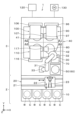
- FIG. 1 is a plan view showing an outline of a configuration of a grinding device according to an embodiment of the present invention
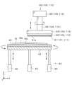
- FIG. 4 is a side view showing an example of the configuration of a grinding unit and a chuck.
- FIG. 2 is a flow chart showing a series of wafer processing steps performed by the grinding device.
- FIG. 4 is an explanatory diagram showing the state of rough grinding in a rough grinding section.
- FIG. 11 is an explanatory diagram for explaining a method for calculating a setup position.
- FIG. 13 is an explanatory diagram showing a state in which a setup position is updated.
- FIG. 13 is an explanatory diagram showing an upper limit position and a lower limit position of the setup position after updating the setup position when the setup position is updated.
- FIG. 13 is an explanatory diagram showing an upper limit position and a lower limit position of the setup position after updating the setup position when the setup position is updated.
- the back surface of a semiconductor substrate (hereafter referred to as a wafer) is ground to thin the wafer.
- Wafer grinding is performed, for example, by lowering a grinding wheel onto a wafer held in a chuck and rotating the grinding wheel to bring it into contact with the back surface of the wafer. During this process, the grinding wheel wears down and becomes thinner as the wafer is repeatedly ground. Therefore, in the grinding machine disclosed in Patent Document 1, for example, the spindle feed mechanism is controlled to move the grinding wheel closer to the wafer by an amount equal to the amount of wear on the grinding wheel.
- the setup position is the height position where the position of the top surface of the chuck and the position of the grinding surface of the grinding wheel coincide, or a position a set distance away from that height position.
- the grinding wheel wears out when the wafer is ground, so the setup position is adjusted and updated each time the wafer is ground.
- the position of the grinding wheel when wafer grinding is completed (spark out, described later) and the thickness of the wafer after grinding are measured, and the setup position is updated based on the measured position of the grinding wheel and the thickness of the wafer.
- the air cut start position, described later, before starting wafer grinding is then determined based on the setup position.
- the setup position cannot be updated properly. For example, if the wafer thickness is erroneously measured to be greater than the actual thickness, the length of the grinding wheel will be calculated to be shorter than the actual thickness, so the setup position for the next wafer will be lower than the actual position, which may result in a collision between the next wafer and the grinding wheel. Also, for example, if the wafer thickness is erroneously measured to be smaller than the actual thickness, the length of the grinding wheel will be calculated to be longer than the actual thickness, so the setup position for the next wafer will be higher than the actual position, which may result in a decrease in throughput for the next wafer.
- a wafer W serving as a substrate is ground to thin it.
- the wafer W is, for example, a semiconductor wafer such as a silicon wafer or a compound semiconductor wafer.
- the front surface Wa is a holding surface that is held by a chuck 42 (described later) in the grinding device 1.
- the back surface Wb of the wafer W, which is opposite the front surface Wa, is a grinding surface that is ground in the grinding device 1.
- the grinding device 1 has a configuration in which a loading/unloading station 2 and a processing station 3 are connected together.
- a loading/unloading station 2 for example, a cassette C capable of housing multiple wafers W is loaded and unloaded between the loading/unloading station 2 and the outside.
- the processing station 3 is equipped with various processing devices that perform the desired processing on the wafers W.
- a cassette mounting table 10 is provided in the loading/unloading station 2.
- a wafer transport area 20 is provided adjacent to the cassette mounting table 10 on the positive Y-axis side of the cassette mounting table 10.
- a wafer transport device 22 is provided that is movable on a transport path 21 extending in the X-axis direction.
- the wafer transport device 22 has a transport fork 23 that holds and transports a wafer W.
- the transport fork 23 is configured to be movable horizontally, vertically, around a horizontal axis, and around a vertical axis.
- the wafer transport device 22 is configured to be able to transport the wafer W to the cassette C on the cassette mounting table 10, the alignment section 50 described below, and the first cleaning section 60 described below.
- Processing station 3 processing such as grinding and cleaning is performed on the wafer W.
- Processing station 3 has a transfer section 30 that transfers the wafer W, a grinding unit 40 that performs grinding processing on the wafer W, an alignment section 50 that adjusts the horizontal orientation of the wafer W, and a first cleaning section 60 and a second cleaning section 70 that clean the wafer W after grinding.
- the transport unit 30 is an articulated robot equipped with multiple, for example three, arms 31. Each of the three arms 31 is configured to be freely rotatable. A transport pad 32 that suctions and holds the wafer W is attached to the arm 31 at the tip. The arm 31 at the base end is attached to a lifting mechanism 33 that raises and lowers the arm 31 in the vertical direction.
- the transport unit 30 is configured to be able to transport the wafer W to the grinding unit 40, the alignment unit 50, the first cleaning unit 60, and the second cleaning unit 70.
- the grinding unit 40 has a rotating table 41. On the rotating table 41, four chucks 42 are provided as substrate holders that suction-hold the wafer W. For example, a porous chuck is used as the chuck 42.
- the surface of the chuck 42 i.e., the holding surface for the wafer W, has a convex shape in which the center protrudes compared to the ends when viewed from the side. Note that this protrusion in the center is very small, but in the following explanation, the protrusion in the center of the chuck 42 is illustrated enlarged for clarity.
- the four chucks 42 are held by the four chuck bases 43, respectively.
- the chuck base 43 is provided with a tilt adjustment mechanism 44 that adjusts the relative tilt between each grinding section (rough grinding section 90, medium grinding section 100, and finish grinding section 110, described later) and the chuck 42.
- the tilt adjustment mechanism 44 has a fixed shaft 45 provided on the underside of the chuck base 43 and multiple, for example, two, lifting shafts 46. Each lifting shaft 46 is configured to be freely retractable, and raises and lowers the chuck base 43.
- This tilt adjustment mechanism 44 tilts the chuck 42 and chuck base 43 by raising and lowering the other end in the vertical direction by the lifting shaft 46, with one end of the outer periphery of the chuck base 43 (the position corresponding to the fixed shaft 45) as the base point. This makes it possible to adjust the relative tilt between the grinding surface of each grinding section at the processing positions A1 to A3 and the upper surface of the chuck 42.
- the configuration of the tilt adjustment mechanism 44 is not limited to this, but may be any mechanism capable of adjusting the relative angle (parallelism) of the surface (holding surface) of the chuck 42 with respect to the grinding surface of each grinding section.
- each of the four chucks 42 can be moved to the transfer position A0 and the processing positions A1 to A3 by rotating the rotary table 41.
- each of the four chucks 42 is configured to be rotatable around a vertical axis by a rotation mechanism (not shown).
- the transfer unit 30 transfers the wafer W.
- a thickness measuring unit 80 is provided to measure the thickness of the wafer W before or after grinding.
- the thickness measuring unit 80 measures the thickness of the wafer W at multiple points, for example, three points equally spaced radially (center point, middle point, and outer periphery point).
- the thickness measuring unit 80 also obtains the in-plane distribution of the thickness of the wafer W and calculates the flatness of the wafer W (TTV: Total Thickness Variation).
- the thickness measuring unit 80 may have any configuration, but may, for example, include a non-contact sensor (not shown) and a calculation unit (not shown).
- the thickness measuring unit 80 is provided at the transfer position A0, but the location of the thickness measuring unit 80 is not limited to this.
- the thickness measuring unit 80 may be located independently of the grinding unit 40.
- the rough grinding unit 90 is located at processing position A1 and performs rough grinding of the wafer W.
- the medium grinding unit 100 is located at processing position A2 and performs medium grinding of the wafer W.
- the finish grinding unit 110 is located at processing position A3 and performs finish grinding of the wafer W.
- the rough grinding unit 90 at the processing position A1 has an annular rough grinding wheel 91, a rough grinding wheel 92 that supports the rough grinding wheel 91, a mount 93 that supports the rough grinding wheel 92, a spindle 94 that rotates the rough grinding wheel 92 via the mount 93, and a drive unit 95 that supports the spindle 94.
- the drive unit 95 has, for example, a built-in motor (not shown) and rotates the spindle 94.
- the rough grinding unit 90 is configured to be movable vertically along a support 96 by the drive unit 95. Note that in this embodiment, the drive unit 95 and the support 96 constitute the movement mechanism of the present disclosure that moves the rough grinding wheel 91.
- the drive unit 95 uses a measurement unit (not shown) that measures the Z-axis position of the motor to measure the position of the rough grinding wheel 91 at the time of spark-out described below, specifically the boundary position between the lower surface of the mount 93 and the upper surface of the rough grinding wheel 92, and constitutes the first measurement unit of the present disclosure.
- the holding surface of the chuck 42 has a convex shape. Therefore, when grinding the wafer W using the rough grinding unit 90, a part of the annular rough grinding wheel 91 comes into contact with the wafer W. More specifically, the annular rough grinding wheel 91 comes into contact with the wafer W in an arc shape from the center to the outer peripheral edge. In this state, the chuck 42 and the rough grinding wheel 92 are each rotated, whereby the entire back surface Wb of the wafer W is ground.
- a thickness measuring unit 97 is provided at processing position A1 as a second measuring unit in this disclosure, which measures the thickness of the wafer W.
- the thickness measuring unit 97 may have any configuration, but may, for example, include a non-contact sensor (not shown) and a calculation unit (not shown).
- the medium grinding section 100 at processing position A2 has the same configuration as the rough grinding section 90. That is, as shown in FIG. 2, the medium grinding section 100 has an annular medium grinding stone 101, a medium grinding wheel 102, a mount 103, a spindle 104, a drive unit 105, and a support 106.
- the grain size of the abrasive grains of the medium grinding stone is smaller than the grain size of the abrasive grains of the rough grinding stone.
- a thickness measuring unit 107 is provided at processing position A2 as a second measuring unit in the present disclosure, which measures the thickness of the wafer W.
- the thickness measuring unit 107 may have any configuration, but may include, for example, a non-contact sensor (not shown) and a calculation unit (not shown).
- the finish grinding section 110 at processing position A3 has a configuration similar to that of the rough grinding section 90. That is, as shown in FIG. 2, the finish grinding section 110 has an annular finish grinding stone 111, a finish grinding wheel 112, a mount 113, a spindle 114, a drive section 115, and a support 116.
- the grain size of the abrasive grains of the finish grinding stone is smaller than that of the medium grinding stone.
- a thickness measuring unit 117 is provided at processing position A3 as a second measuring unit in this disclosure, which measures the thickness of the wafer W.
- the thickness measuring unit 117 may have any configuration, but may, for example, include a non-contact sensor (not shown) and a calculation unit (not shown).
- the grinding device 1 described above is provided with a display panel 120.
- the display panel 120 is, for example, a monitor or a touch panel, and may be directly attached to the grinding device 1 or may be one that can be viewed remotely.
- a selection screen for enabling or disabling the update of the setup position, which will be described later, is displayed on the display panel 120, and the operator can set it to enabled or disabled from the selection screen of the display panel 120.
- the display panel 120 may also display an input screen for the upper and lower limit positions of the setup position, which will be described later, or an input screen for the upper and lower limits of the amount of movement from the setup position.
- the upper and lower limit positions of the setup position can also be controlled by information set by the control unit 130 based on the amount of grinding, and this set information may be input from the input screen of the display panel 120.
- the grinding device 1 described above is provided with at least one control unit 130.
- the control unit 130 processes computer-executable instructions that cause the grinding device 1 to perform the various steps described in this disclosure.
- the control unit 130 may be configured to control each element of the grinding device 1 to perform the various steps described herein. In one embodiment, a part or all of the control unit 130 may be included in the grinding device 1.
- the control unit 130 may include a processing unit, a storage unit, and a communication interface.
- the control unit 130 is realized, for example, by a computer.
- the processing unit may be configured to read a program that provides logic or routines that enable various control operations to be performed from the storage unit, and to perform various control operations by executing the read program.
- This program may be stored in the storage unit in advance, or may be acquired via a medium when necessary.
- the acquired program is stored in the storage unit, and is read from the storage unit by the processing unit and executed.
- the medium may be various computer-readable storage media, or may be a communication line connected to the communication interface.
- the storage medium may be temporary or non-temporary.
- the processing unit may be a CPU (Central Processing Unit) or one or more circuits.
- the storage unit may include a RAM (Random Access Memory), a ROM (Read Only Memory), a HDD (Hard Disk Drive), an SSD (Solid State Drive), or a combination thereof.
- the communication interface may communicate with the grinding device 1 via a communication line such as a LAN (Local Area Network).
- a cassette C containing multiple wafers W is placed on the cassette mounting table 10 of the loading/unloading station 2.
- the wafers W in the cassette C are removed by the transport fork 23 of the wafer transport device 22 and transported to the processing station 3.
- the wafers W transported to the processing station 3 are delivered to the alignment section 50.
- the horizontal orientation of the wafer W is adjusted by adjusting the position of a notch portion (not shown) formed in the wafer W (S1 in FIG. 3).
- the wafer W is transported by the transport unit 30 from the alignment unit 50 to the grinding unit 40 and delivered to the chuck 42 at the delivery position A0.
- the thickness of the wafer W before grinding is measured at multiple points by the thickness measuring unit 80 (S2 in FIG. 3). The measured thickness is output to, for example, the control unit 130.
- the wafer W held by the chuck 42 is moved to the processing position A1.
- the air cut start position which will be described later, is adjusted in the rough grinding section 90 (S3 in FIG. 3).
- the air cut start position may be adjusted based on the thickness of the wafer W before grinding measured in S2, or the thickness of the wafer W before rough grinding may be measured by the thickness measuring section 97 in S3, and the air cut start position may be adjusted based on the measured thickness.
- the method of adjusting the air cut start position will be described in detail later.
- the left diagram in FIG. 4 is an explanatory diagram showing the positional relationship between the rough grinding wheel 91 and the wafer W during rough grinding.
- the right diagram in FIG. 4 is a graph showing the time series change in the height position of the rough grinding wheel 91, with the vertical axis representing the height position of the grinding surface 91a of the rough grinding wheel 91 and the horizontal axis representing time.
- the rough grinding wheel 91 (and the rough grinding wheel 92) is lowered at high speed from the standby position H1 to the air cut start position H2 (time T0 to T1). At this time, it is lowered at high speed from the viewpoint of improving throughput. However, if the rough grinding wheel 91 is brought into contact with the wafer W at this speed, there is a risk that the rough grinding wheel 91 will be broken or the wafer W will be damaged. For this reason, the rough grinding wheel 91 is then decelerated and lowered at low speed to the contact position H3 with the wafer W (time T1 to T2: air cut).
- the rough grinding wheel 91 is further lowered to grind the wafer W to the grinding end position H4 in the rough grinding section 90 (the target thickness of the wafer W in the rough grinding section 90) (times T2 to T5: grinding step).
- the descent speed of the rough grinding wheel 91 may be changed stepwise between times T2 and T5 (e.g., times T3 and T4), or the descent speed may be controlled to be constant.
- the height position of the rough grinding wheel 91 is kept waiting at the grinding end position H4 for a certain period of time (time T5 to T6: spark out).
- time T5 to T6 spark out
- the rough grinding wheel 91 continues to rotate.
- the position of the rough grinding wheel 91 specifically the boundary position between the bottom surface of the mount 93 and the top surface of the rough grinding wheel 92 (hereinafter referred to as the Z position) is measured from the Z axis position of the motor of the drive unit 95 (S5 in Figure 3).
- the measured Z position is output to, for example, the control unit 130.
- the rough grinding wheel 91 starts to rise while continuing to rotate (time T6 to T7: escape cut).
- time T6 to T7 escape cut
- the rough grinding wheel 91 is raised at a low speed to prevent wheel marks from remaining on the back surface Wb of the wafer W when the wafer W and the rough grinding wheel 91 are separated from each other.
- the rough grinding wheel 91 is accelerated and moved to the standby position H1 (after time T7), and rough grinding of the back surface Wb of the wafer W in the rough grinding section 90 is completed.
- the thickness of the wafer W after rough grinding is measured by the thickness measuring unit 97 (S6 in FIG. 3).
- the measured thickness is output to, for example, the control unit 130. Note that the thickness measurement of the wafer W by the thickness measuring unit 97 is also performed during rough grinding.
- the setup position is adjusted when grinding the next wafer W in the rough grinding section 90.
- the setup position is a height position where the position of the upper surface of the chuck 42 and the position of the grinding surface of the rough grinding wheel 91 coincide.
- the setup position may be a position a specified distance away from the above height position. The specified distance can be set arbitrarily. The method of adjusting the setup position will be described in detail later. The adjustment of the setup position is performed before grinding the next wafer W to be processed with the same chuck 42 and the same processing position A1.
- the wafer W held by the chuck 42 is moved to the processing position A2.
- the air cut start position is adjusted in the intermediate grinding section 100 (S8 in FIG. 3).
- the thickness of the wafer W before intermediate grinding is measured by the thickness measuring section 107, and the air cut start position is adjusted based on the measured thickness.
- the back surface Wb of the wafer W is medium-ground by the medium grinding unit 100 (S9 in FIG. 3).
- the medium grinding by the medium grinding unit 100 is performed, for example, in the same manner as the rough grinding by the rough grinding unit 90 shown in FIG. 4. That is, by controlling the height position of the medium grinding wheel 101, air cut, grinding step, spark out, and escape cut are performed in sequence.
- the Z position is measured at the time of spark out (S10 in FIG. 3). The measured Z position is output, for example, to the control unit 130.
- the thickness of the wafer W after intermediate grinding is measured by the thickness measuring unit 107 (S11 in FIG. 3).
- the measured thickness is output to, for example, the control unit 130. Note that the thickness measurement of the wafer W by the thickness measuring unit 107 is also performed during intermediate grinding.
- the setup position is adjusted (S12 in FIG. 3).
- the setup position is adjusted when grinding the next wafer W in the intermediate grinding section 100.
- the wafer W held by the chuck 42 is moved to the processing position A3.
- the air cut start position is adjusted in the finish grinding section 110 (S13 in FIG. 3).
- the thickness of the wafer W before finish grinding is measured by the thickness measuring section 117, and the air cut start position is adjusted based on the measured thickness.
- the back surface Wb of the wafer W is finish-ground by the finish grinding unit 110 (S14 in FIG. 3).
- the finish grinding by the finish grinding unit 110 is performed, for example, in the same manner as the rough grinding by the rough grinding unit 90 shown in FIG. 4. That is, by controlling the height position of the finish grinding wheel 111, air cut, grinding step, spark out, and escape cut are performed in sequence.
- the Z position is measured at the time of spark out (S15 in FIG. 3). The measured Z position is output, for example, to the control unit 130.
- the thickness of the wafer W after finish grinding is measured by the thickness measuring unit 117 (S16 in FIG. 3).
- the measured thickness is output to, for example, the control unit 130. Note that the thickness measurement of the wafer W by the thickness measuring unit 117 is also performed during finish grinding.
- the setup position is adjusted (S117 in FIG. 3).
- the setup position is adjusted when grinding the next wafer W in the finish grinding section 110.
- the wafer W held by the chuck 42 is moved to the transfer position A0.
- the thickness of the wafer W after finish grinding is measured at multiple points by the thickness measuring unit 80, the in-plane distribution of the thickness of the wafer W is obtained, and the flatness of the wafer W is obtained (S18 in FIG. 3).
- the obtained thickness distribution and flatness are output to, for example, the control unit 130.
- the wafer W is transported by the transport unit 30 from the transfer position A0 to the second cleaning unit 70, and the front surface Wa and/or back surface Wb are cleaned while held on the transport pad 32 (S19 in FIG. 3).
- the wafer W is transported by the transport unit 30 from the second cleaning unit 70 to the first cleaning unit 60, and the front surface Wa and/or back surface Wb are further cleaned using a cleaning liquid nozzle (not shown) (S20 in FIG. 3).
- the wafer W that has been subjected to all the processes is transferred to the cassette C on the cassette mounting table 10 by the transfer fork 23 of the wafer transfer device 22.
- the series of wafer processes is completed. Note that in the grinding device 1, the series of wafer processes are continuously performed on the multiple wafers W stored in the cassette C.
- a method for adjusting the setup position will be described.
- a case will be described in which a third setup position P3 for a third wafer W3 is adjusted and updated using a first setup position P1 for a first wafer W1 and a second setup position P2 for a second wafer W2.
- FIG. 5 is an explanatory diagram for explaining a method for calculating the setup position.
- FIG. 5(a) shows the state of spark out during rough grinding of the first wafer W1
- FIG. 5(b) shows the state of spark out during rough grinding of the second wafer W2.
- Z1 and Z2 are Z positions (the position of the rough grinding wheel 91 calculated from the Z-axis position of the motor of the driving unit 95, specifically, the boundary position between the lower surface of the mount 93 and the upper surface of the rough grinding wheel 92).
- D1 and D2 are the lengths of the rough grinding wheel 91 including the rough grinding wheel 92.
- T1 and T2 are the thicknesses of the wafers W1 and W2 after rough grinding, respectively.
- the distance from the home position at the upper end of the Z position to the holding surface of the chuck 42 is constant, and the following formula (1) is established.
- Z1+D1+T1 Z2+D2+T2...(1)
- FIG. 6 is an explanatory diagram showing how the setup position is updated.
- Fig. 6(a) shows the second setup position P2
- Fig. 6(b) shows the third setup position P3.
- the movement amount M from the second setup position P2 to the third setup position P3 is the amount of wear (D1-D2) caused when the rough grinding wheel 91 wears down due to rough grinding of the second wafer W2. That is, the movement amount M of the setup position is calculated by the following formula (2) by modifying the above formula (1).
- the third setup position P3 for the third wafer W3 is adjusted and updated based on the Z positions Z1, Z2 of the wafers W1, W2 at the time of spark-out measured in S5 and the thicknesses T1, T2 of the wafers W1, W2 measured in S6 (S3).
- the air cut start position is the height position of the grinding surface 91a of the rough grinding wheel 91 when air cut starts, and is the air cut start position H2 shown in FIG. 4.
- the air cut start position is set by adding the thickness of the second wafer W2 before rough grinding and the air cut amount to the first setup position P1. In this case, the air cut start position is set to an amount that is as small as possible without causing the rough grinding wheel 91 to collide with the second wafer W2.
- the thickness of the second wafer W2 before rough grinding may be measured by the thickness measuring unit 80 in S2, or may be measured by the thickness measuring unit 97 in S3.
- the air cut amount is set in advance in a recipe, and is the descending distance when the rough grinding wheel 91 descends from the air cut start position H2 to the contact position H3 shown in FIG. 4.
- S2 may be omitted and the thickness measurement unit 80 may not measure the thickness of the second wafer W2 before rough grinding, or the thickness measurement unit 80 may not measure the thickness of the second wafer W2 before rough grinding in S3.
- the air cut start position of the second wafer W2 is adjusted based on the thickness of the second wafer W2 that is assumed in advance.
- the setup positions are adjusted in the rough grinding section 90, the medium grinding section 100, and the finish grinding section 110.
- the grinding wheels can be appropriately positioned before grinding. This allows the back surface Wb of the wafer W to be appropriately ground (rough grinding, medium grinding, and finish grinding).
- the air cut start position is adjusted in each of the rough grinding section 90, the medium grinding section 100, and the finish grinding section 110. For example, when the grinding wheel wears out, the air cut start position becomes higher, and it takes time for the grinding wheel to reach the wafer W. In this regard, according to this embodiment, even if the grinding wheel wears out, the air cut start position can be appropriately adjusted to shorten the time required for air cut and improve throughput.
- the thickness measurement of the wafer W after rough grinding in S6 is not performed properly. For example, if the measured thickness value of the wafer W measured in S6 differs from the set thickness, a warning (alarm) is issued. Furthermore, if the measured thickness value differs from the set thickness in this way, an upper and lower tolerance range is set for the set thickness, and if the measured thickness value falls outside the tolerance range, rough grinding of the next wafer W is stopped.
- the measured thickness of the wafer W measured in S6 is the same as the set thickness but different from the actual thickness, it may not be possible to properly adjust and update the setup position of the rough grinding unit 90 in S3.
- the setup position is set to a position lower than the actual length, which may cause the rough grinding wheel 91 and the wafer W to collide, causing the rough grinding wheel 91 to break or the wafer W to be damaged.
- the setup position will be set to a position higher than the actual length, which may result in a longer time required for air cutting, resulting in a decrease in throughput.
- upper and lower limits are set for the movement of the setup position.
- the upper and lower limits for the movement of the setup position are set in each of the rough grinding unit 90, the medium grinding unit 100, and the finish grinding unit 110.
- a method for setting the upper and lower limits for the movement of the setup position in the rough grinding unit 90 will be explained, but the same applies to the medium grinding unit 100 and the finish grinding unit 110.
- the upper limit position PU is a position moved upward from the setup position P by an upper limit of the movement amount M U (upper limit threshold).
- the lower limit position PL is a position moved downward from the setup position P by a lower limit of the movement amount M L (lower limit threshold).
- the upper limit MU of the movement amount of the setup position P is set based on the rough grinding amount of the wafer W.
- the upper limit MU is calculated by multiplying the rough grinding amount of the wafer W set by the recipe by an arbitrarily set ratio (%).
- the ratio can be set in any manner, but for example, an allowable range of 0%-200% may be set and the operator may set it arbitrarily. For example, when the rough grinding amount of the wafer W is 30 ⁇ m and the set ratio is 10%, the upper limit MU is set to 3 ⁇ m.
- the lower limit ML of the movement amount of the setup position P is also set based on the rough grinding amount of the wafer W.
- the lower limit ML is calculated by multiplying the rough grinding amount of the wafer W, which is set by the recipe, by an arbitrarily set percentage (%).
- the movement amount M of the setup position is calculated from the above formula (2) based on the Z position at the time of spark-out of the wafer W measured in S5 and the thickness of the wafer measured in S6. If the upward movement amount M during this automatic update is larger than the upper limit M U , or if the downward movement amount M during the automatic update is smaller than the lower limit M L , a warning is issued. This warning stops rough grinding of the subsequent wafer W.
- the setup position P can be appropriately updated between the upper limit position PU and the lower limit position PL .
- the setup position P can be appropriately updated between the upper limit position PU and the lower limit position PL .
- the setup position is updated in S3, that is, if the setup position is moved downward in response to wear of the rough grinding wheel 91, the possibility of the above-mentioned collision between the rough grinding wheel 91 and the wafer W increases.
- the update of the setup position of the rough grinding unit 90 in S3 is disabled.
- the validity or invalidity of the update of the setup position may be determined by the operator, or may be determined by the control unit 130 based on the thickness of the wafer W that has been determined in advance.
- the update of the setup position may be enabled or disabled by comparing the thickness of the wafer W before grinding with the amount of air cut. If the surface height (height of the back surface Wb) of the wafer W before grinding is expected to be higher than the air cut start position or the height of the rough grinding wheel 91 in the air cut range (contact position H3 shown in FIG. 4), the update of the setup position is disabled.
- the above grinding device 1 has a three-axis configuration with a rough grinding section 90, a medium grinding section 100, and a finish grinding section 110, but it may have a one-axis or two-axis configuration. Whether it is a one-axis or two-axis configuration, the technology disclosed herein can be applied to each grinding section.
Landscapes
- Engineering & Computer Science (AREA)
- Mechanical Engineering (AREA)
- Mechanical Treatment Of Semiconductor (AREA)
- Grinding And Polishing Of Tertiary Curved Surfaces And Surfaces With Complex Shapes (AREA)
Priority Applications (1)
| Application Number | Priority Date | Filing Date | Title |
|---|---|---|---|
| JP2025501069A JPWO2024171883A1 (https=) | 2023-02-17 | 2024-02-06 |
Applications Claiming Priority (2)
| Application Number | Priority Date | Filing Date | Title |
|---|---|---|---|
| JP2023-023242 | 2023-02-17 | ||
| JP2023023242 | 2023-02-17 |
Publications (1)
| Publication Number | Publication Date |
|---|---|
| WO2024171883A1 true WO2024171883A1 (ja) | 2024-08-22 |
Family
ID=92421765
Family Applications (1)
| Application Number | Title | Priority Date | Filing Date |
|---|---|---|---|
| PCT/JP2024/003849 Ceased WO2024171883A1 (ja) | 2023-02-17 | 2024-02-06 | 研削方法及び研削装置 |
Country Status (3)
| Country | Link |
|---|---|
| JP (1) | JPWO2024171883A1 (https=) |
| TW (1) | TW202438231A (https=) |
| WO (1) | WO2024171883A1 (https=) |
Families Citing this family (1)
| Publication number | Priority date | Publication date | Assignee | Title |
|---|---|---|---|---|
| TWI908478B (zh) * | 2024-11-20 | 2025-12-11 | 廣運機械工程股份有限公司 | 晶錠晶圓研磨系統 |
Citations (4)
| Publication number | Priority date | Publication date | Assignee | Title |
|---|---|---|---|---|
| JP2001277084A (ja) * | 2000-03-28 | 2001-10-09 | Nippei Toyama Corp | 両頭研削盤 |
| JP2013136106A (ja) * | 2011-12-28 | 2013-07-11 | Ntn Corp | 研削盤の測定異常機能付き加工径測定装置 |
| JP2014144513A (ja) * | 2013-01-30 | 2014-08-14 | Komatsu Ntc Ltd | 研削加工方法 |
| JP2019155488A (ja) * | 2018-03-07 | 2019-09-19 | 株式会社東京精密 | 研削盤 |
-
2024
- 2024-02-06 JP JP2025501069A patent/JPWO2024171883A1/ja active Pending
- 2024-02-06 WO PCT/JP2024/003849 patent/WO2024171883A1/ja not_active Ceased
- 2024-02-06 TW TW113104592A patent/TW202438231A/zh unknown
Patent Citations (4)
| Publication number | Priority date | Publication date | Assignee | Title |
|---|---|---|---|---|
| JP2001277084A (ja) * | 2000-03-28 | 2001-10-09 | Nippei Toyama Corp | 両頭研削盤 |
| JP2013136106A (ja) * | 2011-12-28 | 2013-07-11 | Ntn Corp | 研削盤の測定異常機能付き加工径測定装置 |
| JP2014144513A (ja) * | 2013-01-30 | 2014-08-14 | Komatsu Ntc Ltd | 研削加工方法 |
| JP2019155488A (ja) * | 2018-03-07 | 2019-09-19 | 株式会社東京精密 | 研削盤 |
Also Published As
| Publication number | Publication date |
|---|---|
| JPWO2024171883A1 (https=) | 2024-08-22 |
| TW202438231A (zh) | 2024-10-01 |
Similar Documents
| Publication | Publication Date | Title |
|---|---|---|
| JP6877585B2 (ja) | 基板処理システム、基板処理方法及びコンピュータ記憶媒体 | |
| JP6937370B2 (ja) | 研削装置、研削方法及びコンピュータ記憶媒体 | |
| WO2018235619A1 (ja) | 基板処理システム、基板処理方法及びコンピュータ記憶媒体 | |
| KR20220097497A (ko) | 기판 처리 방법 및 기판 처리 장치 | |
| WO2024171883A1 (ja) | 研削方法及び研削装置 | |
| CN112123063B (zh) | 被加工物的加工方法 | |
| JP7526611B2 (ja) | 加工システム及び加工方法 | |
| JP4966069B2 (ja) | 加工装置 | |
| JP2022018648A (ja) | 基板処理装置及び記憶媒体 | |
| JP7653269B2 (ja) | 処理方法及び処理装置 | |
| CN112454161A (zh) | 研削装置及研削方法 | |
| KR20240064527A (ko) | 가공 장치 | |
| CN115066314B (zh) | 加工方法以及加工装置 | |
| JP2023171984A (ja) | 研削装置及びウェーハの研削方法 | |
| JP2025072198A (ja) | 研削方法及び研削装置 | |
| CN116075394A (zh) | 加工装置和加工方法 | |
| WO2021095588A1 (ja) | 基板処理方法及び基板処理装置 | |
| WO2025013260A1 (ja) | 研削方法、刃先残量の算出方法及び研削装置 | |
| US20260124714A1 (en) | Processing method and processing apparatus | |
| WO2024171822A1 (ja) | 研削装置、傾き調整方法及び情報表示部 | |
| JP2025173438A (ja) | 加工装置、及び、加工装置の異常判定方法。 | |
| KR20250164793A (ko) | 두께 측정부의 위치 설정 방법 및 연삭 장치 | |
| JP2026006787A (ja) | 研削装置 | |
| WO2025027806A1 (ja) | 研削装置及び研削方法 | |
| JP2025173437A (ja) | 加工装置、及び、加工装置の異常判定方法。 |
Legal Events
| Date | Code | Title | Description |
|---|---|---|---|
| 121 | Ep: the epo has been informed by wipo that ep was designated in this application |
Ref document number: 24756733 Country of ref document: EP Kind code of ref document: A1 |
|
| ENP | Entry into the national phase |
Ref document number: 2025501069 Country of ref document: JP Kind code of ref document: A |
|
| WWE | Wipo information: entry into national phase |
Ref document number: 2025501069 Country of ref document: JP |
|
| NENP | Non-entry into the national phase |
Ref country code: DE |
|
| 122 | Ep: pct application non-entry in european phase |
Ref document number: 24756733 Country of ref document: EP Kind code of ref document: A1 |