WO2024171835A1 - マルチコアファイバ - Google Patents
マルチコアファイバ Download PDFInfo
- Publication number
- WO2024171835A1 WO2024171835A1 PCT/JP2024/003354 JP2024003354W WO2024171835A1 WO 2024171835 A1 WO2024171835 A1 WO 2024171835A1 JP 2024003354 W JP2024003354 W JP 2024003354W WO 2024171835 A1 WO2024171835 A1 WO 2024171835A1
- Authority
- WO
- WIPO (PCT)
- Prior art keywords
- peripheral surface
- outer peripheral
- core
- cladding
- multicore fiber
- Prior art date
- Legal status (The legal status is an assumption and is not a legal conclusion. Google has not performed a legal analysis and makes no representation as to the accuracy of the status listed.)
- Ceased
Links
Images




Classifications
-
- G—PHYSICS
- G02—OPTICS
- G02B—OPTICAL ELEMENTS, SYSTEMS OR APPARATUS
- G02B6/00—Light guides; Structural details of arrangements comprising light guides and other optical elements, e.g. couplings
- G02B6/02—Optical fibres with cladding with or without a coating
- G02B6/02042—Multicore optical fibres
Definitions
- the present invention relates to a multicore fiber.
- Multicore fibers in which the outer circumference of multiple cores is surrounded by a single cladding, are being used. Multicore fibers can transmit multiple signals using light propagating through each of the multiple cores, which increases the transmission capacity per optical fiber.
- a multicore fiber When a multicore fiber is used for long-distance optical signal transmission, it may be connected to another multicore fiber. In this case, it is desirable to improve the placement accuracy of each core of the multicore fiber in order to reduce the loss of light at the connection part of the multicore fiber.
- Patent Document 1 describes a multicore fiber in which the cladding has a noncircular outer shape in order to achieve good optical coupling.
- Patent Document 1 describes a multicore fiber having a cladding with a so-called D-shaped outer shape in which part of the outer circumferential surface is formed into a flat shape.
- the alignment may be performed by side-view alignment, in which light is irradiated from the side of the cladding to observe the positions of the cores, etc.
- side-view alignment in which light is irradiated from the side of the cladding to observe the positions of the cores, etc.
- An example of such a rotational position is a position where light is incident from a flat portion of the outer circumferential surface of the cladding. For this reason, alignment may be difficult.
- the present invention aims to provide a multicore fiber that can be easily aligned.
- Aspect 1 of the present invention for solving the above problem is a multi-core fiber comprising a plurality of cores and a cladding surrounding the cores, the outer surface of the cladding having a first outer surface which is a portion in the circumferential direction and a second outer surface which is another portion in the circumferential direction, and at least a portion of the first outer surface bulges outward from the cladding with a larger radius of curvature than the second outer surface.
- the multicore fiber of the present invention can be easily aligned.
- Aspect 2 of the present invention is a multicore fiber according to aspect 1, characterized in that a plurality of the cores are arranged on the outer circumferential side of the cladding, and at least one of the portions of the outer circumferential surface facing the plurality of the cores is the first outer circumferential surface.
- the portion of the outer circumferential surface facing the core is the portion of the outer circumferential surface closest to the core. Therefore, the distance between the core arranged on the outer circumferential side and the first outer circumferential surface facing the core is smaller than the distance between the core and the second outer circumferential surface when the portion of the outer circumferential surface facing the core arranged on the outer circumferential side is the second outer circumferential surface. Therefore, unnecessary higher-order mode light propagating through the core facing the first outer circumferential surface can be attenuated by the influence of the first outer circumferential surface. Unnecessary higher-order mode light is, for example, light not used for communication.
- Aspect 3 of the present invention is the multi-core fiber of aspect 2, characterized in that each of the portions is the first outer circumferential surface.
- the influence of the first outer peripheral surface can attenuate unnecessary higher-order mode light propagating through each of the cores arranged on the outer peripheral side.
- Aspect 4 of the present invention is a multicore fiber according to any one of aspects 1 to 3, characterized in that the outer peripheral surface of the cladding has a non-rotationally symmetric shape.
- Aspect 5 of the present invention is a multicore fiber according to any one of aspects 1 to 4, characterized in that the radius of curvature of the first outer peripheral surface is 1.5 times or more and 20 times or less than the radius of curvature of the second outer peripheral surface.
- the present invention provides a multicore fiber that can be easily aligned.
- FIG. 1 is a diagram showing a cross section perpendicular to the longitudinal direction of a multi-core fiber according to a first embodiment of the present invention.
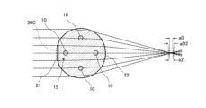
- FIG. 4 is a diagram showing spherical aberration when light is incident on the second outer surface from a direction perpendicular to the longitudinal direction of the multi-core fiber of FIG. 1 and is emitted from the first outer surface.
- 2 is a diagram showing spherical aberration when light is incident on a first outer surface from a direction perpendicular to the longitudinal direction of the multi-core fiber in FIG. 1 and is emitted from a second outer surface.
- 5 is a diagram showing a cross section perpendicular to the longitudinal direction of a multi-core fiber according to a second embodiment of the present invention.
- FIG. FIG. 11 is a diagram showing a cross section perpendicular to the longitudinal direction of a multi-core fiber according to a third embodiment of the present invention.
- FIG. 1 is a diagram showing a cross section perpendicular to the longitudinal direction of a multi-core fiber according to this embodiment.
- the multi-core fiber 1 of this embodiment includes a plurality of cores 10, a marker 15, a cladding 20 surrounding the outer circumferential surfaces of each of the cores 10 and the markers 15 without any gaps, an inner coating layer 31 coating the outer circumferential surface of the cladding 20, and an outer coating layer 32 coating the outer circumferential surface of the inner coating layer 31.
- an example having four cores 10 is shown.
- each core 10 is arranged on a circumference centered on a reference position 20R, which is approximately the center of the cladding 20. In this embodiment, each core 10 is arranged on the outermost side of the cladding 20. In the multicore fiber 1 of this embodiment, the distance between each core 10 is equal to each other, and each core 10 is arranged at a position that is approximately four-fold rotationally symmetric about the reference position 20R.
- the diameter of the core 10 is, for example, 4 ⁇ m or more and 14 ⁇ m or less.
- the markers 15 are arranged on the outside of the circumference on which each of the cores 10 is arranged.
- the refractive index of the markers 15 may be higher or lower than that of the cladding 20, provided that the refractive index is different from that of the cladding 20.
- each core 10 is higher than that of the cladding 20, and the relative refractive index difference of each core 10 with respect to the cladding 20 is, for example, 0.2% or more and 2.0% or less.
- a core 10 is made of silica glass doped with a dopant such as germanium that increases the refractive index
- the cladding 20 is made of silica glass with no dopant added.
- the core 10 may be made of silica glass with no dopant added
- the cladding 20 may be made of silica glass doped with a dopant such as fluorine that decreases the refractive index.
- the marker 15 is made of silica glass with a different refractive index from the cladding 20.
- the clad 20 has a non-circular outer shape, and has a first outer peripheral surface 21, which is a part in the circumferential direction, and a second outer peripheral surface 22, which is the other part in the circumferential direction.
- one of the parts of the outer peripheral surface of the clad 20 facing each core 10 is the first outer peripheral surface 21, and the other part of the outer peripheral surface of the clad 20 is the second outer peripheral surface 22.
- the part of the outer peripheral surface facing the core 10 is the part of the outer peripheral surface closest to the core 10. Therefore, the distance between the core 10 facing the first outer peripheral surface 21 and the first outer peripheral surface 21 is smaller than the distance between the core 10 and the second outer peripheral surface 22.
- the second outer peripheral surface 22 overlaps with a part of a predetermined circumference 20C centered on the reference position 20R of the clad 20.
- the circumference 20C shown by the dashed line and the second outer peripheral surface 22 are drawn slightly shifted.
- the first outer peripheral surface 21 bulges outward from the cladding 20 with a larger radius of curvature than the second outer peripheral surface 22 and is connected to the second outer peripheral surface 22. Therefore, the first outer peripheral surface 21 is located inside the circumference 20C.
- the length of the straight line connecting both ends of the first outer peripheral surface 21 is equal to or greater than the diameter of the core 10 that faces the first outer peripheral surface 21. Also, in this embodiment, when the first outer peripheral surface 21 is viewed along a direction perpendicular to the longitudinal direction of the multicore fiber 1, the core 10 that faces the first outer peripheral surface 21 completely overlaps the first outer peripheral surface 21.
- the first outer peripheral surface 21 is formed in only one location, so the outer peripheral surface of the cladding 20 has a rotationally asymmetric shape.
- the radius of curvature of the first outer peripheral surface 21 is preferably 1.5 to 20 times the radius of curvature of the second outer peripheral surface 22. In this way, by making the radius of curvature of the first outer peripheral surface 1.5 times or more the radius of curvature of the second outer peripheral surface, the outer peripheral surface of the cladding can become even closer to a flat surface. Therefore, rough alignment based on the outer peripheral surface of such cladding 20 can be performed even more easily. In addition, by making the radius of curvature of the first outer peripheral surface 20 times or less the radius of curvature of the second outer peripheral surface, spherical aberration can be suppressed when performing side view alignment.
- the inner coating layer 31 and the outer coating layer 32 are each made of a resin such as an ultraviolet-curable resin, and the inner coating layer 31 and the outer coating layer 32 are made of different resins.
- the multi-core fiber 1 of this embodiment by transmitting light through the multi-core fiber 1 of this embodiment as described above, it is possible to reduce the spherical aberration of a multi-core fiber having a circular cladding with a radius of curvature of the second outer peripheral surface, which is smaller than the spherical aberration of light when light is incident on the circular outer peripheral surface with a radius of curvature of the second outer peripheral surface from a direction perpendicular to the longitudinal direction of the circular cladding and the light is emitted from the circular outer peripheral surface, compared to when light is transmitted through the multi-core fiber. Since the spherical aberration of light is thus small, the multi-core fiber 1 can be aligned in the rotational direction with greater accuracy.
- FIG. 2 also shows the magnitude aD1 of spherical aberration when light is transmitted through a multicore fiber having a so-called D-shaped cladding in which the portion corresponding to the first outer peripheral surface 21 of the cladding is flat.
- this plane is indicated by a dotted line.
- the multicore fiber can be understood as a flat lens, and the magnitude aD1 of spherical aberration is smaller than the magnitude a1 of spherical aberration when light is transmitted through the multicore fiber 1 of this embodiment as described above.
- FIG. 3 is a diagram showing spherical aberration when light is incident on the first outer peripheral surface 21 from a direction perpendicular to the longitudinal direction of the multicore fiber 1 and emitted from the second outer peripheral surface 22.
- the multicore fiber 1 can be understood as a biconvex lens similar to a plano-convex lens, and the light emitted from the second outer peripheral surface 22 has a spherical aberration of magnitude a2.
- a plano-convex lens is a lens in which the surface on which light enters is formed flat and the surface from which light exits is formed convex.
- the magnitude a2 of the spherical aberration is larger than the magnitude a1 of the spherical aberration.
- FIG. 3 also shows the magnitude a0 of the spherical aberration when the same light is transmitted through a multicore fiber having a circular cladding. In this case, the magnitude a2 of the spherical aberration tends to be larger than the magnitude a0 of the spherical aberration.
- Figure 3 also shows the magnitude aD2 of spherical aberration when light is transmitted through a multicore fiber having a so-called D-shaped cladding in which the portion corresponding to the first outer peripheral surface 21 of the cladding is flat.
- this plane is indicated by a dotted line.
- the multicore fiber can be understood as a plano-convex lens, and the magnitude aD2 of spherical aberration is larger than the magnitude a2 of spherical aberration when light is transmitted through the multicore fiber 1 of this embodiment as described above.
- the first outer peripheral surface 21 may have a constant radius of curvature that overlaps with a portion of the circumference of a virtual circle not shown, or it may not have a constant radius of curvature.
- the shape of the first outer peripheral surface 21 may be a portion of an ellipse or a portion of a perfect circle.
- the multi-core fiber 1 of this embodiment alignment can be easily performed.
- the shape of the outer peripheral surface of the clad 20 is non-circular, rough alignment can be performed based on the outer shape of the clad 20 before side-view alignment.
- the alignment position can be determined to be one when performing the above-mentioned rough alignment, making alignment easier.
- the first outer surface 21 is a portion of the outer surface of the clad 20 that faces the core 10 arranged on the outer periphery. Therefore, the distance between the core 10 facing the first outer surface 21 and the first outer surface 21 is smaller than the distance between the core 10 facing the second outer surface 22 and the second outer surface 22.
- the multicore fiber 1 of this embodiment differs from the multicore fiber 1 of the first embodiment in that each of the portions of the outer surface of the cladding 20 that face the core 10 is designated as a first outer surface 21, and the other portions of the outer surface of the cladding 20 are designated as a second outer surface 22.
- each of the portions of the outer surface of the cladding 20 that face the cores 10 is the first outer surface 21, so that unnecessary higher-order mode light propagating through each core 10 can be attenuated by the influence of the first outer surface 21, compared to a multicore fiber having a circular cladding that overlaps with the second outer surface 22.
- the multicore fiber 1 of this embodiment differs from the multicore fiber 1 of the first embodiment in that the multiple cores 10 are arranged in a straight line.
- the cores 10 located at both ends are cores arranged on the outer periphery of the clad 20.
- each of the portions of the outer periphery of the clad 20 facing the cores 10 located at both ends is designated as a first outer periphery 21, and the other portions of the outer periphery of the clad 20 are designated as a second outer periphery 22.
- the shape of the outer periphery of the clad 20 may be the same as the shape of the outer periphery of the clad 20 in the first embodiment.
- first outer periphery 21 only one of the portions of the outer periphery of the clad 20 facing the cores 10 located at both ends is designated as the first outer periphery 21, and the other portions of the outer periphery of the clad 20 are designated as the second outer periphery 22.
- the present invention has been described above using the above embodiment as an example, but the present invention is not limited to this.
- the first outer peripheral surface 21 may be provided on the outer peripheral surface of the cladding 20 other than the portion facing the core 10.
- the first outer peripheral surface 21 may be provided at some of the multiple locations on the outer peripheral surface of the clad 20 that face the core 10.
- the multicore fiber 1 of the first embodiment is an example of this form.
- the first outer peripheral surface 21 may be provided at two or three of the four locations on the outer peripheral surface of the clad 20 that face the core 10. That is, some of the locations on the outer peripheral surface that face the core 10 arranged on the outer periphery of the clad 20 may be the first outer peripheral surface 21, and some of the other locations may be the second outer peripheral surface.
- all of the cores 10 are positioned on a circumference centered on the reference position 20R, but other cores may be positioned inside the circumference.
- a core may be positioned on the reference position 20R.
- the length of the straight line connecting both ends of the first outer peripheral surface 21 is equal to or greater than the diameter of the core 10 facing the first outer peripheral surface 21.
- the length of the straight line connecting both ends of the first outer peripheral surface 21 may be smaller than the diameter of the core 10.
- the length of the straight line connecting both ends of the first outer peripheral surface 21 is equal to or greater than the diameter of the core 10, higher-order mode light not required for communication can be absorbed more efficiently.
- the core 10 facing the first outer peripheral surface 21 when the first outer peripheral surface 21 is viewed along a direction perpendicular to the longitudinal direction of the multicore fiber 1, the core 10 facing the first outer peripheral surface 21 completely overlaps the first outer peripheral surface 21.
- a part of the core 10 facing the first outer peripheral surface 21 may overlap the first outer peripheral surface 21, and another part may not overlap the first outer peripheral surface 21.
- the core 10 facing the first outer peripheral surface 21 when the core 10 facing the first outer peripheral surface 21 completely overlaps the first outer peripheral surface 21, light in a higher mode that is not required for communication can be absorbed more efficiently.
- the present invention provides a multicore fiber that can be easily aligned, and can be used in the field of optical communications and other devices that use multicore fibers.
Landscapes
- Physics & Mathematics (AREA)
- General Physics & Mathematics (AREA)
- Optics & Photonics (AREA)
- Optical Couplings Of Light Guides (AREA)
Priority Applications (3)
| Application Number | Priority Date | Filing Date | Title |
|---|---|---|---|
| EP24756685.4A EP4667984A1 (en) | 2023-02-14 | 2024-02-01 | Multicore fiber |
| JP2025501049A JPWO2024171835A1 (https=) | 2023-02-14 | 2024-02-01 | |
| CN202480007592.1A CN120476331A (zh) | 2023-02-14 | 2024-02-01 | 多芯光纤 |
Applications Claiming Priority (2)
| Application Number | Priority Date | Filing Date | Title |
|---|---|---|---|
| JP2023-021006 | 2023-02-14 | ||
| JP2023021006 | 2023-02-14 |
Publications (1)
| Publication Number | Publication Date |
|---|---|
| WO2024171835A1 true WO2024171835A1 (ja) | 2024-08-22 |
Family
ID=92421809
Family Applications (1)
| Application Number | Title | Priority Date | Filing Date |
|---|---|---|---|
| PCT/JP2024/003354 Ceased WO2024171835A1 (ja) | 2023-02-14 | 2024-02-01 | マルチコアファイバ |
Country Status (4)
| Country | Link |
|---|---|
| EP (1) | EP4667984A1 (https=) |
| JP (1) | JPWO2024171835A1 (https=) |
| CN (1) | CN120476331A (https=) |
| WO (1) | WO2024171835A1 (https=) |
Citations (8)
| Publication number | Priority date | Publication date | Assignee | Title |
|---|---|---|---|---|
| JP2010286548A (ja) | 2009-06-09 | 2010-12-24 | Sumitomo Electric Ind Ltd | マルチコアファイバ及びそれを含む光コネクタ |
| US20120069861A1 (en) * | 2009-05-27 | 2012-03-22 | Wolfgang Neuberger | Precisely-Shaped Core Fibers and Method of Manufacture |
| JP2013160800A (ja) * | 2012-02-01 | 2013-08-19 | Sumitomo Electric Ind Ltd | マルチコア光ファイバテープ |
| JP2016075918A (ja) * | 2015-11-13 | 2016-05-12 | 三菱電線工業株式会社 | 光ファイバ、及び光ファイバを製造する方法 |
| WO2016084465A1 (ja) * | 2014-11-27 | 2016-06-02 | 古河電気工業株式会社 | 光ファイバ、光ファイバの調芯方法およびその接続構造、テープ心線およびその製造方法 |
| JP2019172491A (ja) * | 2018-03-28 | 2019-10-10 | 住友電気工業株式会社 | マルチコア光ファイバの製造方法およびマルチコア光ファイバ |
| WO2020195739A1 (ja) * | 2019-03-27 | 2020-10-01 | 古河電気工業株式会社 | マルチコアファイバ母材の製造方法、マルチコアファイバ母材、およびマルチコアファイバ |
| JP2020164363A (ja) * | 2019-03-29 | 2020-10-08 | 住友電気工業株式会社 | マルチコア光ファイバの製造方法 |
-
2024
- 2024-02-01 EP EP24756685.4A patent/EP4667984A1/en active Pending
- 2024-02-01 CN CN202480007592.1A patent/CN120476331A/zh active Pending
- 2024-02-01 WO PCT/JP2024/003354 patent/WO2024171835A1/ja not_active Ceased
- 2024-02-01 JP JP2025501049A patent/JPWO2024171835A1/ja active Pending
Patent Citations (8)
| Publication number | Priority date | Publication date | Assignee | Title |
|---|---|---|---|---|
| US20120069861A1 (en) * | 2009-05-27 | 2012-03-22 | Wolfgang Neuberger | Precisely-Shaped Core Fibers and Method of Manufacture |
| JP2010286548A (ja) | 2009-06-09 | 2010-12-24 | Sumitomo Electric Ind Ltd | マルチコアファイバ及びそれを含む光コネクタ |
| JP2013160800A (ja) * | 2012-02-01 | 2013-08-19 | Sumitomo Electric Ind Ltd | マルチコア光ファイバテープ |
| WO2016084465A1 (ja) * | 2014-11-27 | 2016-06-02 | 古河電気工業株式会社 | 光ファイバ、光ファイバの調芯方法およびその接続構造、テープ心線およびその製造方法 |
| JP2016075918A (ja) * | 2015-11-13 | 2016-05-12 | 三菱電線工業株式会社 | 光ファイバ、及び光ファイバを製造する方法 |
| JP2019172491A (ja) * | 2018-03-28 | 2019-10-10 | 住友電気工業株式会社 | マルチコア光ファイバの製造方法およびマルチコア光ファイバ |
| WO2020195739A1 (ja) * | 2019-03-27 | 2020-10-01 | 古河電気工業株式会社 | マルチコアファイバ母材の製造方法、マルチコアファイバ母材、およびマルチコアファイバ |
| JP2020164363A (ja) * | 2019-03-29 | 2020-10-08 | 住友電気工業株式会社 | マルチコア光ファイバの製造方法 |
Non-Patent Citations (1)
| Title |
|---|
| See also references of EP4667984A1 |
Also Published As
| Publication number | Publication date |
|---|---|
| CN120476331A (zh) | 2025-08-12 |
| JPWO2024171835A1 (https=) | 2024-08-22 |
| EP4667984A1 (en) | 2025-12-24 |
Similar Documents
| Publication | Publication Date | Title |
|---|---|---|
| US4252403A (en) | Coupler for a graded index fiber | |
| JP2020098350A (ja) | 光コネクタ | |
| WO2013108523A1 (ja) | マルチコアファイバ | |
| JP5471776B2 (ja) | マルチコア光ファイバ | |
| WO2011024808A1 (ja) | マルチコアファイバ | |
| US11561340B2 (en) | Multi-core optical fiber and multi-core optical fiber cable | |
| CN103403591A (zh) | 多芯光纤、以及使用了多芯光纤的多芯光纤的连接方法 | |
| WO2022118985A1 (ja) | ファイバ接続体、光通信システム、光デバイス、及び、ファイバ接続体の製造方法 | |
| CN114384625A (zh) | 多芯光纤及多芯光缆 | |
| CN111007590B (zh) | 模分复用所用的弱耦合少模光纤和相应的光学传输系统 | |
| JP7660655B2 (ja) | 光入出力装置 | |
| US9835812B2 (en) | Multi-optical fiber aggregate | |
| US12360309B2 (en) | Multi-core optical fiber and multi-core optical fiber cable | |
| JP7227255B2 (ja) | ブリッジファイバ、マルチコアファイバユニット、多芯ブリッジファイバ、及び、多芯マルチコアファイバユニット | |
| CN108873157B (zh) | 一种低磁敏感性保偏光子晶体光纤 | |
| CN114325925A (zh) | 多芯光纤及多芯光缆 | |
| US20110176767A1 (en) | Optical fiber connection structure | |
| US8111962B2 (en) | Optical fiber connection structure and single-mode fiber | |
| US20240061204A1 (en) | Fan-in/fan-out device | |
| WO2024171835A1 (ja) | マルチコアファイバ | |
| CN212749311U (zh) | 紧凑型同轴度高的在线式四端口光纤波分复用器 | |
| US12468089B2 (en) | Apparatus and method for low latency free-space optical communications | |
| WO2024257700A1 (ja) | マルチコアファイバ | |
| JP2024111411A (ja) | マルチエレメントファイバ | |
| US20240264363A1 (en) | Ultra-Wideband Low Latency Multicore to Multicore Free-Space Optical Communications Using Parabolic Mirrors |
Legal Events
| Date | Code | Title | Description |
|---|---|---|---|
| 121 | Ep: the epo has been informed by wipo that ep was designated in this application |
Ref document number: 24756685 Country of ref document: EP Kind code of ref document: A1 |
|
| WWE | Wipo information: entry into national phase |
Ref document number: 2025501049 Country of ref document: JP |
|
| WWE | Wipo information: entry into national phase |
Ref document number: 202480007592.1 Country of ref document: CN |
|
| WWP | Wipo information: published in national office |
Ref document number: 202480007592.1 Country of ref document: CN |
|
| WWE | Wipo information: entry into national phase |
Ref document number: 2024756685 Country of ref document: EP |
|
| NENP | Non-entry into the national phase |
Ref country code: DE |
|
| ENP | Entry into the national phase |
Ref document number: 2024756685 Country of ref document: EP Effective date: 20250915 |
|
| WWP | Wipo information: published in national office |
Ref document number: 2024756685 Country of ref document: EP |