WO2024171835A1 - Multicore fiber - Google Patents
Multicore fiber Download PDFInfo
- Publication number
- WO2024171835A1 WO2024171835A1 PCT/JP2024/003354 JP2024003354W WO2024171835A1 WO 2024171835 A1 WO2024171835 A1 WO 2024171835A1 JP 2024003354 W JP2024003354 W JP 2024003354W WO 2024171835 A1 WO2024171835 A1 WO 2024171835A1
- Authority
- WO
- WIPO (PCT)
- Prior art keywords
- peripheral surface
- outer peripheral
- core
- cladding
- multicore fiber
- Prior art date
Links
- 239000000835 fiber Substances 0.000 title claims abstract description 78
- 238000005253 cladding Methods 0.000 claims abstract description 54
- 230000002093 peripheral effect Effects 0.000 claims description 99
- 230000004075 alteration Effects 0.000 description 28
- 239000011247 coating layer Substances 0.000 description 9
- 238000010586 diagram Methods 0.000 description 8
- VYPSYNLAJGMNEJ-UHFFFAOYSA-N Silicium dioxide Chemical compound O=[Si]=O VYPSYNLAJGMNEJ-UHFFFAOYSA-N 0.000 description 5
- 230000001902 propagating effect Effects 0.000 description 5
- 239000002019 doping agent Substances 0.000 description 4
- 230000002238 attenuated effect Effects 0.000 description 3
- 230000003287 optical effect Effects 0.000 description 3
- 239000013307 optical fiber Substances 0.000 description 3
- 239000011347 resin Substances 0.000 description 3
- 229920005989 resin Polymers 0.000 description 3
- 239000011248 coating agent Substances 0.000 description 2
- 238000000576 coating method Methods 0.000 description 2
- 239000003550 marker Substances 0.000 description 2
- 239000000463 material Substances 0.000 description 2
- PXGOKWXKJXAPGV-UHFFFAOYSA-N Fluorine Chemical compound FF PXGOKWXKJXAPGV-UHFFFAOYSA-N 0.000 description 1
- 230000005540 biological transmission Effects 0.000 description 1
- 230000008878 coupling Effects 0.000 description 1
- 238000010168 coupling process Methods 0.000 description 1
- 238000005859 coupling reaction Methods 0.000 description 1
- 230000007423 decrease Effects 0.000 description 1
- 229910052731 fluorine Inorganic materials 0.000 description 1
- 239000011737 fluorine Substances 0.000 description 1
- 229910052732 germanium Inorganic materials 0.000 description 1
- GNPVGFCGXDBREM-UHFFFAOYSA-N germanium atom Chemical compound [Ge] GNPVGFCGXDBREM-UHFFFAOYSA-N 0.000 description 1
- 238000004519 manufacturing process Methods 0.000 description 1
- 230000008054 signal transmission Effects 0.000 description 1
Images


Classifications
-
- G—PHYSICS
- G02—OPTICS
- G02B—OPTICAL ELEMENTS, SYSTEMS OR APPARATUS
- G02B6/00—Light guides; Structural details of arrangements comprising light guides and other optical elements, e.g. couplings
- G02B6/02—Optical fibres with cladding with or without a coating
Definitions
- the present invention relates to a multicore fiber.
- Multicore fibers in which the outer circumference of multiple cores is surrounded by a single cladding, are being used. Multicore fibers can transmit multiple signals using light propagating through each of the multiple cores, which increases the transmission capacity per optical fiber.
- a multicore fiber When a multicore fiber is used for long-distance optical signal transmission, it may be connected to another multicore fiber. In this case, it is desirable to improve the placement accuracy of each core of the multicore fiber in order to reduce the loss of light at the connection part of the multicore fiber.
- Patent Document 1 describes a multicore fiber in which the cladding has a noncircular outer shape in order to achieve good optical coupling.
- Patent Document 1 describes a multicore fiber having a cladding with a so-called D-shaped outer shape in which part of the outer circumferential surface is formed into a flat shape.
- the alignment may be performed by side-view alignment, in which light is irradiated from the side of the cladding to observe the positions of the cores, etc.
- side-view alignment in which light is irradiated from the side of the cladding to observe the positions of the cores, etc.
- An example of such a rotational position is a position where light is incident from a flat portion of the outer circumferential surface of the cladding. For this reason, alignment may be difficult.
- the present invention aims to provide a multicore fiber that can be easily aligned.
- Aspect 1 of the present invention for solving the above problem is a multi-core fiber comprising a plurality of cores and a cladding surrounding the cores, the outer surface of the cladding having a first outer surface which is a portion in the circumferential direction and a second outer surface which is another portion in the circumferential direction, and at least a portion of the first outer surface bulges outward from the cladding with a larger radius of curvature than the second outer surface.
- the multicore fiber of the present invention can be easily aligned.
- Aspect 2 of the present invention is a multicore fiber according to aspect 1, characterized in that a plurality of the cores are arranged on the outer circumferential side of the cladding, and at least one of the portions of the outer circumferential surface facing the plurality of the cores is the first outer circumferential surface.
- the portion of the outer circumferential surface facing the core is the portion of the outer circumferential surface closest to the core. Therefore, the distance between the core arranged on the outer circumferential side and the first outer circumferential surface facing the core is smaller than the distance between the core and the second outer circumferential surface when the portion of the outer circumferential surface facing the core arranged on the outer circumferential side is the second outer circumferential surface. Therefore, unnecessary higher-order mode light propagating through the core facing the first outer circumferential surface can be attenuated by the influence of the first outer circumferential surface. Unnecessary higher-order mode light is, for example, light not used for communication.
- Aspect 3 of the present invention is the multi-core fiber of aspect 2, characterized in that each of the portions is the first outer circumferential surface.
- the influence of the first outer peripheral surface can attenuate unnecessary higher-order mode light propagating through each of the cores arranged on the outer peripheral side.
- Aspect 4 of the present invention is a multicore fiber according to any one of aspects 1 to 3, characterized in that the outer peripheral surface of the cladding has a non-rotationally symmetric shape.
- Aspect 5 of the present invention is a multicore fiber according to any one of aspects 1 to 4, characterized in that the radius of curvature of the first outer peripheral surface is 1.5 times or more and 20 times or less than the radius of curvature of the second outer peripheral surface.
- the present invention provides a multicore fiber that can be easily aligned.
- FIG. 1 is a diagram showing a cross section perpendicular to the longitudinal direction of a multi-core fiber according to a first embodiment of the present invention.
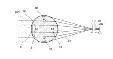
- FIG. 4 is a diagram showing spherical aberration when light is incident on the second outer surface from a direction perpendicular to the longitudinal direction of the multi-core fiber of FIG. 1 and is emitted from the first outer surface.
- 2 is a diagram showing spherical aberration when light is incident on a first outer surface from a direction perpendicular to the longitudinal direction of the multi-core fiber in FIG. 1 and is emitted from a second outer surface.
- 5 is a diagram showing a cross section perpendicular to the longitudinal direction of a multi-core fiber according to a second embodiment of the present invention.
- FIG. FIG. 11 is a diagram showing a cross section perpendicular to the longitudinal direction of a multi-core fiber according to a third embodiment of the present invention.
- FIG. 1 is a diagram showing a cross section perpendicular to the longitudinal direction of a multi-core fiber according to this embodiment.
- the multi-core fiber 1 of this embodiment includes a plurality of cores 10, a marker 15, a cladding 20 surrounding the outer circumferential surfaces of each of the cores 10 and the markers 15 without any gaps, an inner coating layer 31 coating the outer circumferential surface of the cladding 20, and an outer coating layer 32 coating the outer circumferential surface of the inner coating layer 31.
- an example having four cores 10 is shown.
- each core 10 is arranged on a circumference centered on a reference position 20R, which is approximately the center of the cladding 20. In this embodiment, each core 10 is arranged on the outermost side of the cladding 20. In the multicore fiber 1 of this embodiment, the distance between each core 10 is equal to each other, and each core 10 is arranged at a position that is approximately four-fold rotationally symmetric about the reference position 20R.
- the diameter of the core 10 is, for example, 4 ⁇ m or more and 14 ⁇ m or less.
- the markers 15 are arranged on the outside of the circumference on which each of the cores 10 is arranged.
- the refractive index of the markers 15 may be higher or lower than that of the cladding 20, provided that the refractive index is different from that of the cladding 20.
- each core 10 is higher than that of the cladding 20, and the relative refractive index difference of each core 10 with respect to the cladding 20 is, for example, 0.2% or more and 2.0% or less.
- a core 10 is made of silica glass doped with a dopant such as germanium that increases the refractive index
- the cladding 20 is made of silica glass with no dopant added.
- the core 10 may be made of silica glass with no dopant added
- the cladding 20 may be made of silica glass doped with a dopant such as fluorine that decreases the refractive index.
- the marker 15 is made of silica glass with a different refractive index from the cladding 20.
- the clad 20 has a non-circular outer shape, and has a first outer peripheral surface 21, which is a part in the circumferential direction, and a second outer peripheral surface 22, which is the other part in the circumferential direction.
- one of the parts of the outer peripheral surface of the clad 20 facing each core 10 is the first outer peripheral surface 21, and the other part of the outer peripheral surface of the clad 20 is the second outer peripheral surface 22.
- the part of the outer peripheral surface facing the core 10 is the part of the outer peripheral surface closest to the core 10. Therefore, the distance between the core 10 facing the first outer peripheral surface 21 and the first outer peripheral surface 21 is smaller than the distance between the core 10 and the second outer peripheral surface 22.
- the second outer peripheral surface 22 overlaps with a part of a predetermined circumference 20C centered on the reference position 20R of the clad 20.
- the circumference 20C shown by the dashed line and the second outer peripheral surface 22 are drawn slightly shifted.
- the first outer peripheral surface 21 bulges outward from the cladding 20 with a larger radius of curvature than the second outer peripheral surface 22 and is connected to the second outer peripheral surface 22. Therefore, the first outer peripheral surface 21 is located inside the circumference 20C.
- the length of the straight line connecting both ends of the first outer peripheral surface 21 is equal to or greater than the diameter of the core 10 that faces the first outer peripheral surface 21. Also, in this embodiment, when the first outer peripheral surface 21 is viewed along a direction perpendicular to the longitudinal direction of the multicore fiber 1, the core 10 that faces the first outer peripheral surface 21 completely overlaps the first outer peripheral surface 21.
- the first outer peripheral surface 21 is formed in only one location, so the outer peripheral surface of the cladding 20 has a rotationally asymmetric shape.
- the radius of curvature of the first outer peripheral surface 21 is preferably 1.5 to 20 times the radius of curvature of the second outer peripheral surface 22. In this way, by making the radius of curvature of the first outer peripheral surface 1.5 times or more the radius of curvature of the second outer peripheral surface, the outer peripheral surface of the cladding can become even closer to a flat surface. Therefore, rough alignment based on the outer peripheral surface of such cladding 20 can be performed even more easily. In addition, by making the radius of curvature of the first outer peripheral surface 20 times or less the radius of curvature of the second outer peripheral surface, spherical aberration can be suppressed when performing side view alignment.
- the inner coating layer 31 and the outer coating layer 32 are each made of a resin such as an ultraviolet-curable resin, and the inner coating layer 31 and the outer coating layer 32 are made of different resins.
- the multi-core fiber 1 of this embodiment by transmitting light through the multi-core fiber 1 of this embodiment as described above, it is possible to reduce the spherical aberration of a multi-core fiber having a circular cladding with a radius of curvature of the second outer peripheral surface, which is smaller than the spherical aberration of light when light is incident on the circular outer peripheral surface with a radius of curvature of the second outer peripheral surface from a direction perpendicular to the longitudinal direction of the circular cladding and the light is emitted from the circular outer peripheral surface, compared to when light is transmitted through the multi-core fiber. Since the spherical aberration of light is thus small, the multi-core fiber 1 can be aligned in the rotational direction with greater accuracy.
- FIG. 2 also shows the magnitude aD1 of spherical aberration when light is transmitted through a multicore fiber having a so-called D-shaped cladding in which the portion corresponding to the first outer peripheral surface 21 of the cladding is flat.
- this plane is indicated by a dotted line.
- the multicore fiber can be understood as a flat lens, and the magnitude aD1 of spherical aberration is smaller than the magnitude a1 of spherical aberration when light is transmitted through the multicore fiber 1 of this embodiment as described above.
- FIG. 3 is a diagram showing spherical aberration when light is incident on the first outer peripheral surface 21 from a direction perpendicular to the longitudinal direction of the multicore fiber 1 and emitted from the second outer peripheral surface 22.
- the multicore fiber 1 can be understood as a biconvex lens similar to a plano-convex lens, and the light emitted from the second outer peripheral surface 22 has a spherical aberration of magnitude a2.
- a plano-convex lens is a lens in which the surface on which light enters is formed flat and the surface from which light exits is formed convex.
- the magnitude a2 of the spherical aberration is larger than the magnitude a1 of the spherical aberration.
- FIG. 3 also shows the magnitude a0 of the spherical aberration when the same light is transmitted through a multicore fiber having a circular cladding. In this case, the magnitude a2 of the spherical aberration tends to be larger than the magnitude a0 of the spherical aberration.
- Figure 3 also shows the magnitude aD2 of spherical aberration when light is transmitted through a multicore fiber having a so-called D-shaped cladding in which the portion corresponding to the first outer peripheral surface 21 of the cladding is flat.
- this plane is indicated by a dotted line.
- the multicore fiber can be understood as a plano-convex lens, and the magnitude aD2 of spherical aberration is larger than the magnitude a2 of spherical aberration when light is transmitted through the multicore fiber 1 of this embodiment as described above.
- the first outer peripheral surface 21 may have a constant radius of curvature that overlaps with a portion of the circumference of a virtual circle not shown, or it may not have a constant radius of curvature.
- the shape of the first outer peripheral surface 21 may be a portion of an ellipse or a portion of a perfect circle.
- the multi-core fiber 1 of this embodiment alignment can be easily performed.
- the shape of the outer peripheral surface of the clad 20 is non-circular, rough alignment can be performed based on the outer shape of the clad 20 before side-view alignment.
- the alignment position can be determined to be one when performing the above-mentioned rough alignment, making alignment easier.
- the first outer surface 21 is a portion of the outer surface of the clad 20 that faces the core 10 arranged on the outer periphery. Therefore, the distance between the core 10 facing the first outer surface 21 and the first outer surface 21 is smaller than the distance between the core 10 facing the second outer surface 22 and the second outer surface 22.
- the multicore fiber 1 of this embodiment differs from the multicore fiber 1 of the first embodiment in that each of the portions of the outer surface of the cladding 20 that face the core 10 is designated as a first outer surface 21, and the other portions of the outer surface of the cladding 20 are designated as a second outer surface 22.
- each of the portions of the outer surface of the cladding 20 that face the cores 10 is the first outer surface 21, so that unnecessary higher-order mode light propagating through each core 10 can be attenuated by the influence of the first outer surface 21, compared to a multicore fiber having a circular cladding that overlaps with the second outer surface 22.
- the multicore fiber 1 of this embodiment differs from the multicore fiber 1 of the first embodiment in that the multiple cores 10 are arranged in a straight line.
- the cores 10 located at both ends are cores arranged on the outer periphery of the clad 20.
- each of the portions of the outer periphery of the clad 20 facing the cores 10 located at both ends is designated as a first outer periphery 21, and the other portions of the outer periphery of the clad 20 are designated as a second outer periphery 22.
- the shape of the outer periphery of the clad 20 may be the same as the shape of the outer periphery of the clad 20 in the first embodiment.
- first outer periphery 21 only one of the portions of the outer periphery of the clad 20 facing the cores 10 located at both ends is designated as the first outer periphery 21, and the other portions of the outer periphery of the clad 20 are designated as the second outer periphery 22.
- the present invention has been described above using the above embodiment as an example, but the present invention is not limited to this.
- the first outer peripheral surface 21 may be provided on the outer peripheral surface of the cladding 20 other than the portion facing the core 10.
- the first outer peripheral surface 21 may be provided at some of the multiple locations on the outer peripheral surface of the clad 20 that face the core 10.
- the multicore fiber 1 of the first embodiment is an example of this form.
- the first outer peripheral surface 21 may be provided at two or three of the four locations on the outer peripheral surface of the clad 20 that face the core 10. That is, some of the locations on the outer peripheral surface that face the core 10 arranged on the outer periphery of the clad 20 may be the first outer peripheral surface 21, and some of the other locations may be the second outer peripheral surface.
- all of the cores 10 are positioned on a circumference centered on the reference position 20R, but other cores may be positioned inside the circumference.
- a core may be positioned on the reference position 20R.
- the length of the straight line connecting both ends of the first outer peripheral surface 21 is equal to or greater than the diameter of the core 10 facing the first outer peripheral surface 21.
- the length of the straight line connecting both ends of the first outer peripheral surface 21 may be smaller than the diameter of the core 10.
- the length of the straight line connecting both ends of the first outer peripheral surface 21 is equal to or greater than the diameter of the core 10, higher-order mode light not required for communication can be absorbed more efficiently.
- the core 10 facing the first outer peripheral surface 21 when the first outer peripheral surface 21 is viewed along a direction perpendicular to the longitudinal direction of the multicore fiber 1, the core 10 facing the first outer peripheral surface 21 completely overlaps the first outer peripheral surface 21.
- a part of the core 10 facing the first outer peripheral surface 21 may overlap the first outer peripheral surface 21, and another part may not overlap the first outer peripheral surface 21.
- the core 10 facing the first outer peripheral surface 21 when the core 10 facing the first outer peripheral surface 21 completely overlaps the first outer peripheral surface 21, light in a higher mode that is not required for communication can be absorbed more efficiently.
- the present invention provides a multicore fiber that can be easily aligned, and can be used in the field of optical communications and other devices that use multicore fibers.
Landscapes
- Physics & Mathematics (AREA)
- General Physics & Mathematics (AREA)
- Optics & Photonics (AREA)
- Optical Couplings Of Light Guides (AREA)
Abstract
This multicore fiber (1) comprises multiple cores (10) and a cladding (20), wherein an outer circumferential surface of the cladding (20) has a first outer circumferential surface (21) forming one circumferential portion thereof and a second outer circumferential surface (22) forming another circumferential portion thereof, and the first outer circumferential surface (21) bulges outward with a radius of curvature larger than that of the second outer circumferential surface (22).
Description
本発明は、マルチコアファイバに関する。
The present invention relates to a multicore fiber.
近年、光ファイバ通信システムの普及に伴い、光ファイバによって伝送される情報量が飛躍的に増大している。このような背景から、複数のコアの外周が1つのクラッドにより囲まれたマルチコアファイバが用いられている。マルチコアファイバは複数のコアのそれぞれを伝搬する光により複数の信号を伝送させることができるので、1つの光ファイバ当たりの伝送容量が増大される。
In recent years, with the spread of optical fiber communication systems, the amount of information transmitted by optical fibers has increased dramatically. Against this background, multicore fibers, in which the outer circumference of multiple cores is surrounded by a single cladding, are being used. Multicore fibers can transmit multiple signals using light propagating through each of the multiple cores, which increases the transmission capacity per optical fiber.
長距離の光信号伝送にマルチコアファイバが用いられる場合、他のマルチコアファイバを接続する場合がある。この場合、マルチコアファイバの接続部における光の損失を低減する観点から、マルチコアファイバの各コアの配置精度を高めることが望まれる。
When a multicore fiber is used for long-distance optical signal transmission, it may be connected to another multicore fiber. In this case, it is desirable to improve the placement accuracy of each core of the multicore fiber in order to reduce the loss of light at the connection part of the multicore fiber.
下記特許文献1には、良好な光学的結合を実現するためにクラッドの外形が非円形とされたマルチコアファイバが記載されている。特許文献1には、例えば、外周面の一部が平面状に形成された所謂D型の外形のクラッドを有するマルチコアファイバが記載されている。
The following Patent Document 1 describes a multicore fiber in which the cladding has a noncircular outer shape in order to achieve good optical coupling. For example, Patent Document 1 describes a multicore fiber having a cladding with a so-called D-shaped outer shape in which part of the outer circumferential surface is formed into a flat shape.
クラッドの外形がD型のマルチコアファイバを回転方向に調心する場合、調心をクラッドの側面から光を照射してコア等の位置を観察して行うサイドビュー調心により行う場合がある。しかし、クラッドの外形がD型のマルチコアファイバでサイドビュー調心を行う場合、球面収差が大きくサイドビュー調心を行い難い回転位置がある。このような回転位置としては、クラッドの外周面のうち平面状の部位から光を入射させる位置を挙げることができる。このため、調心が困難な場合がある。
When aligning a multi-core fiber with a D-shaped cladding in the rotational direction, the alignment may be performed by side-view alignment, in which light is irradiated from the side of the cladding to observe the positions of the cores, etc. However, when performing side-view alignment on a multi-core fiber with a D-shaped cladding, there are rotational positions where spherical aberration is large and side-view alignment is difficult. An example of such a rotational position is a position where light is incident from a flat portion of the outer circumferential surface of the cladding. For this reason, alignment may be difficult.
そこで、本発明は、容易に調心をし得るマルチコアファイバを提供することを目的とする。
The present invention aims to provide a multicore fiber that can be easily aligned.
上記課題を解決するための本発明の態様1は、複数のコアおよび前記コアを囲うクラッドを備え、前記クラッドの外周面は、周方向における一部である第1外周面と、周方向における他の一部である第2外周面とを有し、前記第1外周面の少なくとも一部は、前記第2外周面より大きな曲率半径で前記クラッドの外側に膨らむことを特徴とするマルチコアファイバである。
Aspect 1 of the present invention for solving the above problem is a multi-core fiber comprising a plurality of cores and a cladding surrounding the cores, the outer surface of the cladding having a first outer surface which is a portion in the circumferential direction and a second outer surface which is another portion in the circumferential direction, and at least a portion of the first outer surface bulges outward from the cladding with a larger radius of curvature than the second outer surface.
このようなマルチコアファイバに対してサイドビュー調心を行う際、第1外周面側から光を入射する場合であっても、上記D型のクラッドの外周面のうち平面状の部位から光を入射させる場合と比べて、球面収差を抑えることができる。従って、本発明のマルチコアファイバによれば、容易に調心をし得る。
When performing side-view alignment on such a multicore fiber, even if light is incident from the first outer peripheral surface side, spherical aberration can be suppressed compared to when light is incident from a flat portion of the outer peripheral surface of the D-shaped cladding. Therefore, the multicore fiber of the present invention can be easily aligned.
また、本発明の態様2は、前記クラッドの外周側に複数の前記コアが配置され、複数の前記コアと対向する前記外周面のそれぞれの部位のうち少なくとも1つは、前記第1外周面であることを特徴とする態様1のマルチコアファイバである。
Aspect 2 of the present invention is a multicore fiber according to aspect 1, characterized in that a plurality of the cores are arranged on the outer circumferential side of the cladding, and at least one of the portions of the outer circumferential surface facing the plurality of the cores is the first outer circumferential surface.
コアと対向する外周面の部位とは、当該コアに最も近い外周面の部位である。従って、外周側に配置されるコアと当該コアと対向する第1外周面との距離は、外周側に配置されるコアと対向する外周面の部位が第2外周面である場合における当該コアと第2外周面との距離よりも小さい。従って、第1外周面に対向するコアを伝搬する不要な高次モードの光を第1外周面の影響により減衰させ得る。不要な高次モードの光は、例えば、通信に用いられない光である。
The portion of the outer circumferential surface facing the core is the portion of the outer circumferential surface closest to the core. Therefore, the distance between the core arranged on the outer circumferential side and the first outer circumferential surface facing the core is smaller than the distance between the core and the second outer circumferential surface when the portion of the outer circumferential surface facing the core arranged on the outer circumferential side is the second outer circumferential surface. Therefore, unnecessary higher-order mode light propagating through the core facing the first outer circumferential surface can be attenuated by the influence of the first outer circumferential surface. Unnecessary higher-order mode light is, for example, light not used for communication.
また、本発明の態様3は、前記部位のそれぞれが前記第1外周面であることを特徴とする態様2のマルチコアファイバである。
Aspect 3 of the present invention is the multi-core fiber of aspect 2, characterized in that each of the portions is the first outer circumferential surface.
この場合、外周側に配置されるそれぞれのコアを伝搬する不要な高次モードの光を第1外周面の影響により減衰させ得る。
In this case, the influence of the first outer peripheral surface can attenuate unnecessary higher-order mode light propagating through each of the cores arranged on the outer peripheral side.
また、本発明の態様4は、前記クラッドの前記外周面が非回転対称形状であることを特徴とする態様1から3のいずれかのマルチコアファイバである。
Aspect 4 of the present invention is a multicore fiber according to any one of aspects 1 to 3, characterized in that the outer peripheral surface of the cladding has a non-rotationally symmetric shape.
この場合、クラッドの外形によりクラッドの回転方向が特定の方向となるように、マルチコアファイバの粗調心を行うことができ得る。
In this case, it may be possible to roughly align the multicore fiber so that the cladding rotates in a specific direction depending on the cladding's outer shape.
また、本発明の態様5は、前記第1外周面の曲率半径は前記第2外周面の曲率半径の1.5倍以上、20倍以下であることを特徴とする態様1から4のいずれかのマルチコアファイバである。
Aspect 5 of the present invention is a multicore fiber according to any one of aspects 1 to 4, characterized in that the radius of curvature of the first outer peripheral surface is 1.5 times or more and 20 times or less than the radius of curvature of the second outer peripheral surface.
第1外周面の曲率半径と第2外周面の曲率半径との比がこのような関係であることで、クラッドの外周面に基づいた粗調心が一層容易に行うことができ、かつサイドビュー調心を行う際の球面収差を抑えることができる。
By having this ratio between the radius of curvature of the first outer peripheral surface and the radius of curvature of the second outer peripheral surface, rough alignment based on the outer peripheral surface of the cladding can be performed more easily, and spherical aberration can be suppressed when performing side-view alignment.
以上のように、本発明によれば、容易に調心をし得るマルチコアファイバが提供される。
As described above, the present invention provides a multicore fiber that can be easily aligned.
以下、本発明に係るマルチコアファイバの好適な実施形態について図面を参照しながら詳細に説明する。以下に例示する実施形態は、本発明の理解を容易にするためのものであり、本発明を限定して解釈するためのものではない。本発明は、請求項の範囲内において、その趣旨を逸脱することなく、実施形態から変更、改良することができる。なお、理解の容易のため、それぞれの図のスケールと、以下の説明に記載のスケールとが異なる場合がある。
Below, preferred embodiments of the multicore fiber according to the present invention will be described in detail with reference to the drawings. The embodiments exemplified below are intended to facilitate understanding of the present invention and are not intended to limit the interpretation of the present invention. The present invention can be modified and improved from the embodiments within the scope of the claims without departing from the spirit of the invention. Note that for ease of understanding, the scale of each figure may differ from the scale described in the following description.
(第1実施形態)
図1は、本実施形態に係るマルチコアファイバの長手方向に垂直な断面を示す図である。本実施形態のマルチコアファイバ1は、複数のコア10、マーカ15、それぞれのコア10及びマーカ15の外周面を隙間なく囲むクラッド20、クラッド20の外周面を被覆する内側被覆層31、内側被覆層31の外周面を被覆する外側被覆層32を備える。図1の例では、コア10が4つの例が示されている。 First Embodiment
Fig. 1 is a diagram showing a cross section perpendicular to the longitudinal direction of a multi-core fiber according to this embodiment. Themulti-core fiber 1 of this embodiment includes a plurality of cores 10, a marker 15, a cladding 20 surrounding the outer circumferential surfaces of each of the cores 10 and the markers 15 without any gaps, an inner coating layer 31 coating the outer circumferential surface of the cladding 20, and an outer coating layer 32 coating the outer circumferential surface of the inner coating layer 31. In the example of Fig. 1, an example having four cores 10 is shown.
図1は、本実施形態に係るマルチコアファイバの長手方向に垂直な断面を示す図である。本実施形態のマルチコアファイバ1は、複数のコア10、マーカ15、それぞれのコア10及びマーカ15の外周面を隙間なく囲むクラッド20、クラッド20の外周面を被覆する内側被覆層31、内側被覆層31の外周面を被覆する外側被覆層32を備える。図1の例では、コア10が4つの例が示されている。 First Embodiment
Fig. 1 is a diagram showing a cross section perpendicular to the longitudinal direction of a multi-core fiber according to this embodiment. The
本実施形態のマルチコアファイバ1では、それぞれのコア10は、クラッド20の概ね中心である基準位置20Rを中心とする円周上に配置されている。本実施形態では、それぞれのコア10がクラッド20の最外周側に配置されている。本実施形態のマルチコアファイバ1では、それぞれのコア10間の距離は互いに等しく、それぞれのコア10は基準位置20Rを中心として概ね4回回転対称となる位置に配置されている。コア10の直径は、例えば4μm以上14μm以下とされる。
In the multicore fiber 1 of this embodiment, each core 10 is arranged on a circumference centered on a reference position 20R, which is approximately the center of the cladding 20. In this embodiment, each core 10 is arranged on the outermost side of the cladding 20. In the multicore fiber 1 of this embodiment, the distance between each core 10 is equal to each other, and each core 10 is arranged at a position that is approximately four-fold rotationally symmetric about the reference position 20R. The diameter of the core 10 is, for example, 4 μm or more and 14 μm or less.
マーカ15は、それぞれのコア10が配置される円周の外側に配置される。マーカ15の屈折率は、クラッド20と異なる屈折率であれば、クラッド20よりも高くても低くてもよい。
The markers 15 are arranged on the outside of the circumference on which each of the cores 10 is arranged. The refractive index of the markers 15 may be higher or lower than that of the cladding 20, provided that the refractive index is different from that of the cladding 20.
それぞれのコア10の屈折率はクラッド20の屈折率よりも高く、それぞれのコア10のクラッド20に対する比屈折率差は、例えば0.2%以上2.0%以下とされる。このようなコア10は、例えば、ゲルマニウム等の屈折率が高くなるドーパントが添加されたシリカガラスから成り、クラッド20は、例えば、ドーパントが添加されていないシリカガラスから成る。また、コア10が何らドーパントが添加されていないシリカガラスから成り、クラッド20がフッ素等の屈折率が低くなるドーパントが添加されたシリカガラスから成る構成とされてもよい。マーカ15は、クラッド20とは屈折率が異なるシリカガラスによって構成される。
The refractive index of each core 10 is higher than that of the cladding 20, and the relative refractive index difference of each core 10 with respect to the cladding 20 is, for example, 0.2% or more and 2.0% or less. Such a core 10 is made of silica glass doped with a dopant such as germanium that increases the refractive index, and the cladding 20 is made of silica glass with no dopant added. Alternatively, the core 10 may be made of silica glass with no dopant added, and the cladding 20 may be made of silica glass doped with a dopant such as fluorine that decreases the refractive index. The marker 15 is made of silica glass with a different refractive index from the cladding 20.
クラッド20は、非円形の外形であり、周方向における一部である第1外周面21と、周方向における他の一部である第2外周面22とを有する。本実施形態では、それぞれのコア10と対向するクラッド20の外周面の部位のうち1つの部位が第1外周面21とされ、クラッド20の外周面の他の部位は第2外周面22とされる。コア10と対向する外周面の部位とは、当該コア10に最も近い外周面の部位である。従って、第1外周面21と対向するコア10と第1外周面21との距離は、当該コア10と第2外周面22との距離よりも小さい。第2外周面22は、クラッド20の基準位置20Rを中心とする所定の円周20Cの一部と重なっている。なお、図面の見やすさの観点から、破線で示される円周20Cと第2外周面22とは僅かにずらされて記載されている。第1外周面21は、第2外周面22より大きな曲率半径でクラッド20の外側に膨らみ第2外周面22と接続されている。このため、第1外周面21は、上記円周20Cの内側に位置する。
The clad 20 has a non-circular outer shape, and has a first outer peripheral surface 21, which is a part in the circumferential direction, and a second outer peripheral surface 22, which is the other part in the circumferential direction. In this embodiment, one of the parts of the outer peripheral surface of the clad 20 facing each core 10 is the first outer peripheral surface 21, and the other part of the outer peripheral surface of the clad 20 is the second outer peripheral surface 22. The part of the outer peripheral surface facing the core 10 is the part of the outer peripheral surface closest to the core 10. Therefore, the distance between the core 10 facing the first outer peripheral surface 21 and the first outer peripheral surface 21 is smaller than the distance between the core 10 and the second outer peripheral surface 22. The second outer peripheral surface 22 overlaps with a part of a predetermined circumference 20C centered on the reference position 20R of the clad 20. In addition, from the viewpoint of ease of viewing the drawing, the circumference 20C shown by the dashed line and the second outer peripheral surface 22 are drawn slightly shifted. The first outer peripheral surface 21 bulges outward from the cladding 20 with a larger radius of curvature than the second outer peripheral surface 22 and is connected to the second outer peripheral surface 22. Therefore, the first outer peripheral surface 21 is located inside the circumference 20C.
実施形態では、第1外周面21の両端を結ぶ直線の長さが、第1外周面21と対向するコア10の直径以上である。また、本実施形態では、マルチコアファイバ1の長手方向に垂直な方向に沿って、第1外周面21を見る場合に、第1外周面21と対向するコア10は、第1外周面21に完全に重なる。
In this embodiment, the length of the straight line connecting both ends of the first outer peripheral surface 21 is equal to or greater than the diameter of the core 10 that faces the first outer peripheral surface 21. Also, in this embodiment, when the first outer peripheral surface 21 is viewed along a direction perpendicular to the longitudinal direction of the multicore fiber 1, the core 10 that faces the first outer peripheral surface 21 completely overlaps the first outer peripheral surface 21.
このように本実施形態のクラッド20は、一カ所にのみ第1外周面21が形成されているため、クラッド20の外周面は、非回転対称形状である。
In this way, in the cladding 20 of this embodiment, the first outer peripheral surface 21 is formed in only one location, so the outer peripheral surface of the cladding 20 has a rotationally asymmetric shape.
第1外周面21の曲率半径は第2外周面22の曲率半径の1.5倍以上、20倍以下であることが好ましい。このように、第1外周面の曲率半径が第2外周面の曲率半径の1.5倍以上であることで、クラッドの外周面が一層平面状に近づき得る。したがって、このようなクラッド20の外周面に基づいた粗調心が一層容易に行うことができ得る。また、第1外周面の曲率半径が第2外周面の曲率半径の20倍以下であることで、サイドビュー調心を行う際の球面収差を抑えることができる。
The radius of curvature of the first outer peripheral surface 21 is preferably 1.5 to 20 times the radius of curvature of the second outer peripheral surface 22. In this way, by making the radius of curvature of the first outer peripheral surface 1.5 times or more the radius of curvature of the second outer peripheral surface, the outer peripheral surface of the cladding can become even closer to a flat surface. Therefore, rough alignment based on the outer peripheral surface of such cladding 20 can be performed even more easily. In addition, by making the radius of curvature of the first outer peripheral surface 20 times or less the radius of curvature of the second outer peripheral surface, spherical aberration can be suppressed when performing side view alignment.
内側被覆層31及び外側被覆層32はそれぞれ紫外線硬化性樹脂等の樹脂から成り、内側被覆層31及び外側被覆層32は互いに異なる樹脂から成る。
The inner coating layer 31 and the outer coating layer 32 are each made of a resin such as an ultraviolet-curable resin, and the inner coating layer 31 and the outer coating layer 32 are made of different resins.
このような形状のクラッド20を有するマルチコアファイバ1を製造するには、例えば、マルチコアファイバ1の母材のうちクラッド20となるクラッドロッドの外周面の一部を切削する。このようなクラッドロッドを有する母材を線引きしてマルチコアファイバ1とすることで、クラッドロッドの外周面うち切削された部分が第1外周面21となり、他の部分が第2外周面22となる。
To manufacture a multicore fiber 1 having a clad 20 of this shape, for example, a part of the outer surface of the clad rod that will become the clad 20 in the base material of the multicore fiber 1 is cut. By drawing a base material having such a clad rod to form the multicore fiber 1, the cut part of the outer surface of the clad rod becomes the first outer surface 21, and the other part becomes the second outer surface 22.
図2は、マルチコアファイバ1の長手方向に垂直な方向から第2外周面22に光を入射させて、第1外周面21から光を出射させる場合における球面収差を示す図である。なお、このようにマルチコアファイバ1に対して光を透過させる場合、内側被覆層31及び外側被覆層32は、剥離されている。図2の場合、第1外周面21が光の出射側に位置するため、マルチコアファイバ1を平面レンズに近い両凸レンズと理解することができ、第1外周面21から出射する光は、大きさa1の球面収差を有する。なお、平面レンズとは、光の入射する面が凸状に形成され、光の出射する面が平面状に形成されたレンズであり、両凸レンズとは、光の入射する面及び出射する面が共に凸状に形成されたレンズである。また、図2には、円形のクラッドを有するマルチコアファイバに対して、同様の光を透過させた場合の球面収差の大きさa0が示されている。円形のクラッドを有するマルチコアファイバを両凸レンズと理解することができる。このように、本実施形態のマルチコアファイバ1に対して上記のように光を透過させることで、円形クラッドの長手方向に垂直な方向から第2外周面の曲率半径を半径とする円形の外周面に光を入射させて、前記円形の外周面から当該光を出射させる場合の当該光の球面収差よりも小さい第2外周面の曲率半径を半径とする円形のクラッドを有するマルチコアファイバに対して、光を透過させる場合よりも、球面収差を小さくすることができる。このように光の球面収差が小さいことで、より精度よくマルチコアファイバ1の回転方向の調心を行うことができる。
2 is a diagram showing spherical aberration when light is incident on the second outer peripheral surface 22 from a direction perpendicular to the longitudinal direction of the multi-core fiber 1 and emitted from the first outer peripheral surface 21. When light is transmitted through the multi-core fiber 1 in this manner, the inner coating layer 31 and the outer coating layer 32 are peeled off. In the case of FIG. 2, since the first outer peripheral surface 21 is located on the light emission side, the multi-core fiber 1 can be understood as a biconvex lens close to a flat lens, and the light emitted from the first outer peripheral surface 21 has a spherical aberration of magnitude a1. Note that a flat lens is a lens in which the light incidence surface is formed convexly and the light emission surface is formed flatly, and a biconvex lens is a lens in which both the light incidence surface and the light emission surface are formed convexly. FIG. 2 also shows the magnitude a0 of spherical aberration when the same light is transmitted through a multi-core fiber having a circular cladding. A multi-core fiber having a circular cladding can be understood as a biconvex lens. In this way, by transmitting light through the multi-core fiber 1 of this embodiment as described above, it is possible to reduce the spherical aberration of a multi-core fiber having a circular cladding with a radius of curvature of the second outer peripheral surface, which is smaller than the spherical aberration of light when light is incident on the circular outer peripheral surface with a radius of curvature of the second outer peripheral surface from a direction perpendicular to the longitudinal direction of the circular cladding and the light is emitted from the circular outer peripheral surface, compared to when light is transmitted through the multi-core fiber. Since the spherical aberration of light is thus small, the multi-core fiber 1 can be aligned in the rotational direction with greater accuracy.
また、図2には、クラッドの第1外周面21に相当する部位が平面状である所謂D型のクラッドを有するマルチコアファイバに対して、同様に光を透過させた場合の球面収差の大きさaD1が示されている。図2において、この平面は、点線で示されている。この場合、マルチコアファイバを平面レンズと理解することができ、球面収差の大きさaD1は、本実施形態のマルチコアファイバ1に対して上記のように光を透過させる場合の球面収差の大きさa1よりも小さい。
FIG. 2 also shows the magnitude aD1 of spherical aberration when light is transmitted through a multicore fiber having a so-called D-shaped cladding in which the portion corresponding to the first outer peripheral surface 21 of the cladding is flat. In FIG. 2, this plane is indicated by a dotted line. In this case, the multicore fiber can be understood as a flat lens, and the magnitude aD1 of spherical aberration is smaller than the magnitude a1 of spherical aberration when light is transmitted through the multicore fiber 1 of this embodiment as described above.
図3は、マルチコアファイバ1の長手方向に垂直な方向から第1外周面21に光を入射させて、第2外周面22から光を出射させる場合における球面収差を示す図である。図3に示すように、この場合、マルチコアファイバ1を平凸レンズに近い両凸レンズと理解することができ、第2外周面22から出射する光は、大きさa2の球面収差を有する。なお、平凸レンズとは、光の入射する面が平面状に形成され、光の出射する面が凸状に形成されたレンズである。球面収差の大きさa2は、上記球面収差の大きさa1よりも大きい。また、図3には、円形のクラッドを有するマルチコアファイバに対して、同様の光を透過させた場合の球面収差の大きさa0が示されている。この場合、球面収差の大きさa2は、球面収差の大きさa0よりも大きい傾向にある。
FIG. 3 is a diagram showing spherical aberration when light is incident on the first outer peripheral surface 21 from a direction perpendicular to the longitudinal direction of the multicore fiber 1 and emitted from the second outer peripheral surface 22. As shown in FIG. 3, in this case, the multicore fiber 1 can be understood as a biconvex lens similar to a plano-convex lens, and the light emitted from the second outer peripheral surface 22 has a spherical aberration of magnitude a2. Note that a plano-convex lens is a lens in which the surface on which light enters is formed flat and the surface from which light exits is formed convex. The magnitude a2 of the spherical aberration is larger than the magnitude a1 of the spherical aberration. FIG. 3 also shows the magnitude a0 of the spherical aberration when the same light is transmitted through a multicore fiber having a circular cladding. In this case, the magnitude a2 of the spherical aberration tends to be larger than the magnitude a0 of the spherical aberration.
また、図3には、クラッドの第1外周面21に相当する部位が平面状である所謂D型のクラッドを有するマルチコアファイバに対して、同様に光を透過させた場合の球面収差の大きさaD2が示されている。図3において、この平面は、点線で示されている。この場合、マルチコアファイバを平凸レンズと理解することができ、球面収差の大きさaD2は、本実施形態のマルチコアファイバ1に対して上記のように光を透過させる場合の球面収差の大きさa2よりも大きい。
Figure 3 also shows the magnitude aD2 of spherical aberration when light is transmitted through a multicore fiber having a so-called D-shaped cladding in which the portion corresponding to the first outer peripheral surface 21 of the cladding is flat. In Figure 3, this plane is indicated by a dotted line. In this case, the multicore fiber can be understood as a plano-convex lens, and the magnitude aD2 of spherical aberration is larger than the magnitude a2 of spherical aberration when light is transmitted through the multicore fiber 1 of this embodiment as described above.
図2、図3の説明より、本実施形態のマルチコアファイバ1に対して、長手方向に垂直な方向から光を透過させ、マルチコアファイバ1を回転させる場合、D型のクラッドを有するマルチコアファイバよりも球面収差の変化量を抑制することができる。
As can be seen from the explanations of Figures 2 and 3, when light is transmitted through the multi-core fiber 1 of this embodiment in a direction perpendicular to the longitudinal direction and the multi-core fiber 1 is rotated, the amount of change in spherical aberration can be suppressed more than in a multi-core fiber having a D-shaped cladding.
なお、第1外周面21の曲率半径が第2外周面22の曲率半径よりも大きい限りにおいて、第1外周面21が不図示の仮想円の円周の一部と重なる一定の曲率半径であっても良く、一定の曲率半径でなくても良い。たとえば、第1外周面21の曲率半径が第2外周面22の曲率半径よりも大きければ、第1外周面21の形状は楕円の一部であっても良く、正円の一部であっても良い。
In addition, as long as the radius of curvature of the first outer peripheral surface 21 is greater than the radius of curvature of the second outer peripheral surface 22, the first outer peripheral surface 21 may have a constant radius of curvature that overlaps with a portion of the circumference of a virtual circle not shown, or it may not have a constant radius of curvature. For example, if the radius of curvature of the first outer peripheral surface 21 is greater than the radius of curvature of the second outer peripheral surface 22, the shape of the first outer peripheral surface 21 may be a portion of an ellipse or a portion of a perfect circle.
以上説明したように、本実施形態のマルチコアファイバ1は、クラッド20の外周面は、周方向における一部である第1外周面21と、周方向における他の一部である第2外周面22とを有し、第1外周面21は、第2外周面22より大きな曲率半径でクラッド20の外側に膨らむ。従って、サイドビュー調心を行う際、第1外周面21側から光を入射する場合であっても、D型のクラッドの外周面のうち平面状の部位から光を入射させる場合と比べて、球面収差を抑えることができ、マルチコアファイバ1を回転させる場合にD型のクラッドを有するマルチコアファイバよりも球面収差の変化量を抑制することができる。従って、本実施形態のマルチコアファイバ1によれば、容易に調心をし得る。また、クラッド20の外周面の形状が非円形であるため、サイドビュー調心を行う前に、クラッド20の外形に基づいて粗調心を行うことができる。
As described above, in the multi-core fiber 1 of this embodiment, the outer peripheral surface of the clad 20 has a first outer peripheral surface 21 which is a part in the circumferential direction and a second outer peripheral surface 22 which is the other part in the circumferential direction, and the first outer peripheral surface 21 bulges outward from the clad 20 with a larger radius of curvature than the second outer peripheral surface 22. Therefore, even when light is incident from the first outer peripheral surface 21 side during side-view alignment, spherical aberration can be suppressed compared to when light is incident from a planar portion of the outer peripheral surface of the D-shaped clad, and when the multi-core fiber 1 is rotated, the amount of change in spherical aberration can be suppressed more than in a multi-core fiber having a D-shaped clad. Therefore, according to the multi-core fiber 1 of this embodiment, alignment can be easily performed. In addition, since the shape of the outer peripheral surface of the clad 20 is non-circular, rough alignment can be performed based on the outer shape of the clad 20 before side-view alignment.
また、本実施形態のマルチコアファイバ1のようにクラッド20の外周面が非回転対称形状であれば、上記粗調心を行う際に調心位置を一つに定めることができるので、調心をより容易に行うことができる。
In addition, if the outer peripheral surface of the cladding 20 has a rotationally asymmetric shape, as in the multicore fiber 1 of this embodiment, the alignment position can be determined to be one when performing the above-mentioned rough alignment, making alignment easier.
また、本実施形態のマルチコアファイバ1では、第1外周面21は、外周側に配置されるコア10と対向するクラッド20の外周面の部位である。従って、第1外周面21と対向するコア10と第1外周面21との距離は、第2外周面22と対向するコア10と第2外周面22との距離よりも小さい。ここで、コア10の外周面とクラッド20の外周面との距離が近いほど、コア10を伝搬する高次モードがクラッド20側に伝搬しやすくなる傾向にある。従って、第1外周面21と対向するコア10を伝搬する通信等に不要な高次モードの光を第1外周面21の影響により減衰させ得る。
In addition, in the multicore fiber 1 of this embodiment, the first outer surface 21 is a portion of the outer surface of the clad 20 that faces the core 10 arranged on the outer periphery. Therefore, the distance between the core 10 facing the first outer surface 21 and the first outer surface 21 is smaller than the distance between the core 10 facing the second outer surface 22 and the second outer surface 22. Here, the closer the distance between the outer surface of the core 10 and the outer surface of the clad 20, the more likely it is that higher-order modes propagating through the core 10 will propagate to the clad 20 side. Therefore, higher-order mode light that is unnecessary for communication, etc., that propagates through the core 10 facing the first outer surface 21 can be attenuated by the influence of the first outer surface 21.
(第2実施形態)
次に、本発明の第2実施形態について図4を参照して詳細に説明する。なお、第1実施形態と同一又は同等の構成要素については、特に説明する場合を除き、同一の参照符号を付して重複する説明は省略する。 Second Embodiment
Next, a second embodiment of the present invention will be described in detail with reference to Fig. 4. Note that components that are the same as or equivalent to those in the first embodiment will be given the same reference numerals and will not be described again unless otherwise specified.
図4に示すように、本実施形態のマルチコアファイバ1は、コア10と対向するクラッド20の外周面の部位のそれぞれが第1外周面21とされ、クラッド20の外周面の他の部位は第2外周面22とされる点において、第1実施形態のマルチコアファイバ1と異なる。
As shown in FIG. 4, the multicore fiber 1 of this embodiment differs from the multicore fiber 1 of the first embodiment in that each of the portions of the outer surface of the cladding 20 that face the core 10 is designated as a first outer surface 21, and the other portions of the outer surface of the cladding 20 are designated as a second outer surface 22.
本実施形態のマルチコアファイバ1では、コア10と対向するクラッド20の外周面の部位のそれぞれが第1外周面21とされるため、第2外周面22と重なる円形のクラッドを有するマルチコアファイバと比べて、それぞれのコア10を伝搬する不要な高次モードの光を第1外周面21の影響により減衰させ得る。
In the multicore fiber 1 of this embodiment, each of the portions of the outer surface of the cladding 20 that face the cores 10 is the first outer surface 21, so that unnecessary higher-order mode light propagating through each core 10 can be attenuated by the influence of the first outer surface 21, compared to a multicore fiber having a circular cladding that overlaps with the second outer surface 22.
(第3実施形態)
次に、本発明の第3実施形態について図5を参照して詳細に説明する。なお、第1実施形態と同一又は同等の構成要素については、特に説明する場合を除き、同一の参照符号を付して重複する説明は省略する。 Third Embodiment
Next, a third embodiment of the present invention will be described in detail with reference to Fig. 5. Note that components that are the same as or equivalent to those in the first embodiment will be given the same reference numerals and will not be described again unless otherwise specified.
図5に示すように、本実施形態のマルチコアファイバ1は、複数のコア10が直線状に配置されている点において、第1実施形態のマルチコアファイバ1と異なる。
As shown in FIG. 5, the multicore fiber 1 of this embodiment differs from the multicore fiber 1 of the first embodiment in that the multiple cores 10 are arranged in a straight line.
本実施形態では、両端に位置するコア10が、クラッド20の外周側に配置されるコアである。また、本実施形態では、両端に位置するコア10と対向するクラッド20の外周面の部位のそれぞれが第1外周面21とされ、クラッド20の外周面の他の部位は第2外周面22とされる。なお、クラッド20の外周面の形状は第1実施形態のクラッド20の外周面の形状と同様とされてもよい。この場合、両端に位置するコア10と対向するクラッド20の外周面のそれぞれの部位のうち、一方のみが第1外周面21とされ、クラッド20の外周面の他の部位は第2外周面22とされる。
In this embodiment, the cores 10 located at both ends are cores arranged on the outer periphery of the clad 20. Also, in this embodiment, each of the portions of the outer periphery of the clad 20 facing the cores 10 located at both ends is designated as a first outer periphery 21, and the other portions of the outer periphery of the clad 20 are designated as a second outer periphery 22. The shape of the outer periphery of the clad 20 may be the same as the shape of the outer periphery of the clad 20 in the first embodiment. In this case, only one of the portions of the outer periphery of the clad 20 facing the cores 10 located at both ends is designated as the first outer periphery 21, and the other portions of the outer periphery of the clad 20 are designated as the second outer periphery 22.
以上、本発明について、上記実施形態を例に説明したが、本発明はこれに限定されるものではない。例えば、第1外周面21は、クラッド20の外周面のうちコア10と対向する部位以外に設けられてもよい。
The present invention has been described above using the above embodiment as an example, but the present invention is not limited to this. For example, the first outer peripheral surface 21 may be provided on the outer peripheral surface of the cladding 20 other than the portion facing the core 10.
また、第1外周面21は、クラッド20の外周面におけるコア10と対向する複数の部位のうち一部の部位に設けられてもよい。第1実施形態のマルチコアファイバ1は、この形態の一例である。また、第1実施形態において、クラッド20の外周面におけるコア10と対向する4つの部位のうち二か所或いは三カ所に第1外周面21が設けられてもよい。すなわち、クラッド20の外周側に配置されるコア10と対向する外周面の部位のうち一部の部位が第1外周面21とされ、当該部位のうち他の一部の部位が第2外周面とされてもよい。
The first outer peripheral surface 21 may be provided at some of the multiple locations on the outer peripheral surface of the clad 20 that face the core 10. The multicore fiber 1 of the first embodiment is an example of this form. In the first embodiment, the first outer peripheral surface 21 may be provided at two or three of the four locations on the outer peripheral surface of the clad 20 that face the core 10. That is, some of the locations on the outer peripheral surface that face the core 10 arranged on the outer periphery of the clad 20 may be the first outer peripheral surface 21, and some of the other locations may be the second outer peripheral surface.
また、第1、第2実施形態では、全てのコア10が基準位置20Rを中心とする円周上に位置したが、当該円周の内側に他のコアが配置されてもよい。例えば、基準位置20R上にコアが配置されてもよい。
In the first and second embodiments, all of the cores 10 are positioned on a circumference centered on the reference position 20R, but other cores may be positioned inside the circumference. For example, a core may be positioned on the reference position 20R.
また、上記実施形態では、第1外周面21の両端を結ぶ直線の長さが、第1外周面21と対向するコア10の直径以上となる例で説明した。しかし、第1外周面21の両端を結ぶ直線の長さが、コア10の直径よりも小さくてもよい。ただし、上記実施形態のように、第1外周面21の両端を結ぶ直線の長さが、コア10の直径以上の方が、通信に不要な高次モードの光を効率よく吸収し得る。
In addition, in the above embodiment, an example has been described in which the length of the straight line connecting both ends of the first outer peripheral surface 21 is equal to or greater than the diameter of the core 10 facing the first outer peripheral surface 21. However, the length of the straight line connecting both ends of the first outer peripheral surface 21 may be smaller than the diameter of the core 10. However, as in the above embodiment, if the length of the straight line connecting both ends of the first outer peripheral surface 21 is equal to or greater than the diameter of the core 10, higher-order mode light not required for communication can be absorbed more efficiently.
また、上記実施形態では、マルチコアファイバ1の長手方向に垂直な方向に沿って、第1外周面21を見る場合に、第1外周面21と対向するコア10は、第1外周面21に完全に重なる。しかし、同様に見る場合に、第1外周面21と対向するコア10の一部が第1外周面21に重なり、他の一部が第1外周面21に重ならなくてもよい。ただし、第1外周面21と対向するコア10が第1外周面21に完全に重なる方が、通信に不要な高次モードの光を効率よく吸収し得る。
In addition, in the above embodiment, when the first outer peripheral surface 21 is viewed along a direction perpendicular to the longitudinal direction of the multicore fiber 1, the core 10 facing the first outer peripheral surface 21 completely overlaps the first outer peripheral surface 21. However, when viewed in the same manner, a part of the core 10 facing the first outer peripheral surface 21 may overlap the first outer peripheral surface 21, and another part may not overlap the first outer peripheral surface 21. However, when the core 10 facing the first outer peripheral surface 21 completely overlaps the first outer peripheral surface 21, light in a higher mode that is not required for communication can be absorbed more efficiently.
以上説明したように、本発明によれば、容易に調心をし得るマルチコアファイバが提供され、光通信の分野や、その他マルチコアファイバを利用したデバイスに利用することができる。
As described above, the present invention provides a multicore fiber that can be easily aligned, and can be used in the field of optical communications and other devices that use multicore fibers.
Claims (5)
- 複数のコアおよび前記コアを囲うクラッドを備え、
前記クラッドの外周面は、周方向における一部である第1外周面と、周方向における他の一部である第2外周面とを有し、
前記第1外周面は、前記第2外周面より大きな曲率半径で前記クラッドの外側に膨らむ
ことを特徴とするマルチコアファイバ。 A plurality of cores and a cladding surrounding the cores;
The outer peripheral surface of the clad has a first outer peripheral surface which is a part in the circumferential direction and a second outer peripheral surface which is another part in the circumferential direction,
The first outer peripheral surface bulges outward from the cladding with a larger radius of curvature than the second outer peripheral surface. - 前記複数のコアのうち前記クラッドの外周側に2以上の前記コアが配置され、
前記コアと対向する前記外周面の部位のうち少なくとも1つは、前記第1外周面である
ことを特徴とする請求項1に記載のマルチコアファイバ。 Among the plurality of cores, two or more of the cores are arranged on an outer circumferential side of the cladding,
The multi-core fiber according to claim 1 , wherein at least one of the portions of the outer circumferential surface facing the core is the first outer circumferential surface. - 前記部位のそれぞれが前記第1外周面である
ことを特徴とする請求項2に記載のマルチコアファイバ。 The multi-core fiber according to claim 2 , wherein each of the portions is the first outer circumferential surface. - 前記クラッドの前記外周面は、非回転対称形状である
ことを特徴とする請求項1から3のいずれか1項に記載のマルチコアファイバ。 The multicore fiber according to claim 1 , wherein the outer peripheral surface of the cladding has a rotationally asymmetric shape. - 前記第1外周面の曲率半径は前記第2外周面の曲率半径の1.5倍以上、20倍以下である
ことを特徴とする請求項1から4のいずれか1項に記載のマルチコアファイバ。 The multicore fiber according to any one of claims 1 to 4, wherein the radius of curvature of the first outer peripheral surface is 1.5 to 20 times the radius of curvature of the second outer peripheral surface.
Applications Claiming Priority (2)
| Application Number | Priority Date | Filing Date | Title |
|---|---|---|---|
| JP2023021006 | 2023-02-14 | ||
| JP2023-021006 | 2023-02-14 |
Publications (1)
| Publication Number | Publication Date |
|---|---|
| WO2024171835A1 true WO2024171835A1 (en) | 2024-08-22 |
Family
ID=92421809
Family Applications (1)
| Application Number | Title | Priority Date | Filing Date |
|---|---|---|---|
| PCT/JP2024/003354 WO2024171835A1 (en) | 2023-02-14 | 2024-02-01 | Multicore fiber |
Country Status (1)
| Country | Link |
|---|---|
| WO (1) | WO2024171835A1 (en) |
Citations (7)
| Publication number | Priority date | Publication date | Assignee | Title |
|---|---|---|---|---|
| US20120069861A1 (en) * | 2009-05-27 | 2012-03-22 | Wolfgang Neuberger | Precisely-Shaped Core Fibers and Method of Manufacture |
| JP2013160800A (en) * | 2012-02-01 | 2013-08-19 | Sumitomo Electric Ind Ltd | Multi-core optical fiber tape |
| JP2016075918A (en) * | 2015-11-13 | 2016-05-12 | 三菱電線工業株式会社 | Optical fiber and method for manufacturing the optical fiber |
| WO2016084465A1 (en) * | 2014-11-27 | 2016-06-02 | 古河電気工業株式会社 | Optical fiber, method for centering optical fiber and connection structure for same, tape core wire, and method for manufacturing same |
| JP2019172491A (en) * | 2018-03-28 | 2019-10-10 | 住友電気工業株式会社 | Method for manufacturing multicore optical fiber and multicore optical fiber |
| WO2020195739A1 (en) * | 2019-03-27 | 2020-10-01 | 古河電気工業株式会社 | Multicore fiber preform manufacturing method, multicore fiber preform, and multicore fiber |
| JP2020164363A (en) * | 2019-03-29 | 2020-10-08 | 住友電気工業株式会社 | Method of manufacturing multi-core optical fiber |
-
2024
- 2024-02-01 WO PCT/JP2024/003354 patent/WO2024171835A1/en unknown
Patent Citations (7)
| Publication number | Priority date | Publication date | Assignee | Title |
|---|---|---|---|---|
| US20120069861A1 (en) * | 2009-05-27 | 2012-03-22 | Wolfgang Neuberger | Precisely-Shaped Core Fibers and Method of Manufacture |
| JP2013160800A (en) * | 2012-02-01 | 2013-08-19 | Sumitomo Electric Ind Ltd | Multi-core optical fiber tape |
| WO2016084465A1 (en) * | 2014-11-27 | 2016-06-02 | 古河電気工業株式会社 | Optical fiber, method for centering optical fiber and connection structure for same, tape core wire, and method for manufacturing same |
| JP2016075918A (en) * | 2015-11-13 | 2016-05-12 | 三菱電線工業株式会社 | Optical fiber and method for manufacturing the optical fiber |
| JP2019172491A (en) * | 2018-03-28 | 2019-10-10 | 住友電気工業株式会社 | Method for manufacturing multicore optical fiber and multicore optical fiber |
| WO2020195739A1 (en) * | 2019-03-27 | 2020-10-01 | 古河電気工業株式会社 | Multicore fiber preform manufacturing method, multicore fiber preform, and multicore fiber |
| JP2020164363A (en) * | 2019-03-29 | 2020-10-08 | 住友電気工業株式会社 | Method of manufacturing multi-core optical fiber |
Similar Documents
| Publication | Publication Date | Title |
|---|---|---|
| US4252403A (en) | Coupler for a graded index fiber | |
| CN110161622B (en) | Multi-core optical fiber, optical cable, and optical connector | |
| JP5916525B2 (en) | Multi-core fiber | |
| JP5782502B2 (en) | Multi-core fiber and multi-core fiber connection method using the same | |
| WO2011024808A1 (en) | Multi-core fiber | |
| JP2023126651A (en) | multi-core optical fiber | |
| WO2022118985A1 (en) | Fiber connecting body, optical communication system, optical device, and method for manufacturing fiber connecting body | |
| JP5471776B2 (en) | Multi-core optical fiber | |
| US20220066091A1 (en) | Multi-core optical fiber and multi-core optical fiber cable | |
| CN111007590B (en) | Weakly coupled few-mode optical fiber for mode division multiplexing and corresponding optical transmission system | |
| WO2022176978A1 (en) | Optical input/output device | |
| JP2018124307A (en) | Optical connector and optical transmission system | |
| US9835812B2 (en) | Multi-optical fiber aggregate | |
| CN108873157B (en) | Low-magnetic-sensitivity polarization-maintaining photonic crystal fiber | |
| CN116368105A (en) | Multi-core optical fiber | |
| CN109073822B (en) | Lensed optical fiber and optical coupler | |
| US11604312B2 (en) | Multi-core optical fiber and multi-core optical fiber cable | |
| JP7227255B2 (en) | Bridge fiber, multi-core fiber unit, multi-core bridge fiber, and multi-core multi-core fiber unit | |
| US8111962B2 (en) | Optical fiber connection structure and single-mode fiber | |
| WO2024171835A1 (en) | Multicore fiber | |
| US20110176767A1 (en) | Optical fiber connection structure | |
| US20230185017A1 (en) | Multi-core optical fiber and multi-core optical fiber cable | |
| JP2022066064A (en) | Multi-core optical fiber and multi-core optical fiber cable | |
| US20240061204A1 (en) | Fan-in/fan-out device | |
| CN212749311U (en) | Compact type online four-port optical fiber wavelength division multiplexer with high coaxiality |