WO2024171675A1 - 温度管理装置 - Google Patents
温度管理装置 Download PDFInfo
- Publication number
- WO2024171675A1 WO2024171675A1 PCT/JP2024/000661 JP2024000661W WO2024171675A1 WO 2024171675 A1 WO2024171675 A1 WO 2024171675A1 JP 2024000661 W JP2024000661 W JP 2024000661W WO 2024171675 A1 WO2024171675 A1 WO 2024171675A1
- Authority
- WO
- WIPO (PCT)
- Prior art keywords
- temperature
- flow path
- lead
- fluid
- cooling water
- Prior art date
- Legal status (The legal status is an assumption and is not a legal conclusion. Google has not performed a legal analysis and makes no representation as to the accuracy of the status listed.)
- Ceased
Links
Images




Classifications
-
- F—MECHANICAL ENGINEERING; LIGHTING; HEATING; WEAPONS; BLASTING
- F01—MACHINES OR ENGINES IN GENERAL; ENGINE PLANTS IN GENERAL; STEAM ENGINES
- F01P—COOLING OF MACHINES OR ENGINES IN GENERAL; COOLING OF INTERNAL-COMBUSTION ENGINES
- F01P3/00—Liquid cooling
- F01P3/02—Arrangements for cooling cylinders or cylinder heads
-
- F—MECHANICAL ENGINEERING; LIGHTING; HEATING; WEAPONS; BLASTING
- F01—MACHINES OR ENGINES IN GENERAL; ENGINE PLANTS IN GENERAL; STEAM ENGINES
- F01P—COOLING OF MACHINES OR ENGINES IN GENERAL; COOLING OF INTERNAL-COMBUSTION ENGINES
- F01P7/00—Controlling of coolant flow
- F01P7/14—Controlling of coolant flow the coolant being liquid
- F01P7/16—Controlling of coolant flow the coolant being liquid by thermostatic control
- F01P7/164—Controlling of coolant flow the coolant being liquid by thermostatic control by varying pump speed
-
- F—MECHANICAL ENGINEERING; LIGHTING; HEATING; WEAPONS; BLASTING
- F01—MACHINES OR ENGINES IN GENERAL; ENGINE PLANTS IN GENERAL; STEAM ENGINES
- F01P—COOLING OF MACHINES OR ENGINES IN GENERAL; COOLING OF INTERNAL-COMBUSTION ENGINES
- F01P3/00—Liquid cooling
- F01P3/02—Arrangements for cooling cylinders or cylinder heads
- F01P2003/027—Cooling cylinders and cylinder heads in parallel
-
- F—MECHANICAL ENGINEERING; LIGHTING; HEATING; WEAPONS; BLASTING
- F01—MACHINES OR ENGINES IN GENERAL; ENGINE PLANTS IN GENERAL; STEAM ENGINES
- F01P—COOLING OF MACHINES OR ENGINES IN GENERAL; COOLING OF INTERNAL-COMBUSTION ENGINES
- F01P5/00—Pumping cooling-air or liquid coolants
- F01P5/10—Pumping liquid coolant; Arrangements of coolant pumps
- F01P2005/105—Using two or more pumps
Definitions
- This disclosure relates to a temperature management device.
- Patent Document 1 discloses a cooling control system that includes a radiator connected to the engine via a first circulation passage and dissipating heat from the cooling water (cooling liquid) flowing through the first circulation passage, and a heater core connected to the engine via a second circulation passage and dissipating heat from the cooling water flowing through the second circulation passage.
- the first circulation passage includes an outlet passage that connects a cooling water outlet provided in the upper part of the engine (cylinder head) to an inlet of the radiator, and an inlet passage that connects the outlet of the radiator to a cooling water inlet in the lower part of the engine (cylinder block).
- the second circulation passage includes an outlet passage that connects a cooling water outlet provided in the upper part of the engine (cylinder head) to an inlet of the heater core, and an inlet passage that connects the outlet of the heater core to an inlet passage of the first circulation passage.
- the temperatures of the cylinder block and the cylinder head are managed only by the cooling water that flows into the cooling water inlet, and the temperatures of the cylinder head and the cylinder block cannot be managed independently, and there is room for improvement in the temperature management of objects to be temperature-managed such as engines.
- This disclosure has been made in consideration of the above problems, and its purpose is to provide a temperature management device that can more precisely manage the temperature of an object to be temperature-managed.
- the temperature management device is characterized in that it is a temperature management device that manages the temperature of a temperature managed object having a first managed object and a second managed object by circulating a fluid, and is equipped with a first pump that transfers a fluid of a first temperature that is heated by the temperature managed object, a second pump that transfers a fluid of a second temperature that is lower than the first temperature, a first flow path that guides the fluid of the first temperature transferred by the first pump to the first managed object, a second flow path through which the fluid of the second temperature transferred by the second pump flows, and a switching flow path that is connected to the first flow path and the second flow path and switches the temperature of the fluid to be guided to the second managed object, and the switching flow path is used to switch the temperature of the fluid of the first temperature or a third temperature fluid that is a mixture of the fluid of the first temperature and the fluid of the second temperature.
- a first flow path that guides a fluid at a first temperature to a first managed object, and a switching flow path that guides the fluid to a second managed object are provided separately.
- the switching flow path allows the first temperature fluid, or a third temperature fluid that is a mixture of the first temperature fluid and the second temperature fluid, to flow, in other words, the temperature of the fluid flowing through the switching flow path can also be switched. This allows for more precise temperature management of the object to be temperature managed.
- FIG. 1 is a diagram showing an outline of a temperature management device according to an embodiment
- FIG. 2 is a diagram illustrating a configuration of a temperature management unit according to the embodiment.
- FIG. 2 is a diagram illustrating a configuration of a temperature management unit according to the embodiment.
- 4A and 4B are diagrams illustrating a configuration of a switching flow path and its vicinity according to the embodiment.
- 4A and 4B are diagrams illustrating a configuration of a switching flow path and its vicinity according to the embodiment.
- FIG. 2 is a diagram illustrating a cross section of a switching channel and its vicinity according to an embodiment.
- 5A and 5B are diagrams illustrating a configuration of a lead channel according to the embodiment.
- FIG. 2 is a diagram showing a temperature sensor unit according to the embodiment
- 5A and 5B are diagrams illustrating the configuration of a junction lead channel and a temperature sensor according to the embodiment.
- 13 is a diagram showing a configuration in the vicinity of a switching flow path according to another embodiment.
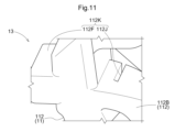
- FIG. FIG. 13 is an enlarged view showing a configuration in the vicinity of a switching flow path according to another embodiment.
- the temperature management device 100 is mounted on a vehicle V such as an automobile.
- the temperature management device 100 manages the temperature of an engine E (an example of a subject to temperature management) as an internal combustion engine mounted on the vehicle V.
- the temperature management device 100 operates in two operating modes. Specifically, the temperature management device 100 operates in a first mode in which it operates to raise the temperature (warm up) of the engine E, or in a second mode in which it operates to bring the temperature of the engine E to a target temperature.
- the first mode will be referred to as the “warm up mode”
- the second mode will be referred to as the "temperature control mode.”
- the temperature management device 100 has a temperature management unit 10 that manages the temperature of the engine E, and a control unit 20 that controls the operation of the temperature management unit 10.
- FIGS. 2 and 3 are diagrams showing the configuration of the temperature management unit 10.
- Fig. 2 shows the temperature management unit 10 in a warm-up mode
- Fig. 3 shows the temperature management unit 10 in a temperature adjustment mode.
- the temperature management unit 10 manages the temperature of the engine E by circulating coolant W (an example of a fluid).
- the coolant W is a cooling fluid such as long-life coolant (LLC).
- the temperature management unit 10 has a fluid flow path 1 through which coolant W flows to manage the temperature of the engine E, a radiator 2 that cools (lowers the temperature of) the coolant W, a pump 3 that circulates the coolant W in the fluid flow path 1, and a temperature sensor 4 (an example of a sensor) that acquires (measures) the temperature of the coolant W.
- the radiator 2, pump 3, temperature sensor 4, and engine E are connected via the fluid flow path 1 through which the coolant W flows.
- the downstream side of the flow direction of the coolant W flowing through the fluid flow path 1 will be referred to simply as the "downstream side", and the upstream side will be referred to simply as the "upstream side".
- the engine E includes a cylinder block EB (an example of a first managed object) and a cylinder head EH (an example of a second managed object).
- the cylinder block EB is provided with a piston that generates power using thermal energy generated by the combustion of fuel.
- the cylinder head EH is provided with an intake port for intake and an exhaust port for exhaust.
- the cylinder head EH and the cylinder block EB form a combustion chamber.
- the engine E is also provided with an engine inlet E1 through which the cooling water W flows from the fluid flow path 1 into the engine E, and an engine outlet E2 through which the cooling water W flows from the engine E into the fluid flow path 1.
- the engine inlet E1 includes a first engine inlet E11 connected to the cylinder block EB and a second engine inlet E12 connected to the cylinder head EH.
- the cooling water W that flows into the cylinder block EB through the first engine inlet E11 flows from the cylinder block EB to the cylinder head EH through the engine internal flow passage EL formed inside the engine E.
- the cooling water W that flows into the cylinder head EH flows out into the fluid flow passage 1 through the engine outlet E2.
- the cooling water W that flows into the cylinder head EH through the second engine inlet E12 flows out into the fluid flow passage 1 through the engine outlet E2.
- the radiator 2 is a heat exchanger that cools the coolant W by exchanging heat between the coolant W and air, etc.
- the pump 3 circulates the cooling water W in the fluid flow path 1 by transporting the cooling water W.
- the pump 3 is an electric water pump, and includes an electric motor (not shown) and an impeller (not shown) that is driven by power from the electric motor.
- the pressure (discharge rate) of the pump 3 changes when the control unit 20 described with reference to FIG. 1 controls the operation of the electric motor (the rotational speed of the impeller).
- the pump 3 includes a first pump 31 that transfers coolant W at a first temperature that has been heated by the engine E, and a second pump 32 that transfers coolant W at a second temperature that has been cooled by the radiator 2.
- the first temperature is, for example, 90 degrees to 95 degrees
- the second temperature is, for example, 0 degrees to 40 degrees (same as the outside air). Since the second temperature is lower than the first temperature, hereinafter the first temperature may be referred to as "high temperature” and the second temperature may be referred to as "low temperature.”
- the temperature sensor 4 measures the temperature of the cooling water W and outputs information indicating the measured temperature.
- the control unit 20 controls the operation (pressure) of the pump 3 based on the information indicating the temperature of the cooling water W output from the temperature sensor 4 and information indicating the amount of heat generated by the engine E.
- the control unit 20 obtains the amount of heat generated by the engine E based on information indicating the rotation speed of the engine E, the load factor of the engine E, etc.
- the fluid flow path 1 includes a high-temperature flow path 11 (an example of a first flow path) through which coolant W at a first temperature (high temperature) flows, a low-temperature flow path 12 (an example of a second flow path) through which coolant W at a second temperature (low temperature) cooled by a radiator 2 flows, a switching flow path 13 through which the temperature of the flowing coolant W is switched, and a lead flow path 14 through which the coolant W is led to the temperature sensor 4.
- the coolant W at the first temperature is indicated by a dashed line
- the coolant W at the second temperature is indicated by a dashed line.
- the coolant W at a third temperature (mixed temperature) obtained by mixing the coolant W at the first temperature and the coolant W at the second temperature is indicated by a dashed line (see Fig. 3).
- the high-temperature flow passage 11 is connected to the first pump 31.
- the high-temperature flow passage 11 guides the cooling water W of the first temperature transported by the first pump 31 to the cylinder block EB.
- the high-temperature flow passage 11 includes a first high-temperature flow passage 111 connected to the engine E (engine outlet E2) on the upstream side and to the first pump 31 on the downstream side, a second high-temperature flow passage 112 connected to the first pump 31 on the upstream side and to the switching flow passage 13 on the downstream side, a third high-temperature flow passage 113 connected to the switching flow passage 13 on the upstream side and to the cylinder block EB of the engine E (first engine inlet E11) on the downstream side, and a fourth high-temperature flow passage 114 connected to the first high-temperature flow passage 111 on the upstream side and to the radiator 2 on the downstream side.
- the first high-temperature flow path 111 guides the cooling water W from the engine E to the first pump 31, and the second high-temperature flow path 112 guides the cooling water W from the first pump 31 to the switching flow path 13.
- the third high-temperature flow path 113 guides the cooling water W from the switching flow path 13 to the cylinder block EB, and the fourth high-temperature flow path 114 guides the cooling water W branched off from the first high-temperature flow path 111 to the radiator 2.
- the second pump 32 is connected to the low-temperature flow path 12. Coolant W at a second temperature transported by the second pump 32 flows through the low-temperature flow path 12.
- the low-temperature flow path 12 includes a first low-temperature flow path 121 connected to the radiator 2 on the upstream side and to the second pump 32 on the downstream side, and a second low-temperature flow path 122 connected to the second pump 32 on the upstream side and to the switching flow path 13 on the downstream side.
- the first low-temperature flow path 121 guides the coolant W from the radiator 2 to the second pump 32
- the second low-temperature flow path 122 guides the coolant W from the second pump 32 to the switching flow path 13.
- the switching flow path 13 is connected to the second high temperature flow path 112, the third high temperature flow path 113, the low temperature flow path 12 (second low temperature flow path 122), and the cylinder head EH (second engine inlet E12).
- the switching flow path 13 switches the temperature of the flowing cooling water W (cooling water W led to the cylinder head EH) depending on the operating mode of the temperature management device 100.
- cooling water W at a first temperature flows through the switching flow path 13
- cooling water W at a third temperature which is a mixture of cooling water W at the first temperature and cooling water W at the second temperature, flows through the switching flow path 13. That is, cooling water W at the first temperature or cooling water W at the third temperature flows through the switching flow path 13.
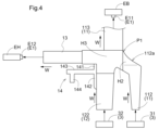
- Fig. 4 and Fig. 5 are diagrams showing the configuration of the switching flow path 13 and its vicinity.
- Fig. 6 is a schematic diagram showing a cross section of the switching flow path 13 and its vicinity cut along the horizontal direction. The direction from top to bottom in Fig. 4 and Fig. 5 corresponds to the vertical direction.
- the switching flow path 13 extends in a horizontal direction perpendicular to the vertical direction.
- the third high-temperature flow path 113 connected to the switching flow path 13 extends obliquely upward from the switching flow path 13 as its base end (see also Figure 5).
- the second low-temperature flow path 122 is connected to a portion of the switching flow path 13 downstream of the connection portion P1 with the second high-temperature flow path 112.
- the second low-temperature flow path 122 extends vertically and is connected to the switching flow path 13 so as to be perpendicular to the extension direction of the switching flow path 13.
- the cooling water W (the cooling water W with a relatively low dynamic pressure among the high-temperature cooling water W flowing into the switching flow path 13) other than the mainstream of the first-temperature cooling water W flowing from the second high-temperature flow path 112 into the switching flow path 13 (the cooling water W with a relatively high dynamic pressure among the high-temperature cooling water W flowing into the switching flow path 13) faces the cooling water W of the second temperature flowing through the second low-temperature flow path 122, and the cooling water W of the first temperature is prevented from flowing into the second low-temperature flow path 122.
- the second low-temperature flow path 122 is connected to the switching flow path 13 from below in the vertical direction.
- the temperature management device 100 is arranged (vertically arranged) on the vehicle V so that the second high-temperature flow path 112 is connected to the switching flow path 13 from below in the vertical direction.
- gravity acts on the second-temperature cooling water W flowing through the second low-temperature flow path 122, and the second-temperature cooling water W is prevented from flowing into the switching flow path 13, the second high-temperature flow path 112, and the third high-temperature flow path 113, which are located above the second low-temperature flow path 122.
- the difference in specific gravity between the first-temperature cooling water W and the second-temperature cooling water W also prevents the first-temperature cooling water W from flowing into the second low-temperature flow path 122.
- the second high-temperature flow path 112 has a flow rate adjustment section 112a upstream of the connection part P1.
- the flow rate adjustment section 112a is inclined so that the higher it is located, the closer it is to the switching flow path 13.
- the flow rate adjustment section 112a includes a first wall surface H1 located on the side where the third high-temperature flow path 113 extends when viewed in the vertical direction, and a second wall surface H2 facing the first wall surface H1.
- the first wall surface H1 extends in the direction in which the switching flow passage 13 extends, i.e., parallel to the flow direction of the cooling water W.
- the second wall surface H2 is configured such that the upstream side (the side farther from the connection portion P1) approaches the first wall surface H1 and the downstream side (the side closer to the connection portion P1) is separated from the first wall surface H1.
- the portion where the second wall surface H2 is configured to approach the first wall surface H1 (the portion composed of the portion including the first wall surface H1 and the second wall surface H2) is referred to as the "reduced portion 112b"
- the portion where the second wall surface H2 is configured to separate from the first wall surface H1 (the portion composed of the portion including the first wall surface H1 and the second wall surface H2) is referred to as the "enlarged portion 112c”.
- the contraction section 112b is provided upstream of the connection portion P1 (expansion section 112c).
- the contraction section 112b is configured so that the cross-sectional area of the flow path through which the cooling water W flows (hereinafter referred to as the "flow path cross-sectional area") is reduced compared to the upstream side of the contraction section 112b of the second high-temperature flow path 112 (immediately upstream of the contraction section 112b), and the flow rate of a portion of the cooling water W flowing into the switching flow path 13 is increased.
- the contraction section 112b is configured to increase the flow rate of the cooling water W that flows on the first wall surface H1 (third high-temperature flow path 113) side, which is a portion of the cooling water W flowing into the switching flow path 13 and flows through the second high-temperature flow path 112.
- the reduction section 112b constitutes a blocking mechanism that can block the flow of the second temperature cooling water W into the high temperature flow path 11.
- the expansion section 112c is provided downstream of the contraction section 112b and upstream of the connection portion P1.
- the expansion section 112c is configured so that the flow path cross-sectional area through which the cooling water W flows is larger than that of the contraction section 112b.
- the expansion section 112c is configured so that the cooling water W that has passed through the expansion section 112c spreads radially when it flows into the switching flow path 13, and swirls by colliding with the third wall surface H3 that constitutes the switching flow path 13.
- the expansion section 112c is configured so that at least a part of the cooling water W other than the cooling water W whose flow rate increases among the cooling water W that flows into the switching flow path 13, and the cooling water W that flows on the second wall surface H2 (opposite the third high-temperature flow path 113) swirls by colliding with the third wall surface H3 that constitutes the switching flow path 13.
- the expansion section 112c and the third wall surface H3 that constitutes the switching flow path 13 constitute a swirl generating section that swirls the cooling water W.
- the cooling water W swirls around the axis along which the switching flow path 13 extends.
- Figure 7 is a diagram showing the configuration of the lead flow path 14. More specifically, it is a diagram showing the switching flow path 13 and its vicinity shown in Figure 4 as viewed from the opposite side in a horizontal direction perpendicular to the direction in which the switching flow path 13 extends.
- Figure 8 is a diagram showing a temperature sensor unit U in which the lead flow path 14 and the temperature sensor 4 are integrated.
- the lead flow path 14 is provided downstream of the second pump 32.
- the lead flow path 14 includes a first lead flow path 141 connected to the switching flow path 13, a second lead flow path 142 connected to the second low-temperature flow path 122, a junction lead flow path 143 where the first lead flow path 141 and the second lead flow path 142 join, and a return lead flow path 144 connected between the second pump 32 and the radiator 2 (first low-temperature flow path 121).
- the first lead flow path 141 is illustrated as being connected to the switching flow path 13 at a position Q1 upstream of the portion of the switching flow path 13 that connects to the second high-temperature flow path 112.
- the first lead flow path 141 is connected to the switching flow path 13 at a position Q2 downstream of the portion of the switching flow path 13 that connects to the second high-temperature flow path 112.
- a temperature sensor 4 is disposed in the junction lead flow path 143.
- the temperature sensor 4 acquires the temperature of the cooling water W flowing through the junction lead flow path 143 and outputs information indicating that temperature.
- the lead flow path 14 is composed of a groove S formed in the first wall G1 and the second wall G2, and a cover C (see Fig. 8) that covers the groove S.
- the cover C covers the groove S to form a first lead flow path 141, a second lead flow path 142, a junction lead flow path 143, and a return lead flow path 144.
- the first wall G1 is a wall that constitutes the high-temperature flow path 11, the low-temperature flow path 12, and the switching flow path 13, and the second wall G2 is a wall that protrudes from the first wall G1.
- the second wall G2 includes a first extension portion G3 that extends along the extension direction of the switching flow path 13, and a second extension portion G4 that extends in a direction perpendicular to the first extension portion G3.
- the temperature sensor 4 has a temperature sensing portion 41 that is disposed between the groove S (groove S formed in the first extension portion G3 of the second wall G2) that constitutes the merging lead flow path 143 and the cover C (inserted into the groove S).
- the temperature sensing portion 41 is the portion of the temperature sensor 4 that measures the temperature of the cooling water W.
- the length of the first lead flow path 141 is configured to be the same as the length of the second lead flow path 142.
- the length of the first lead flow path 141 is the length between the first lead inlet 14H1, which is the inlet for the cooling water W of the first lead flow path 141, and the connection position P2.
- the length of the second lead flow path 142 is the length between the second lead inlet 14H2, which is the inlet for the cooling water W of the second lead flow path 142, and the connection position P2.
- connection position P2 indicates the position where the first lead inlet 14H1 and the second lead inlet 14H2 are connected to the merging lead flow path 143, i.e., the position where the first lead inlet 14H1 and the second lead inlet 14H2 are merged.
- first lead inlet 14H1 and the second lead inlet 14H2 have a smaller flow path cross-sectional area than the upstream side of the first lead inlet 14H1 and the second lead inlet 14H2 (immediately upstream of the first lead inlet 14H1 and the second lead inlet 14H2).
- first lead inlet 14H1 and the second lead inlet 14H2 are configured to increase the pressure loss of the cooling water W.
- the first lead inlet 14H1 and the second lead inlet 14H2 are set in size so that the difference between the first pressure difference and the second pressure difference is negligible.
- the first lead inlet 14H1 and the second lead inlet 14H2 are set in size sufficiently small so that the difference between the first pressure difference and the second pressure difference is negligible (the flow path cross-sectional area is narrower than the immediately upstream side (orifice shape)).
- the first pressure difference is the difference in pressure of the cooling water W between the first lead inlet 14H1 and the lead outlet 14H3
- the second pressure difference is the difference in pressure of the cooling water W between the second lead inlet 14H2 and the lead outlet 14H3.
- the lead outlet 14H3 is an outlet for the cooling water W from the lead flow path 14.
- first lead flow path 141, the second lead flow path 142, the merging lead flow path 143, and the return lead flow path 144 have constant flow path cross-sectional areas that are equal to each other.
- first lead flow path 141 has the same flow path cross-sectional area as the first lead inlet 14H1
- second lead flow path 142 has the same flow path cross-sectional area as the second lead inlet 14H2
- the return lead flow path 144 has the same flow path cross-sectional area as the lead outlet 14H3.
- the first lead inlet 14H1 is also sized to prevent the flow of the first temperature cooling water W into the lead flow passage 14 from reducing the amount of the first temperature cooling water W supplied to the engine E, thereby preventing a decrease in the warm-up (heating) performance of the engine E.
- first lead inlet 14H1 and the second lead inlet 14H2 are large enough to prevent blockage even if the cooling water W contains foreign matter.
- first lead inlet 14H1 and the second lead inlet 14H2 are set to a size that ensures a flow rate equal to or greater than the lower limit of the flow rate of the cooling water W that can be measured by the temperature sensor 4 (a flow rate that depends on the performance of the temperature sensor 4, and is the minimum flow rate of the cooling water W at which the temperature of the cooling water W can be measured).
- the lower limit of the flow rate of the cooling water W that can be measured by the temperature sensor 4 is, for example, 0.2 L/min.
- FIG. 9 is a diagram showing the configuration of the junction lead flow path 143 and the temperature sensor 4. More specifically, it is a diagram showing a cross section of the junction lead flow path 143 cut along the flow direction of the cooling water W.
- the temperature sensing portion 41 of the temperature sensor 4 includes a rectangular temperature sensing surface 41S that senses the temperature of the cooling water W. In this embodiment, the temperature sensing surface 41S is arranged to extend along the flow direction of the cooling water W.
- the junction lead flow passage 143 includes a protrusion 143t that protrudes toward the temperature sensor 4.
- the protrusion 143t is provided on the inner wall 143s that surrounds the temperature sensor 4 among the inner walls 143s that constitute the junction lead flow passage 143.
- the upstream side of the protrusion 143t is in the shape of a circular arc sector (a sector with a central angle of 90 degrees or approximately 90 degrees).
- the protrusion 143t causes the cooling water W flowing along the inner wall 143s that constitutes the junction lead flow path 143 to collide with, i.e., come into contact with, the temperature sensor 4.
- 32 protrusions 143t are provided, and eight of the 32 protrusions 143t are provided along the circumferential direction of the inner wall 143s that constitutes the merging lead flow path 143, and the protrusions 143t are arranged in four rows along the flow direction of the cooling water W so that they are staggered when viewed from the flow direction.
- Each of the eight protrusions 143t located on the most upstream side (first row) is arranged so that its downstream end coincides with the upstream end of the temperature sensor 4 (temperature sensing part 41).
- the remaining three rows of protrusions 143t on the downstream side are arranged at a predetermined interval.
- each of the protrusions 143t in the fourth row (the eight located on the most downstream side) of the protrusions 143t is arranged so that its downstream end coincides with the downstream end of the temperature sensing part 41 in the flow direction, and the remaining two rows are arranged so that they are equally spaced from the first row and the fourth row.
- the control unit 20 shown in Fig. 1 is an Engine Control Unit (ECU) and has a processor such as a CPU (Central Processing Unit) and a storage area such as a semiconductor memory.
- the processor executes a control program stored in the storage area, causing the control unit 20 to control the operation of each part (pump 3) of the temperature management device 100.
- the control unit 20 switches control over the pump 3 between a warm-up mode and a temperature adjustment mode described with reference to Fig. 2.
- the control unit 20 controls the pressure (discharge rate) of the first pump 31 and the pressure (discharge rate) of the second pump 32 so that the position where the interface F between the cooling water W at the first temperature (the cooling water W flowing through the switching flow path 13) and the cooling water W at the second temperature (the cooling water W flowing through the second low-temperature flow path 122) is formed is between the first lead inlet 14H1 and the second lead inlet 14H2 (midpoint) (see FIG. 7).
- the target position where the interface F is formed in this embodiment, the midpoint between the first lead inlet 14H1 and the second lead inlet 14H2 is referred to as the "target position".
- the control unit 20 determines whether the temperature indicated by the information output from the temperature sensor 4 (hereinafter referred to as the "obtained temperature") is higher than the average temperature, which is the average value of the first temperature and the second temperature, and controls the pressure of the pump 3 according to the result of the determination.
- control unit 20 determines that the acquired temperature is higher than the average temperature, that is, the position where the interface F is formed is upstream of the target position (the low-temperature flow path 12 (second low-temperature flow path 122) side)
- the control unit 20 increases the pressure of the second pump 32.
- the control unit 20 determines that the acquired temperature is lower than the average temperature, that is, the position where the interface F is formed is downstream of the target position (the switching flow path 13 side)
- the control unit 20 decreases the pressure of the second pump 32. Note that when the control unit 20 determines that the acquired temperature is equal to the average temperature, that is, the position where the interface F is formed is the target position, the control unit 20 does not change the pressure of the second pump 32.
- control unit 20 controls the operation of the pump 3 so that the interface F is not formed inside the second high-temperature flow path 112 and the third high-temperature flow path 113, and the second lead inlet 14H2 is provided below the position where the interface F is formed (see FIG. 7).
- the control unit 20, the first pump 31, and the second pump 32 constitute a blocking mechanism capable of blocking the flow of the second temperature cooling water W into the high temperature flow path 11.
- the interface F is formed between the first lead inlet 14H1 and the second lead inlet 14H2, only the cooling water W at the first temperature flows into the engine E through the first engine inlet E11 and the second engine inlet E12. As a result, the engine E can be warmed up efficiently.
- the control unit 20 controls the pressure of the first pump 31 and the pressure of the second pump 32 so that the cooling water W of the first temperature and the cooling water W of the second temperature are mixed in the switching flow path 13.
- the control unit 20 controls the pressure of the first pump 31 and the pressure of the second pump 32 so that the cooling water W of the third temperature, which is a mixture of the cooling water W of the first temperature and the cooling water W of the second temperature, flows through the switching flow path 13.
- the control unit 20 controlling the pressure of the pump 3 as described above, the cooling water W of the third temperature flows into the first lead flow path 141, and the cooling water W of the second temperature flows into the second lead flow path 142.
- the control unit 20 controls the operation of the pump 3, for example, by referring to pump control information (pump map) that indicates information related to the control of the pump 3.
- the pump control information is created in advance by a designer of the temperature management device 100, etc., and is stored in advance in a memory area of the control unit 20.
- the pump control information is, for example, information that indicates a correlation between the amount of heat generated by the engine E, a first target temperature of the cooling water W that is caused to flow into the cylinder head EH, and a target temperature of the cooling water W that flows out from the engine outlet E2 of the engine E (hereinafter referred to as the "second target temperature").
- the second target temperature is, for example, 95 degrees.
- the control unit 20 refers to the pump control information and obtains the first target temperature based on the second target temperature and the amount of heat generated by the engine E.
- the control unit 20 may determine whether the third temperature is higher than the first target temperature, which is the target temperature of the cooling water W to be flowed into the cylinder head EH, and control the pressure (driving force) of the pump 3 according to the result of the determination.
- the third temperature is obtained based on information indicating the temperature output from the temperature sensor 4 and information indicating the second temperature (the temperature of the cooling water W flowing out from the radiator 2).
- control unit 20 determines that the third temperature is higher than the first target temperature, it increases the pressure of the second pump 32. On the other hand, if the control unit 20 determines that the third temperature is lower than the first target temperature, it decreases the pressure of the second pump 32. As a result, the cooling water W whose temperature has been adjusted to the first target temperature flows into the cylinder head EH from the second engine inlet E12 via the switching flow path 13. Note that if the control unit 20 determines that the third temperature is equal to the first target temperature, it does not change the pressure of the second pump 32.
- the high temperature flow passage 11 (third high temperature flow passage 113) that guides the high temperature (first temperature) cooling water W to the cylinder block EB and the switching flow passage 13 that guides the cooling water W to the cylinder head EH are separately provided, so that the temperatures of the cylinder block EB and the cylinder head EH can be controlled independently.
- the switching flow passage 13 is made to flow with the first temperature cooling water W or the third temperature cooling water W obtained by mixing the first temperature cooling water W and the second temperature cooling water W. In other words, the temperature of the cooling water W flowing through the switching flow passage 13 can be switched. Therefore, the temperature of the engine E can be controlled more precisely.
- the low-temperature flow path 12 (second low-temperature flow path 122) is connected to the switching flow path 13 from below in the vertical direction perpendicular to the horizontal direction, it is easy to control (suppress) the inflow of the cooling water W flowing through the low-temperature flow path 12 into the switching flow path 13.
- the warm-up mode see FIG. 2
- the reduction section 112b, the control section 20, the first pump 31, and the second pump 32 serving as a blocking mechanism can block the flow of the cooling water W flowing through the low-temperature flow path 12 into the high-temperature flow path 11. This makes it easier to manage the temperature of the cooling water W guided to the cylinder block EB (maintaining the temperature of the cooling water W at the first temperature), and allows for more precise management of the temperature of the cylinder block EB.
- the reduction section 112b is configured so that the flow rate of the cooling water W flowing on the first wall surface H1 (third high-temperature flow path 113) side, which is a portion of the cooling water W flowing into the switching flow path 13 and flowing through the second high-temperature flow path 112, is increased, and the cooling water W with the increased flow rate is prevented from flowing into the third high-temperature flow path 113 at the switching flow path 13 with the second temperature.
- temperature management of the cooling water W guided to the cylinder block EB becomes easier, and the temperature of the cylinder block EB can be managed more precisely.
- the expansion section 112c is configured so that the cooling water W flowing into the switching flow path 13 collides with the third wall surface H3 constituting the switching flow path 13 and swirls, so that the cooling water W at the first temperature and the cooling water W at the second temperature are mixed well, and the temperature distribution of the cooling water W flowing through the switching flow path 13 can be made uniform.
- the temperature of the cooling water W at the third temperature flowing from the switching flow path 13 through the first lead flow path 141 into the junction lead flow path 143 becomes constant.
- the temperature of the cooling water W (third temperature) acquired by the temperature sensor 4 becomes more accurate.
- the length of the first lead flow path 141 is configured to be the same as the length of the second lead flow path 142, the flow rate of the cooling water W flowing through the first lead flow path 141 and the flow rate of the cooling water W flowing through the second lead flow path 142 can be made equal.
- the temperature sensor 4 arranged in the merging lead flow path 143 to obtain the average value of the temperature of the cooling water W flowing through the first lead flow path 141 and the temperature of the cooling water W flowing through the second lead flow path 142.
- the temperature of the cooling water W flowing through the first lead flow path 141 and the temperature of the cooling water W flowing through the second lead flow path 142 can be obtained more accurately. Therefore, the temperature of the engine E can be managed more precisely.
- the first lead inlet 14H1 and the second lead inlet 14H2 are configured so that the flow path cross-sectional area is reduced, that is, the pressure loss of the cooling water W is increased. Therefore, the flow rate of the cooling water W in the first lead flow path 141 flowing into the merging lead flow path 143 can be made equal to the flow rate of the cooling water W in the second lead flow path 142.
- the size of the first lead inlet 14H1 and the second lead inlet 14H2 is set to a size (small) such that the difference between the first pressure difference and the second pressure difference can be ignored, so that the flow rate of the cooling water W flowing through the first lead flow path 141 can be made equal to the flow rate of the cooling water W flowing through the second lead flow path 142.
- the cooling water W comes into contact with the temperature sensor 4, it exchanges heat with the temperature sensor 4 and is heated. For this reason, if the protrusion 143t is not provided on the merging lead flow path 143, the cooling water W after heat exchange with the temperature sensor 4 and heating up flows along the temperature sensor 4 (temperature sensor 41), and the temperature of the cooling water W measured by the temperature sensor 4 may be inaccurate.
- the cooling water W fresh cooling water W
- the cooling water W that has been heated by heat exchange with the temperature sensor 4 is pushed away from the temperature sensor 4 (temperature sensor 41).
- the lead flow path 14 is composed of the groove S and the cover C that covers the groove S, so the lead flow path 14 and the temperature sensor 4 can be constructed easily. Moreover, since it is only necessary to place the temperature sensor 4 between the groove S and the cover C, the assembly of the temperature sensor 4 can be facilitated.
- the control unit 20 controls the operation of the first pump 31 and the second pump 32 so that the position where the interface F between the first temperature coolant W and the second temperature coolant W is formed is between the first lead inlet 14H1 and the second lead inlet 14H2. This makes it possible to obtain the temperature of the coolant W more accurately. As a result, the temperature of the engine E can be managed more precisely.
- the second high-temperature flow passage 112 may include a branch portion 112B, which may be connected to the switching flow passage 13.
- the branch portion 112B is inclined upward as it approaches the switching flow passage 13. This prevents the coolant W at the first temperature from flowing into the second low-temperature flow passage 122, thereby preventing a decrease in the warm-up performance of the engine E.
- the direction from top to bottom in FIG. 10 corresponds to the vertical direction.
- a baffle plate 112J, a stirring unit 112K such as a stirring tank 112T, etc. may be provided inside the second high-temperature flow path 112 (branching portion 112B) to more efficiently stir the cooling water W flowing into the switching flow path 13.
- the stirring unit 112K may be provided in the flow rate adjustment unit 112a described with reference to FIG. 6.
- the cooling water W that has passed through the temperature sensor 4 is returned between the radiator 2 and the second pump 32.
- the cooling water W that has passed through the temperature sensor 4 may be returned to a position in the first high-temperature flow path 111 that is upstream of the first pump 31 and downstream of the branch point with the fourth high-temperature flow path 114.
- the engine E has been described as an example of a temperature management target, but the temperature management target is not limited to the engine E.
- the temperature management target may be, for example, a rechargeable battery such as a nickel-metal hydride battery or a lithium-ion battery, or a fuel cell that generates electricity through a chemical reaction.
- cooling water W has been described as an example of a fluid, but the fluid may be a fluid other than cooling water W, such as a paraffin-based insulating oil, a hydrofluorocarbon (HFC), a hydrofluoroolefin (HFO), or other refrigerant.
- a paraffin-based insulating oil such as a paraffin-based insulating oil, a hydrofluorocarbon (HFC), a hydrofluoroolefin (HFO), or other refrigerant.
- HFC hydrofluorocarbon
- HFO hydrofluoroolefin
- the switching flow path 13 extends horizontally, but the switching flow path 13 does not have to extend horizontally and may be inclined with respect to the horizontal direction, for example.
- the second low-temperature flow path 122 is not limited to being connected to the switching flow path 13 from below in the vertical direction, and may be connected to the switching flow path 13 from, for example, diagonally below.
- the second high-temperature flow path 112 may omit the contraction section 112b and configure a cutoff mechanism only by controlling the pump 3. Also, the second high-temperature flow path 112 may omit the expansion section 112c.
- the first lead flow passage 141 and the second lead flow passage 142 need not be configured to have the same length as long as they are configured so that the flow rates of the cooling water W flowing into them are equal.
- the sizes of the first lead inlet 14H1 and the second lead inlet 14H2 need not be configured so that the flow rates of the cooling water W flowing into the first lead flow passage 141 and the second lead flow passage 142 are equal, and the flow passage cross-sectional area does not need to be smaller than the upstream of each of the first lead inlet 14H1 and the second lead inlet 14H2.
- the number of protrusions 143t can be changed as appropriate.
- the number of protrusions 143t provided along the circumferential direction is not limited to eight, and may be four, six, etc.
- the number of protrusions 143t provided along the flow direction is not limited to four rows, and may be six rows, eight rows, etc.
- the eight protrusions 143t located on the most upstream side do not have to be provided so that their downstream ends coincide with the upstream end of the temperature sensor 4 (temperature sensing section 41).
- the downstream end of the protrusion 143t (fourth row) located on the most downstream side does not have to coincide with the downstream end of the temperature sensing section 41.
- the eight protrusions 143t do not have to be provided at equal intervals along the flow direction.
- the junction lead flow path 143 can omit the protrusions 143t.
- the shape of the temperature sensing surface 41S is not limited to a rectangular shape. The shape of the temperature sensing surface 41S may be, for example, an ellipse, a circle, a sector, etc.
- the lead flow passage 14 is configured with a groove S and a cover C, but the lead flow passage 14 may be configured with a cylindrical tube or the like, and the temperature sensor 4 may be disposed (inserted) inside the tube.
- the control unit 20 controls the position where the interface F is formed to be the target position by adjusting the pressure of the second pump 32.
- the control unit 20 may control the position where the interface F is formed to be the target position by changing the pressure of the first pump 31.
- the control unit 20 may control the position where the interface F is formed to be the target position by changing both the pressure of the first pump 31 and the pressure of the second pump 32.
- the temperature adjustment mode only the pressure of the first pump 31 may be changed, or both the pressure of the first pump 31 and the pressure of the second pump 32 may be changed, so that the cooling water W at the first temperature and the cooling water W at the second temperature are mixed in the switching flow path 13.
- the first lead flow path 141, the second lead flow path 142, the junction lead flow path 143, and the reflux lead flow path 144 have constant flow path cross-sectional areas that are equal to each other.
- the first lead flow path 141, the second lead flow path 142, the junction lead flow path 143, and the reflux lead flow path 144 do not have to have constant flow path cross-sectional areas or be equal to each other.
- it is preferable that the flow path cross-sectional areas of the first lead flow path 141 and the second lead flow path 142 are constant and equal to each other.
- the flow path area of the first lead flow path 141 may be different from that of the first lead inlet 14H1
- the flow path area of the second lead flow path 142 may be different from that of the second lead inlet 14H2
- the flow path area of the reflux lead flow path 144 may be different from that of the lead outlet 14H3.
- the characteristic of the temperature management device 100 disclosed herein is that the temperature management device 100 manages the temperature of an engine E having a cylinder block EB (first managed object) and a cylinder head EH (second managed object) by circulating a fluid W, and includes a first pump 31 that transfers the fluid W at a first temperature that is heated by the engine E, a second pump 32 that transfers the fluid W at a second temperature that is lower than the first temperature, and a second pump 32 that transfers the fluid W at the first temperature transferred by the first pump 31 to the cylinder block EB.
- the high-temperature flow path 11 leads to the cylinder head EB (first management object), a low-temperature flow path 12 (second flow path) through which a fluid W of a second temperature transported by a second pump 32 flows, and a switching flow path 13 connected to the high-temperature flow path 11 (first flow path) and the low-temperature flow path 12 (second flow path) and switching the temperature of the fluid W led to the cylinder head EH (second management object), where the switching flow path 13 is a point where a fluid W of the first temperature or a fluid W of a third temperature, which is a mixture of the fluid W of the first temperature and the fluid W of the second temperature, flows.
- a high-temperature flow path 11 that guides the fluid W at the first temperature to the cylinder block EB (first managed object) and a switching flow path 13 that guides the fluid W at the first temperature to the cylinder head EH (second managed object) are provided separately.
- the temperatures of the cylinder block EB (first managed object) and the cylinder head EH (second managed object) are managed independently.
- the switching flow path 13 allows the fluid W at the first temperature, or the fluid W at the third temperature, which is a mixture of the fluid W at the first temperature and the fluid W at the second temperature, to flow. In other words, the temperature of the fluid W flowing through the switching flow path 13 can also be switched. This allows the temperature of the engine E to be managed more precisely.
- the switching flow path 13 may extend in the horizontal direction, and the low-temperature flow path 12 (second flow path) may be connected to the switching flow path 13 from below in a vertical direction perpendicular to the horizontal direction.
- the low-temperature flow path 12 (second flow path) is connected to the switching flow path 13 from below in the vertical direction perpendicular to the horizontal direction, making it easier to control (suppress) the inflow of the fluid W flowing through the low-temperature flow path 12 (second flow path) into the switching flow path 13.
- This makes it easier to manage the temperature of the fluid W guided to the cylinder head EH (second managed object) via the switching flow path 13, allowing for more precise management of the temperature of the cylinder head EH (second managed object).
- the temperature management device 100 described in (1) or (2) may further include a reduction section 112b (blocking mechanism) capable of blocking the flow of the second temperature fluid W into the high temperature flow path 11 (first flow path).
- a reduction section 112b blocking mechanism capable of blocking the flow of the second temperature fluid W into the high temperature flow path 11 (first flow path).
- the flow of fluid W flowing through the low-temperature flow path 12 (second flow path) into the high-temperature flow path 11 (first flow path) can be blocked by the reduction section 112b (blocking mechanism).
- This makes it easier to manage the temperature of the fluid W guided to the cylinder block EB (first managed object) (maintaining the temperature of the fluid W at a high temperature), and allows for more precise management of the temperature of the cylinder block EB (first managed object).
- the high-temperature flow path 11 (first flow path) is provided upstream of the connection part P1 with the switching flow path 13 in the flow direction of the fluid W, and has a reduction section 112b in which the flow path cross-sectional area is reduced compared to the upstream side, and the reduction section 112b may constitute a blocking mechanism capable of blocking the flow of the fluid W of the second temperature into the high-temperature flow path 11 (first flow path) by increasing the flow rate of the fluid W of the first temperature flowing into the switching flow path 13.
- the reduction section 112b is configured to increase the flow rate of the fluid W flowing into the switching flow path 13, and the increased flow rate of the fluid W suppresses the inflow of the fluid W flowing through the low-temperature flow path 12 (second flow path) into the high-temperature flow path 11 (first flow path).
- the simple configuration of forming the reduction section 112b makes it easier to manage the temperature of the fluid W guided to the cylinder block EB (first managed object), and allows for more precise management of the temperature of the cylinder block EB (first managed object).
- the high-temperature flow path 11 (first flow path) has an expansion section 112c downstream of the contraction section 112b and upstream of the switching flow path 13, in which the flow path cross-sectional area is larger than that of the contraction section 112b, and the expansion section 112c may be configured so that the fluid W flowing into the switching flow path 13 collides with a third wall surface H3 (wall surface) that constitutes the switching flow path 13 and rotates.
- the expansion section 112c is configured so that the fluid W flowing into the switching flow path 13 collides with the third wall surface H3 (wall surface) that constitutes the switching flow path 13 and swirls, so that the fluid W at the first temperature and the fluid W at the second temperature are mixed well, and the temperature distribution of the fluid W flowing through the switching flow path 13 can be made uniform.
- the temperature management device 100 may further include a temperature sensor 4 (sensor) that acquires the temperature of the fluid W, and a lead flow path 14 that guides the fluid W to the temperature sensor 4 (sensor).
- the lead flow path 14 may have a first lead flow path 141 connected to the switching flow path 13, a second lead flow path 142 connected to the low-temperature flow path 12 (second flow path), and a junction lead flow path 143 where the first lead flow path 141 and the second lead flow path 142 join and where the temperature sensor 4 (sensor) is located.
- the length of the first lead flow path 141 may be configured to be the same as the length of the second lead flow path 142.
- the flow rate of the fluid W flowing through the first lead flow path 141 can be made equal to the flow rate of the fluid W flowing through the second lead flow path 142.
- the temperature of the fluid W flowing through the first lead flow path 141 and the temperature of the fluid W flowing through the second lead flow path 142 can be obtained more accurately. Therefore, the temperature for the engine E can be managed more precisely.
- the first lead inlet 14H1 which is the inlet for fluid W of the first lead flow path 141
- the second lead inlet 14H2 which is the inlet for fluid W of the second lead flow path 142
- the first lead inlet 14H1 and the second lead inlet 14H2 may have a smaller flow path cross-sectional area than the upstream side of the first lead inlet 14H1 and the second lead inlet 14H2.
- the flow path cross-sectional area of the first lead inlet 14H1 and the second lead inlet 14H2 is reduced, i.e., the first lead inlet 14H1 and the second lead inlet 14H2 are configured to increase the pressure loss of the fluid W.
- the difference between the pressure of the fluid W flowing through the first lead flow path 141 and the pressure of the fluid W flowing through the second lead flow path 142 becomes negligibly small, and the flow rate of the first lead flow path 141 flowing into the merging lead flow path 143 can be made equal to the flow rate of the second lead flow path 142.
- the junction lead passage 143 may include a protrusion 143t that protrudes toward a temperature sensor 4 (sensor) arranged in the junction lead passage 143.
- the fluid W fresh fluid W
- the fluid W that has not undergone heat exchange with the temperature sensor 4 (sensor) is guided to the protrusion 143t and comes into contact with the temperature sensor 4 (sensor).
- the fluid W that has been heated through heat exchange with the temperature sensor 4 (sensor) is pushed away from the temperature sensor 4 (sensor).
- This increases the amount of heat transfer between the temperature sensor 4 (sensor) and the fluid W.
- the temperature of the fluid W can be accurately measured.
- the lead flow path 14 is composed of a groove S formed in a first wall G1 and a second wall G2 protruding from the first wall G1 that constitute the high-temperature flow path 11 (first flow path), the low-temperature flow path 12 (second flow path), and the switching flow path 13, and a cover C that covers the groove S, and the temperature sensor 4 (sensor) may be disposed between the groove S and the cover C.
- the lead flow path 14 is composed of a groove S formed in the wall and a cover C that covers the groove S, so the lead flow path 14 and the temperature sensor 4 can be easily configured.
- the assembly of the temperature sensor 4 can be easily performed.
- the temperature management device 100 described in (7) may further include a control unit 20 that controls the operation of the first pump 31 and the second pump 32, and the control unit 20 may control the operation of the first pump 31 and the second pump 32 so that the position where the interface F between the fluid W at the first temperature and the fluid W at the second temperature is formed is between the first lead inlet 14H1 and the second lead inlet 14H2.
- This disclosure can be used in temperature control devices.
Landscapes
- Engineering & Computer Science (AREA)
- Chemical & Material Sciences (AREA)
- Combustion & Propulsion (AREA)
- Mechanical Engineering (AREA)
- General Engineering & Computer Science (AREA)
- Temperature-Responsive Valves (AREA)
- Cooling Or The Like Of Electrical Apparatus (AREA)
Priority Applications (2)
| Application Number | Priority Date | Filing Date | Title |
|---|---|---|---|
| EP24756527.8A EP4667718A1 (en) | 2023-02-14 | 2024-01-12 | Temperature management device |
| CN202480011238.6A CN120641642A (zh) | 2023-02-14 | 2024-01-12 | 温度管理装置 |
Applications Claiming Priority (2)
| Application Number | Priority Date | Filing Date | Title |
|---|---|---|---|
| JP2023-020528 | 2023-02-14 | ||
| JP2023020528A JP7762174B2 (ja) | 2023-02-14 | 2023-02-14 | 温度管理装置 |
Publications (1)
| Publication Number | Publication Date |
|---|---|
| WO2024171675A1 true WO2024171675A1 (ja) | 2024-08-22 |
Family
ID=92421384
Family Applications (1)
| Application Number | Title | Priority Date | Filing Date |
|---|---|---|---|
| PCT/JP2024/000661 Ceased WO2024171675A1 (ja) | 2023-02-14 | 2024-01-12 | 温度管理装置 |
Country Status (4)
| Country | Link |
|---|---|
| EP (1) | EP4667718A1 (https=) |
| JP (1) | JP7762174B2 (https=) |
| CN (1) | CN120641642A (https=) |
| WO (1) | WO2024171675A1 (https=) |
Citations (8)
| Publication number | Priority date | Publication date | Assignee | Title |
|---|---|---|---|---|
| JPH0586861A (ja) * | 1991-09-20 | 1993-04-06 | Mazda Motor Corp | エンジンの冷却装置 |
| JP2000315513A (ja) * | 1999-05-06 | 2000-11-14 | Nissan Motor Co Ltd | 燃料電池自動車用ラジエータシステム |
| JP2011169273A (ja) | 2010-02-19 | 2011-09-01 | Mitsubishi Motors Corp | 内燃機関 |
| JP2011169237A (ja) * | 2010-02-18 | 2011-09-01 | Isuzu Motors Ltd | 内燃機関の冷却制御システム |
| JP2011190742A (ja) * | 2010-03-15 | 2011-09-29 | Denso Corp | 内燃機関用排気再循環装置 |
| JP2011256736A (ja) * | 2010-06-07 | 2011-12-22 | Nippon Soken Inc | 内燃機関の冷却システム |
| JP2019023059A (ja) * | 2017-07-24 | 2019-02-14 | 株式会社デンソー | 冷却水回路 |
| US11092063B1 (en) * | 2020-03-12 | 2021-08-17 | Ford Global Technologies, Llc | Systems and methods for engine pre-chamber coolant flow |
-
2023
- 2023-02-14 JP JP2023020528A patent/JP7762174B2/ja active Active
-
2024
- 2024-01-12 WO PCT/JP2024/000661 patent/WO2024171675A1/ja not_active Ceased
- 2024-01-12 CN CN202480011238.6A patent/CN120641642A/zh active Pending
- 2024-01-12 EP EP24756527.8A patent/EP4667718A1/en active Pending
Patent Citations (8)
| Publication number | Priority date | Publication date | Assignee | Title |
|---|---|---|---|---|
| JPH0586861A (ja) * | 1991-09-20 | 1993-04-06 | Mazda Motor Corp | エンジンの冷却装置 |
| JP2000315513A (ja) * | 1999-05-06 | 2000-11-14 | Nissan Motor Co Ltd | 燃料電池自動車用ラジエータシステム |
| JP2011169237A (ja) * | 2010-02-18 | 2011-09-01 | Isuzu Motors Ltd | 内燃機関の冷却制御システム |
| JP2011169273A (ja) | 2010-02-19 | 2011-09-01 | Mitsubishi Motors Corp | 内燃機関 |
| JP2011190742A (ja) * | 2010-03-15 | 2011-09-29 | Denso Corp | 内燃機関用排気再循環装置 |
| JP2011256736A (ja) * | 2010-06-07 | 2011-12-22 | Nippon Soken Inc | 内燃機関の冷却システム |
| JP2019023059A (ja) * | 2017-07-24 | 2019-02-14 | 株式会社デンソー | 冷却水回路 |
| US11092063B1 (en) * | 2020-03-12 | 2021-08-17 | Ford Global Technologies, Llc | Systems and methods for engine pre-chamber coolant flow |
Also Published As
| Publication number | Publication date |
|---|---|
| JP7762174B2 (ja) | 2025-10-29 |
| JP2024115065A (ja) | 2024-08-26 |
| EP4667718A1 (en) | 2025-12-24 |
| CN120641642A (zh) | 2025-09-12 |
Similar Documents
| Publication | Publication Date | Title |
|---|---|---|
| JP5223389B2 (ja) | 内燃機関の冷却装置 | |
| CN101889136B (zh) | 内燃机 | |
| EP1239129A2 (en) | Cooling system for water-cooled internal combustion engine and control method applicable to cooling system therefor | |
| JP6096492B2 (ja) | エンジンの冷却装置 | |
| JP6306529B2 (ja) | 車両用内燃機関の冷却装置及び制御方法 | |
| JP5742702B2 (ja) | 冷却装置の制御装置 | |
| JP5541371B2 (ja) | エンジンの冷却装置 | |
| JP2007218115A (ja) | エンジンの冷却装置 | |
| JP2018188999A (ja) | 内燃機関の冷却装置 | |
| WO2024171675A1 (ja) | 温度管理装置 | |
| CN117514538A (zh) | 废气再循环的冷却系统及其控制方法和汽车 | |
| CN111465753A (zh) | 发动机 | |
| KR101906104B1 (ko) | 차량용 엔진의 냉각시스템 및 방법 | |
| JP5637964B2 (ja) | 内燃機関の冷却構造 | |
| JP2005188323A (ja) | エンジンの暖機装置 | |
| US10858981B2 (en) | Water jacket of engine and engine cooling system having the same | |
| CN223707763U (zh) | 冷却系统和车辆 | |
| JP2006132469A (ja) | Egrガスの冷却装置 | |
| KR102060057B1 (ko) | 판형 열교환기를 갖는 차량용 프리히터 | |
| JP6641940B2 (ja) | 内燃機関の吸気冷却装置 | |
| JPH10238343A (ja) | 車両用ラジエータ | |
| CN112002925A (zh) | 燃料电池汽车管理系统及其控制方法 | |
| JP6372341B2 (ja) | インタークーラ制御装置 | |
| CN119933887B (zh) | 缸体结构和车辆 | |
| JP5278372B2 (ja) | 車両の冷却装置 |
Legal Events
| Date | Code | Title | Description |
|---|---|---|---|
| 121 | Ep: the epo has been informed by wipo that ep was designated in this application |
Ref document number: 24756527 Country of ref document: EP Kind code of ref document: A1 |
|
| WWE | Wipo information: entry into national phase |
Ref document number: 202480011238.6 Country of ref document: CN |
|
| WWP | Wipo information: published in national office |
Ref document number: 202480011238.6 Country of ref document: CN |
|
| WWE | Wipo information: entry into national phase |
Ref document number: 2024756527 Country of ref document: EP |
|
| NENP | Non-entry into the national phase |
Ref country code: DE |
|
| ENP | Entry into the national phase |
Ref document number: 2024756527 Country of ref document: EP Effective date: 20250915 |
|
| WWP | Wipo information: published in national office |
Ref document number: 2024756527 Country of ref document: EP |