WO2024166887A1 - 生体センサシステム、生体センサ、端末装置および生体センサシステムの生体データ管理方法 - Google Patents
生体センサシステム、生体センサ、端末装置および生体センサシステムの生体データ管理方法 Download PDFInfo
- Publication number
- WO2024166887A1 WO2024166887A1 PCT/JP2024/003789 JP2024003789W WO2024166887A1 WO 2024166887 A1 WO2024166887 A1 WO 2024166887A1 JP 2024003789 W JP2024003789 W JP 2024003789W WO 2024166887 A1 WO2024166887 A1 WO 2024166887A1
- Authority
- WO
- WIPO (PCT)
- Prior art keywords
- biosensor
- time
- measurement
- transfer request
- counter
- Prior art date
- Legal status (The legal status is an assumption and is not a legal conclusion. Google has not performed a legal analysis and makes no representation as to the accuracy of the status listed.)
- Ceased
Links
Images





Classifications
-
- A—HUMAN NECESSITIES
- A61—MEDICAL OR VETERINARY SCIENCE; HYGIENE
- A61B—DIAGNOSIS; SURGERY; IDENTIFICATION
- A61B5/00—Measuring for diagnostic purposes; Identification of persons
-
- A—HUMAN NECESSITIES
- A61—MEDICAL OR VETERINARY SCIENCE; HYGIENE
- A61B—DIAGNOSIS; SURGERY; IDENTIFICATION
- A61B5/00—Measuring for diagnostic purposes; Identification of persons
- A61B5/24—Detecting, measuring or recording bioelectric or biomagnetic signals of the body or parts thereof
- A61B5/316—Modalities, i.e. specific diagnostic methods
- A61B5/318—Heart-related electrical modalities, e.g. electrocardiography [ECG]
- A61B5/332—Portable devices specially adapted therefor
-
- A—HUMAN NECESSITIES
- A61—MEDICAL OR VETERINARY SCIENCE; HYGIENE
- A61B—DIAGNOSIS; SURGERY; IDENTIFICATION
- A61B5/00—Measuring for diagnostic purposes; Identification of persons
- A61B5/24—Detecting, measuring or recording bioelectric or biomagnetic signals of the body or parts thereof
- A61B5/316—Modalities, i.e. specific diagnostic methods
- A61B5/318—Heart-related electrical modalities, e.g. electrocardiography [ECG]
- A61B5/333—Recording apparatus specially adapted therefor
Definitions
- the present invention relates to a biosensor system, a biosensor, a terminal device, and a method for managing biodata of the biosensor system.
- Wearable biosensors that are attached to a living body to acquire bioinformation such as electrocardiogram signals are known.
- This type of biosensor has an acquisition unit that acquires bioinformation via electrodes attached to the living body, a memory in which the bioinformation acquired by the acquisition unit is stored, a control unit that controls reading and writing of the memory, an external terminal, and a battery.
- the bioinformation stored in the memory is transferred to a PC or the like via a reading device connected to the external terminal and analyzed (see, for example, Patent Document 1).
- Biometric information analyzed by a PC or the like needs to be linked to the time the biometric information was acquired.
- the linking of the biometric information to the time it was acquired is performed by a clock installed in the biometric sensor.
- the time on the clock is adjusted before the biometric sensor is shipped, so there is a risk that the battery will be depleted before the acquisition of the biometric information begins.
- the linking of the biometric information to the time it was acquired can also be performed by operating a timer installed in the biometric sensor when the acquisition of the biometric information begins and recording the acquisition start time on paper or the like. However, if the acquisition start time is not recorded accurately, there is a risk that accurate analysis will not be possible. Furthermore, human labor is required to link the biometric information to the time it was acquired.
- the present invention has been made in consideration of the above points, and aims to accurately link biometric information with the time at which the biometric information was acquired while reducing battery consumption.
- the biosensor system includes a biosensor including a control unit that controls the measurement of bioinformation input through electrodes attached to a living body, a memory in which the measured bioinformation is stored, a counter that operates at a predetermined cycle, and a battery that supplies power to the control unit, the memory, and the counter, a terminal device that transmits a data transfer request to the biosensor and receives the biodata stored in the memory that is transferred from the biosensor in response to the data transfer request, and an interface that interconnects the biosensor and the terminal device, and one of the biosensor and the terminal device determines the measurement start time of the biodata based on the time of occurrence of the data transfer request, the measurement time of the bioinformation, and a first count value of the counter from the completion of the measurement of the bioinformation to the time when the biosensor receives the data transfer request, or based on the time of occurrence of the data transfer request and a second count value of the counter from the start of the measurement of the bioinformation to the time when the biosensor receive
- the disclosed technology makes it possible to accurately link biometric information with the time at which the biometric information was acquired while minimizing battery consumption.
- FIG. 1 is an overall configuration diagram illustrating an example of a biosensor system according to a first embodiment
- 2 is an overall flow diagram showing an example from the start of measurement of biometric data by the biosensor of FIG. 1 to the output of the biometric data.
- FIG. 2 is a flow diagram illustrating an example of the operation of the biosensor of FIG. 1.
- FIG. 4 is a flow chart showing a continuation of FIG. 3 .
- FIG. 2 is a flow diagram showing an example of the operation of the terminal device of FIG. 1 .
- FIG. 11 is an overall flow diagram showing an example of a process from the start of measurement of biometric data by a biosensor to the output of the biometric data in a biosensor system according to a second embodiment.
- FIG. 11 is an overall flow diagram showing an example of a process from the start of measurement of biometric data by a biosensor to the output of the biometric data in a biosensor system according to a second embodiment.
- FIG. 13 is an overall flow diagram showing an example of a process from the start of measurement of biometric data by a biosensor to the output of the biometric data in a biosensor system according to a third embodiment.
- FIG. 8 is a flow diagram illustrating an example of the operation of the biosensor of FIG. 7 .
- FIG. 9 is a flow chart showing a continuation of FIG. 8 .
- FIG. 8 is a flow diagram showing an example of the operation of the terminal device of FIG. 7 .
- FIG. 13 is an overall flow diagram showing an example of a process from the start of measurement of biometric data by a biosensor to the output of the biometric data in a biosensor system according to a fourth embodiment.
- FIG. 1 is an overall configuration diagram showing an example of a biosensor system according to a first embodiment.
- the biosensor system 100 shown in FIG. 1 includes a biosensor 200, a terminal device 300, and a cable 400 that interconnects the biosensor 200 and the terminal device 300.
- the biosensor 200 is a wearable electrocardiograph.
- the biosensor 200 is not limited to an electrocardiograph, and may be any wearable sensor that is attached to a living body and periodically measures bioinformation.
- the biosensor 200 While the biosensor 200 is measuring biometric data, the biosensor 200 is not connected to the terminal device 300. After measuring the biometric data, the biosensor 200 is removed from the living body and connected to the terminal device 300 by a cable 400 as shown in FIG. 1, and transfers the biometric data to the terminal device 300.
- the biosensor 200 has a controller 210 including a counter 211, a flash memory 220, a battery 230, a trigger button 240, a power button 250, a pair of electrodes 261, 262, and a connector 270.
- the connector 270 is an example of an interface that interconnects the biosensor 200 and the terminal device 300.
- the counter 211 counts at a predetermined cycle and updates the count value.
- the counter 211 may be configured using a timer.
- the counter 211 may be disposed outside the controller 210 and connected to the controller 210.
- the controller 210, the flash memory 220, and the connector 270 are interconnected via a signal line SIG.
- the controller 210 and the flash memory 220 are connected to the battery 230 via a direct current power line DC, and operate on the power supplied from the battery 230. If the operating voltages of the controller 210 and the flash memory 220 are different, a voltage converter that converts the direct current voltage output from the battery 230 into multiple types of direct current voltages may be disposed at the output of the battery 230.
- the controller 210 controls the entire biosensor 200, and acquires the biosignals input via the electrodes 261, 262 attached to the living body at a predetermined cycle.
- the controller 210 converts the acquired biosignals into digital biodata, and writes the converted biodata into the flash memory 220 at predetermined intervals.
- the controller 210 is an example of a control unit that controls the measurement of bioinformation input via the electrodes 261, 262 attached to the living body.
- the biosignals and biodata are examples of bioinformation.
- acquiring biosignals from a living body is also referred to as measuring biodata.
- the controller 210 may include, for example, an analog front-end circuit that converts the biometric signal into biometric data, and a control circuit that controls the reading and writing of the biometric data to the flash memory 220 and the sending and receiving of information to and from the terminal device 300.
- the counter 211 starts counting in synchronization with the start of biometric data measurement.
- the count value of the counter 211 is used to manage the size of the biometric data to be written to the flash memory 220, and is also used to calculate the start time of biometric data measurement.
- the counting operation of the counter 211 is explained in FIG. 2.
- the flash memory 220 has multiple pages, each storing multiple bytes of data, and a page buffer that has the same size as each page and holds the data to be written to the page.
- the controller 210 stores the acquired biometric data in the page buffer in sequence, and when one page's worth of biometric data has been stored in the page buffer, it outputs a write command to the flash memory 220 to write the biometric data from the page buffer to one of the multiple pages. The biometric data is then written to the flash memory 220 on a page-by-page basis.
- the controller 210 When the controller 210 receives a data transfer request for biometric data from the terminal device 300 connected by the cable 400, it reads out the biometric data stored in the flash memory 220 in page units. The controller 210 transfers the read biometric data to the terminal device 300 via the signal line SIG and the cable 400. The controller 210 receives the current time from the terminal device 300 along with the data transfer request. The controller 210 calculates the measurement start time of the biometric data based on the received current time and the current count value of the counter 211, and transfers the calculated measurement start time together with the biometric data to the terminal device 300. The method of calculating the measurement start time is described in FIG. 2. The terminal device 300 may directly access the flash memory 220 via the cable 400 and the signal line SIG and read out the biometric data stored in the flash memory 220 without sending a data transfer request to the controller 210.
- the terminal device 300 has a CPU 310 (Central Processing Unit) that includes a biometric data acquisition control unit 311, a memory 320 accessed by the CPU 310, and a connector 330.
- the connector 330 is an example of an interface that interconnects the biometric sensor 200 and the terminal device 300.
- the terminal device 300 is a PC or a server.
- the biometric data acquisition control unit 311 controls the acquisition, from the biometric sensor 200, of biometric data that has been measured by the biometric sensor 200 and stored in the flash memory 220.
- the biometric data acquisition control unit 311 is realized by a control program executed by the CPU 310.
- the biometric data acquisition control unit 311 may be realized by hardware, or may be realized by a combination of hardware and software.
- the biometric data acquisition control unit 311 When acquiring biometric data from the biometric sensor 200, the biometric data acquisition control unit 311 transmits a data transfer request and the current time to the biometric sensor 200 via the cable 400.
- the current time transmitted by the biometric data acquisition control unit 311 to the biometric sensor 200 is an example of the time at which the data transfer request was generated, and is an example of the time at which the data request was received by the biometric sensor 200.
- the biometric data acquisition control unit 311 writes the biometric data and the measurement start time received from the biometric sensor 200 to the memory 320. By acquiring the measurement start time from the biometric sensor 200, the CPU 310 can determine the measurement time of each piece of biometric data written to the memory 320.
- the biosensor 200 and the terminal device 300 may be connected wirelessly.
- the biosensor 200 and the terminal device 300 are each provided with a wireless communication unit instead of the connectors 270 and 330, and the biosensor system 100 does not include the cable 400.
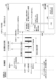
- FIG. 2 is an overall flow diagram showing an example of a process from the start of measurement of biometric data by the biometric sensor 200 in FIG. 1 to the output of the biometric data.
- FIG. 2 shows an example of a biometric data management method for the biometric sensor system.
- the operation of the biometric sensor 200 shown in FIG. 2 shows the operation of the controller 210.
- the biosensor 200 is manufactured at a manufacturing base and sold at a sales base.
- the biosensor 200 is shipped in a low power consumption state (sleep state) in which the counting operation of the counter 211 is stopped, and does not start counting operation until measurement of biometric data is started. This makes it possible to extend the usable period (lifespan) of the biosensor 200 compared to when the counting operation is started at the manufacturing base.
- the biosensor 200 delivered to a medical institution is, for example, turned on and then attached to a patient from whom biometric data is to be acquired.
- the counter 211 starts counting in a first cycle after a first time has elapsed, and starts measuring the biometric data.
- the first time is, for example, five minutes.
- the first cycle is an example of a count cycle of the counter 211.
- the first period corresponds to the time it takes for one page of biometric data to accumulate in the page buffer, and is, for example, approximately 5.3 seconds. Note that in order to make it easier to identify the timing of pressing the trigger button 240 (described later), it is preferable that the first period is approximately 10 seconds or less.
- the first period is set according to the period for acquiring biometric data from a living body, the size of the biometric data acquired at one time, and the page size of the flash memory 220. Then, each time the count value of the counter 211 is updated, the controller 210 writes the biometric data to a page of the flash memory 220, as indicated by the solid black arrow.
- the biometric data can be written to a page of the flash memory 220 in accordance with the time it takes for the biometric data to accumulate in the page buffer. This makes it possible to minimize the amount of biometric data temporarily stored in the controller 210, and to reduce the size of the buffer (not shown) for biometric data mounted on the controller 210. As a result, the cost of the controller 210 can be reduced, and the cost of the biometric sensor 200 can be reduced.
- the biosensor 200 records the event of detecting the pressing of the trigger button 240 as an event flag.
- the biosensor 200 links the recorded event flag to the biometric data acquired when the trigger button 240 was pressed, and stores it together with the biometric data in the flash memory 220. For example, the recording area for the event flag is allocated within a page of the flash memory 220.
- the biosensor 200 When the biosensor 200 completes the measurement of the biodata for the fixed measurement time, it stops the measurement of the biodata and starts the counting operation of the counter 211 in the second cycle.
- the fixed measurement time is 3 days (72 hours).
- the second cycle is an example of the count cycle of the counter 211.
- the second cycle is set in seconds (an integer value such as 5 seconds).
- the counting period of the counter 211 By switching the counting period of the counter 211 from a first period including a decimal point less than a second to a second period of an integer value, it is possible to prevent the accumulation of rounding errors that occur when converting the count value to the count time. This makes it possible to determine the measurement start time of the biological data with high accuracy.
- the patient mails the biometric sensor 200 to the data reception center.
- the biometric sensor 200 continues the counting operation in the second cycle by the counter 211.
- the data reception center is the place where the biometric data is extracted from the biometric sensor 200, and the terminal device 300 is installed.
- a worker at the data reception center connects the biosensor 200 that was mailed to the terminal device 300 with a cable 400.
- the biosensor data acquisition control unit 311 of the terminal device 300 sends a request to transfer the biosensor data together with the current time to the biosensor 200.
- the current time may include not only the hour, minute, and second, but also the year, month, and day. If the current time includes only the hour, minute, and second, the year, month, and day may be managed by the terminal device 300.
- the biosensor 200 which has received the data transfer request and the current time, stops the counting operation in the second cycle by the counter 211. By stopping the counting operation, the power consumption of the biosensor 200 can be reduced. In addition, because the count value when the data transfer request is received is held as is in the counter 211, a memory area for holding the count value can be eliminated, and the process of writing the count value to the memory area can be eliminated.
- the biosensor 200 obtains the measurement start time of the biometric data by subtracting the sum of the time (count time) indicated by the count value of the counter 211 in the second cycle and the fixed measurement time from the received current time.
- the count value of the counter 211 in the second cycle is an example of a first count value.
- the biosensor 200 transmits the obtained measurement start time to the terminal device 300 together with the biometric data stored in the flash memory 220.
- the terminal device 300 stores the received biometric data and the measurement start time in the memory 320.
- the biometric data and the measurement start time are then transferred to a medical institution, and the biometric data is analyzed by a doctor.
- the measurement start time of the biometric data can be accurately determined without linking the count value of counter 211 to time information when the measurement of the biometric data begins. Because the measurement start time can be accurately determined, the time when trigger button 240 is pressed can be determined. As a result, an accurate diagnosis can be made by a doctor. In contrast, if counter 211 is operated in association with time information during the manufacture of biosensor 200, the longer the time until the measurement of the biometric data, the greater the difference between the measurement start time determined from the count value and the actual measurement start time.
- the conventional procedure performed in medical institutions of inputting the time when the biosensor 200 is attached to the patient into a PC or the like and sending the data to a data reception center or the like can be eliminated, reducing the burden on the medical institution (doctor). Also, the patient does not have to write the time when the trigger button 240 is pressed on an action record form or the like, reducing the burden on the patient.
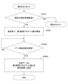
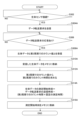
- FIGS. 3 and 4 are flow diagrams showing an example of the operation of the biosensor 200 of FIG. 1.
- the flow shown in FIG. 3 and FIG. 4 is realized by a processor such as an MCU (Micro Controller Unit) mounted on the controller 210 executing a control program for the biosensor 200.
- MCU Micro Controller Unit
- step S202 the biosensor 200 waits until the power button 250 is pressed and held down, and if so, the process proceeds to step S204.
- step S204 the biosensor 200 performs a startup process to cancel the sleep mode and initialize the counter 211, etc.
- step S206 the biosensor 200 waits for a first time (e.g., 5 minutes) to elapse, and when the first time has elapsed, the process proceeds to step S208.
- a first time e.g., 5 minutes
- the biosensor 200 may omit step S206 and perform the process of step S208 without waiting for the first time to elapse.
- step S208 the biosensor 200 starts measuring biometric data and causes the counter 211 to start counting in a first cycle.
- step S210 if the biosensor 200 detects that the trigger button 240 has been pressed, the process proceeds to step S212, and if the biosensor 200 does not detect that the trigger button 240 has been pressed, the process proceeds to step S214.
- step S212 the biosensor 200 records an event flag indicating that the trigger button 240 has been pressed. The event flag when the trigger button 240 has been pressed is written to the flash memory 220 together with the biometric data in step S216.
- step S214 the biosensor 200 determines whether the count value of the counter 211 has been updated. If the count value of the counter 211 has been updated, the biosensor 200 proceeds to step S216 because one page of biometric data in the flash memory 220 has been stored in the page buffer. If the count value of the counter 211 has not been updated, the biosensor 200 returns to step S210 because one page of biometric data in the flash memory 220 has not been stored in the page buffer. In step S216, the biosensor 200 writes the biometric data stored in the page buffer to the flash memory 220. If the biosensor 200 recorded an event flag in step S212, the biosensor 200 writes the event flag to the flash memory 220 together with the biometric data.
- step S218 of FIG. 4 if the fixed measurement time has elapsed, the biosensor 200 transitions the process to step S220, and if the fixed measurement time has not elapsed, the biosensor 200 returns the process to step S210 of FIG. 3.
- step S220 the biosensor 200 ends the measurement of biodata and causes the counter 211 to start counting in the second period. That is, the biosensor 200 switches the count period of the counter 211 from the first period (e.g., 5.3 seconds) to the second period (e.g., 5 seconds).
- the first period e.g., 5.3 seconds
- the second period e.g., 5 seconds
- the biosensor 200 stops operation of the functional units other than the counter 211.
- the functional units other than the counter 211 are an amplifier and an ADC (Analog-to-Digital Converter) included in the analog front-end circuit of the controller 210.
- the amplifier amplifies the signal amount of a weak biosignal input from the living body via the electrodes.
- the ADC converts the analog biosignal amplified by the amplifier into digital biodata.
- step S222 the biosensor 200 waits until it receives a data transfer request and the current time from the terminal device 300, and when it receives the data transfer request and the current time, it transitions to step S224.
- step S224 the biosensor 200 calculates the measurement start time of the biodata by subtracting the sum of the time indicated by the count value of the counter 211 (the count time in the second period) and the fixed measurement time from the received current time.
- step S226 the biosensor 200 stores the obtained measurement start time in the flash memory 220. This allows the measurement start time stored in the flash memory 220 to be transmitted to the terminal device 300 together with the biosensor 200 when retransmitting biodata from the biosensor 200 to the terminal device 300, for example.
- step S228, the biosensor 200 transmits the biodata stored in the flash memory 220 and the determined measurement start time to the terminal device 300, and ends the operation shown in Figs. 3 and 4.
- the terminal device 300 By transmitting the measurement start time from the biosensor 200 to the terminal device 300 along with the biodata, it is possible for the terminal device 300 to easily link the biosensor with the measurement start time. Note that if the count value when the trigger button 240 is pressed is stored in the flash memory 220, the count value is transmitted to the terminal device 300 along with the biodata.
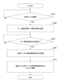
- FIG. 5 is a flow diagram showing an example of the operation of the terminal device in FIG. 1. The flow shown in FIG. 5 is performed by the biometric data acquisition control unit 311.
- step S302 the terminal device 300 waits until the biosensor 200 is connected via the cable 400, and when connected, the process proceeds to step S304.
- step S304 the terminal device 300 transmits a data transfer request and the current time to the biosensor 200.
- step S306 the terminal device 300 waits until it receives a response to the data transfer request, and if it receives a response to the data transfer request, it proceeds to step S308.
- step S308 the terminal device 300 receives the biometric data and the measurement start time from the biometric sensor 200.
- step S310 the terminal device 300 stores the received biometric data and the measurement start time in memory 320, and ends the operation shown in FIG. 5.
- the biosensor 200 determines the measurement start time of the biometric data based on the current time received together with the data transfer request, the measurement time of the biometric data, and the count value in the second cycle of the counter 211. For example, the biosensor 200 determines the measurement start time of the biometric data by subtracting the sum of the time indicated by the count value in the second cycle of the counter 211 and the measurement time of the biometric data from the received current time.
- the measurement start time can be determined without human intervention, the burden on medical institutions (doctors) and patients can be reduced. In addition, because the measurement start time can be determined accurately, the time when the trigger button 240 was pressed can be determined accurately. As a result, doctors can make accurate diagnoses.
- the biometric data can be written to a page of the flash memory 220 in accordance with the time it takes for the biometric data to accumulate in the page buffer. This makes it possible to reduce the size of the buffer for biometric data installed in the controller 210, thereby reducing the cost of the controller 210.
- the count period of the counter 211 By switching the count period of the counter 211 from the first period to the second period, which is an integer value, it is possible to prevent the accumulation of rounding errors that occur when converting the count value to the count time, and to determine the measurement start time of the biological data with high accuracy.
- the measurement start time can be transmitted to the terminal device 300 together with the biometric data.
- the measurement start time By transmitting the measurement start time from the biometric sensor 200 to the terminal device 300 together with the biometric data, it becomes easier for the terminal device 300 to link the biometric sensor with the measurement start time.
- the operation of the functional units other than the counter 211 is stopped, thereby reducing the power consumption of the battery 230 and extending the operating time of the counter 211. If the battery capacity of the battery 230 is reduced instead of extending the operating time of the counter 211, the cost of the biosensor 200 can be reduced.
- FIG. 6 is an overall flow diagram showing an example of a process from the start of measurement of biometric data by a biosensor to the output of the biometric data in a biosensor system according to the second embodiment. Detailed explanations of operations similar to those in FIG. 2 will be omitted.
- FIG. 6 shows an example of a biometric data management method for a biosensor system.
- the operation of the biosensor 200 shown in FIG. 6 is realized by the controller 210 in FIG. 1.
- the operation of the terminal device 300 shown in FIG. 6 is similar to the operation of the terminal device 300 in FIG. 1.
- the biosensor 200 and terminal device 300 shown in FIG. 6 have the same configuration as those in FIG. 1 and operate as the biosensor system 100. However, the way the counter 211 is used and the function of the biodata acquisition control unit 311 are different from those in the first embodiment.
- the biosensor 200 continues the counting operation in the first cycle after measuring the biodata for a fixed measurement time.
- the biosensor 200 stops the counting operation in the first cycle by the counter 211.
- the biosensor 200 obtains the measurement start time of the biodata by subtracting the time indicated by the count value of the counter 211 in the first cycle (count time) from the received current time.
- the operation thereafter is the same as in FIG. 2.
- the count value of the counter 211 in the first cycle is an example of the second count value.
- the operational flow of the biosensor 200 is the same as that shown in Figs. 3 and 4, except that step S220 in Fig. 4 is deleted and the method of calculating the measurement start time in step S224 is different.
- the operational flow of the terminal device 300 is the same as that shown in Fig. 5.
- the biosensor 200 determines the measurement start time of the biometric data based on the current time received together with the data transfer request and the count value of the counter 211 in the first cycle. For example, the biosensor 200 determines the measurement start time of the biometric data by subtracting the time indicated by the count value of the counter 211 in the first cycle from the received current time.
- the biometric data measurement start time can be accurately determined without linking the count value of the counter 211 to time information when the biometric data measurement starts. Since the counter 211 does not need to be linked to time information and operated before the shipment of the biometric sensor 200, consumption of the battery 230 can be suppressed. As a result, it is possible to accurately link the biometric data to the measurement time of the biometric data while suppressing consumption of the battery 230.
- FIG. 7 is an overall flow diagram showing an example of a process from the start of measurement of biometric data by a biometric sensor to the output of the biometric data in a biometric sensor system according to the third embodiment. Detailed explanations of operations similar to those in FIG. 2 will be omitted.
- FIG. 7 shows an example of a biometric data management method for a biometric sensor system.
- the operation of the biometric sensor 200 shown in FIG. 7 is realized by the controller 210 in FIG. 1.
- the operation of the terminal device 300 shown in FIG. 7 is realized by the biometric data acquisition control unit 311 in FIG. 1.
- the biosensor 200 and terminal device 300 shown in FIG. 7 have the same configuration as in FIG. 1 of the first embodiment, and operate as the biosensor system 100. However, in this embodiment, the calculation of the measurement start time is performed by the terminal device 300, and the biosensor 200 does not have the function of calculating the measurement start time.
- the terminal device 300 When the terminal device 300 detects the connection of the biosensor 200, it only sends a data transfer request to the biosensor 200 and does not send the current time.
- the biosensor 200 receives the data transfer request, it stops the counting operation of the counter 211 in the second period.
- the biosensor 200 sends the count value of the counter 211 in the second period to the terminal device 300 together with the biodata.
- the terminal device 300 stores the received biometric data in memory 320.
- the terminal device 300 determines the time of the count operation in the second cycle from the count value in the second cycle.
- the terminal device 300 determines the measurement start time of the biometric data by subtracting the sum of the count time in the second cycle and the fixed measurement time from the transmission time of the data transfer request. The operation thereafter is the same as in FIG. 2.
- the biosensor 200 may determine the count time in the second cycle from the count value in the second cycle, and transmit the determined time to the terminal device 300 together with the biometric data.
- the terminal device 300 can determine the measurement start time of the biometric data without determining the count time in the second cycle.
- FIG. 8 is a flow diagram showing an example of the operation of the biosensor in FIG. 7. The operation shown in FIG. 8 is similar to the operation shown in FIG. 3.
- FIG. 9 is a flow diagram showing a continuation of FIG. 8. Operations similar to those in FIG. 4 are indicated with the same step numbers, and detailed explanations are omitted.
- the biosensor 200 does not perform steps S224 and S226 in FIG. 4, but performs steps S222A and S228A instead of steps S222 and S228 in FIG. 4, respectively.
- step S222A the biosensor 200 waits until it receives a data transfer request from the terminal device 300, and if it receives a data transfer request, it transitions to step S228A.
- step S228A the biosensor 200 transmits the biodata stored in the flash memory 220 and the count value of the counter 211 in the second period to the terminal device 300, and ends the operation shown in Figures 8 and 9.
- FIG. 10 is a flow diagram showing an example of the operation of the terminal device of FIG. 7. The same step numbers are indicated for operations similar to those of FIG. 5, and detailed descriptions are omitted.
- the terminal device 300 performs steps S304A and S308A instead of steps S304 and S308 in FIG. 5, respectively.
- the terminal device 300 performs steps S310A and S316A instead of step S310 in FIG. 5, and performs steps S312A and S314A between steps S310A and S316A.
- step S304A the terminal device 300 transmits a data transfer request to the biosensor 200.
- step S306 the terminal device 300 waits until it receives a response to the data transfer request. If it receives a response to the data transfer request, in step S308A, the terminal device 300 receives the biodata and the count value for the second period from the biosensor 200.
- step S310A the terminal device 300 stores the received biometric data in memory 320.
- step S312A the terminal device 300 obtains the count time in the second cycle from the count value in the second cycle.
- step S314A the terminal device 300 obtains the measurement start time of the biometric data by subtracting the sum of the count time in the second cycle and the fixed measurement time from the transmission time of the data transfer request.
- Step S314A is a process for obtaining the measurement start time that is performed in response to step S224 in FIG. 4.
- step S316A the terminal device 300 stores the measurement start time in memory 320 and ends the operation shown in FIG. 10.
- the terminal device 300 determines the measurement start time of the biometric data based on the transmission time of the data transfer request, the measurement time of the biometric data by the biometric sensor 200, and the count value in the second cycle of the counter 211 received from the biometric sensor 200. For example, the terminal device 300 determines the measurement start time of the biometric data by subtracting the sum of the time indicated by the count value in the second cycle of the counter 211 and the measurement time of the biometric data from the transmission time of the data transfer request.
- the biometric data measurement start time can be accurately determined without linking the count value of the counter 211 to time information when the biometric data measurement starts. Since the counter 211 does not need to be linked to time information and operated before the shipment of the biometric sensor 200, consumption of the battery 230 can be suppressed. As a result, it is possible to precisely link the biometric data to the measurement time of the biometric data while suppressing consumption of the battery 230.
- FIG. 11 is an overall flow diagram showing an example of a process from the start of measurement of biometric data by a biometric sensor to the output of the biometric data in a biometric sensor system according to the fourth embodiment. Detailed explanations of operations similar to those in FIG. 2 and FIG. 7 will be omitted.
- FIG. 11 shows an example of a biometric data management method for a biometric sensor system.
- the operation of the biometric sensor 200 shown in FIG. 11 is realized by the controller 210 in FIG. 1.
- the operation of the terminal device 300 shown in FIG. 11 is realized by the biometric data acquisition control unit 311 in FIG. 1.
- the biosensor 200 and terminal device 300 shown in FIG. 11 have the same configuration as those in FIG. 1 of the first embodiment, and operate as the biosensor system 100.
- the operation of the biosensor 200 is similar to that of the biosensor 200 in FIG. 6, except that it only receives a data transfer request from the terminal device 300 and does not have the function of calculating the measurement start time.
- the operation of the terminal device 300 is similar to that of the terminal device 300 in FIG. 7, except that it receives a count value in a first period from the biosensor 200 and uses the count value in the first period to determine the measurement start time.
- the biosensor 200 measures biodata for a fixed measurement time, and then continues counting in the first cycle.
- the biosensor 200 stops the counting operation in the first cycle by the counter 211, and transmits the count value of the counter 211 in the first cycle together with the biodata to the terminal device 300.
- the terminal device 300 When the terminal device 300 detects the connection of the biosensor 200, it only transmits a data transfer request to the biosensor 200 and does not transmit the current time.
- the terminal device 300 stores the received biosensor data in the memory 320.
- the terminal device 300 obtains the count time in the first cycle from the count value in the first cycle.
- the terminal device 300 then obtains the measurement start time of the biosensor data by subtracting the count time in the first cycle from the transmission time of the data transfer request.
- the terminal device 300 stores the obtained measurement start time in the memory 320.
- the operation flow of the biosensor 200 is the same as that shown in Figs. 8 and 9, except that step S220 in Fig. 9 is deleted, and in step S228A, the biodata and the count value in the first period are transmitted to the terminal device 300.
- the operation flow of the terminal device 300 is the same as that shown in Fig. 10, except that the processing in steps S308A, S312A, and S314A in Fig. 10 is different.
- step S308A of FIG. 10 the terminal device 300 receives biometric data and a count value in the first period.
- step S312A of FIG. 10 the terminal device 300 determines the count time in the first period from the count value in the first period.
- step S314 of FIG. 10 the terminal device 300 determines the measurement start time using the count time in the first period, without using a fixed measurement time.
- the terminal device 300 determines the measurement start time of the biometric data based on the transmission time of the data transfer request and the count value of the counter 211 in the first cycle received from the biometric sensor 200. For example, the terminal device 300 determines the measurement start time of the biometric data by subtracting the time indicated by the count value of the counter 211 in the first cycle from the transmission time of the data transfer request.
- the biometric data measurement start time can be accurately determined without linking the count value of the counter 211 to time information when the biometric data measurement starts. Since the counter 211 does not need to be linked to time information and operated before the shipment of the biometric sensor 200, consumption of the battery 230 can be suppressed. As a result, it is possible to precisely link the biometric data to the measurement time of the biometric data while suppressing consumption of the battery 230.
- a biosensor including a control unit that controls measurement of bioinformation input via electrodes attached to a living body, a memory that stores the measured bioinformation, a counter that operates at a predetermined cycle, and a battery that supplies power to the control unit, the memory, and the counter; a terminal device that transmits a data transfer request to the biosensor and receives the biosensor-stored biosensor data in response to the data transfer request; an interface for connecting the biosensor and the terminal device to each other;
- a biosensor system characterized in that one of the biosensor or the terminal device determines the start time of measurement of the biometric data based on the time of occurrence of the data transfer request, the measurement time of the biometric information, and a first count value of the counter from the completion of measurement of the biometric information to the time when the biometric sensor receives the data transfer request, or based on the time of occurrence of the data transfer request and a second count value of the counter from the start of measurement of the biometric information to the time
- the biosensor system described in ⁇ 1> is characterized in that one of the biosensor or the terminal device determines the measurement start time by subtracting the sum of the measurement time and the time indicated by the first count value from the time when the data transfer request was generated, or by subtracting the time indicated by the second count value from the time when the data transfer request was generated.
- a control unit that controls measurement of biological information input via electrodes attached to a living body; A memory for storing measured biological information; A counter that operates at a predetermined cycle; a battery for supplying power to the control unit, the memory, and the counter; an interface for connecting to a terminal device;
- the control unit is A biosensor characterized by determining the start time of measurement of biometric data based on the time of occurrence of a data transfer request received from the control unit, the measurement time of the biometric information, and a first count value of the counter from the completion of measurement of the biometric information to the reception of the data transfer request, or based on the time of occurrence of the data transfer request and a second count value of the counter from the start of measurement of the biometric information to the reception of the data transfer request.
- ⁇ 4> The biosensor according to ⁇ 3>, wherein the counter counts at a first period during measurement of the bioinformation, and counts at a second period different from the first period after measurement of the bioinformation is completed.
- the first period is set corresponding to a period for writing a predetermined amount of biological information into the memory
- the second period is set in units of seconds.
- the control unit transmits the obtained measurement start time to the terminal device together with the biodata stored in the memory.
- ⁇ 7> The biosensor according to any one of ⁇ 3> to ⁇ 5>, wherein the control unit stores the obtained measurement start time in the memory.
- biosensor The biosensor according to any one of ⁇ 3> to ⁇ 7>, wherein the biosensor stops the counting operation of the counter based on the reception of the data transfer request.
- control unit stops operation of functional units other than the counter based on the lapse of measurement time of the bioinformation.
- an interface connected to a biosensor including a control unit that controls measurement of bioinformation input via electrodes attached to a living body, a memory that stores the measured bioinformation, a counter that operates at a predetermined cycle, and a battery that supplies power to the control unit, the memory, and the counter; a biometric data acquisition control unit that sends a data transfer request to the biometric sensor connected via the interface, and determines the start time of measurement of the biometric data based on the time of occurrence of the data transfer request, the measurement time of the biometric information by the biometric sensor, and a first count value of the counter from the completion of measurement of the biometric information to the time when the biometric sensor receives the data transfer request, or based on the time of occurrence of the data transfer request and a second count value of the counter from the start of measurement of the biometric information by the biometric sensor to the time when the biometric sensor receives the data transfer request.
- a biosensor including a control unit that controls measurement of bioinformation input via electrodes attached to a living body, a memory that stores the measured bioinformation, a counter that operates at a predetermined cycle, and a battery that supplies power to the control unit, the memory, and the counter; a terminal device that transmits a data transfer request to the biosensor and receives the biosensor-stored biosensor data in response to the data transfer request; and an interface for connecting the biosensor and the terminal device to each other,
- a method for managing biometric data of a biosensor system characterized in that the measurement start time of the biometric data is determined by either the biosensor or the terminal device based on the time of occurrence of the data transfer request, the measurement time of the biometric information, and a first count value of the counter from the completion of the measurement of the biometric information to the time when the biosensor receives the data transfer request, or based on the time of occurrence of the data transfer request and a second count value of the counter from the start of the measurement of the biometric information to the time when
Landscapes
- Health & Medical Sciences (AREA)
- Life Sciences & Earth Sciences (AREA)
- Heart & Thoracic Surgery (AREA)
- Medical Informatics (AREA)
- Biophysics (AREA)
- Pathology (AREA)
- Engineering & Computer Science (AREA)
- Biomedical Technology (AREA)
- Veterinary Medicine (AREA)
- Physics & Mathematics (AREA)
- Molecular Biology (AREA)
- Surgery (AREA)
- Animal Behavior & Ethology (AREA)
- General Health & Medical Sciences (AREA)
- Public Health (AREA)
- Cardiology (AREA)
- Measuring And Recording Apparatus For Diagnosis (AREA)
Priority Applications (1)
| Application Number | Priority Date | Filing Date | Title |
|---|---|---|---|
| JP2024576344A JPWO2024166887A1 (https=) | 2023-02-07 | 2024-02-06 |
Applications Claiming Priority (2)
| Application Number | Priority Date | Filing Date | Title |
|---|---|---|---|
| JP2023017077 | 2023-02-07 | ||
| JP2023-017077 | 2023-02-07 |
Publications (1)
| Publication Number | Publication Date |
|---|---|
| WO2024166887A1 true WO2024166887A1 (ja) | 2024-08-15 |
Family
ID=92262501
Family Applications (1)
| Application Number | Title | Priority Date | Filing Date |
|---|---|---|---|
| PCT/JP2024/003789 Ceased WO2024166887A1 (ja) | 2023-02-07 | 2024-02-06 | 生体センサシステム、生体センサ、端末装置および生体センサシステムの生体データ管理方法 |
Country Status (2)
| Country | Link |
|---|---|
| JP (1) | JPWO2024166887A1 (https=) |
| WO (1) | WO2024166887A1 (https=) |
Citations (7)
| Publication number | Priority date | Publication date | Assignee | Title |
|---|---|---|---|---|
| WO2011099162A1 (ja) * | 2010-02-15 | 2011-08-18 | 株式会社日立製作所 | ネットワークシステム及び基地局 |
| JP2012034840A (ja) * | 2010-08-06 | 2012-02-23 | National Institute Of Information & Communication Technology | ワイヤレス生体情報センシングシステム |
| JP2014195514A (ja) * | 2013-03-29 | 2014-10-16 | ソニー株式会社 | 生体情報取得装置及び生体情報通信システム |
| US20200245910A1 (en) * | 2019-02-01 | 2020-08-06 | Medtronic Minimed, Inc | Methods, systems, and devices for continuous glucose monitoring |
| US20210060384A1 (en) * | 2019-08-30 | 2021-03-04 | Samsung Electronics Co., Ltd. | Electronic device and method of processing exercise information by electronic device |
| JP2021097830A (ja) * | 2019-12-20 | 2021-07-01 | オムロンヘルスケア株式会社 | 携帯型心電波形計測装置、情報管理システム、携帯型心電波形計測装置の制御方法、及び、プログラム |
| CN114817168A (zh) * | 2022-06-27 | 2022-07-29 | 苏州景昱医疗器械有限公司 | 数据存储方法、装置、系统及计算机可读存储介质 |
-
2024
- 2024-02-06 WO PCT/JP2024/003789 patent/WO2024166887A1/ja not_active Ceased
- 2024-02-06 JP JP2024576344A patent/JPWO2024166887A1/ja active Pending
Patent Citations (7)
| Publication number | Priority date | Publication date | Assignee | Title |
|---|---|---|---|---|
| WO2011099162A1 (ja) * | 2010-02-15 | 2011-08-18 | 株式会社日立製作所 | ネットワークシステム及び基地局 |
| JP2012034840A (ja) * | 2010-08-06 | 2012-02-23 | National Institute Of Information & Communication Technology | ワイヤレス生体情報センシングシステム |
| JP2014195514A (ja) * | 2013-03-29 | 2014-10-16 | ソニー株式会社 | 生体情報取得装置及び生体情報通信システム |
| US20200245910A1 (en) * | 2019-02-01 | 2020-08-06 | Medtronic Minimed, Inc | Methods, systems, and devices for continuous glucose monitoring |
| US20210060384A1 (en) * | 2019-08-30 | 2021-03-04 | Samsung Electronics Co., Ltd. | Electronic device and method of processing exercise information by electronic device |
| JP2021097830A (ja) * | 2019-12-20 | 2021-07-01 | オムロンヘルスケア株式会社 | 携帯型心電波形計測装置、情報管理システム、携帯型心電波形計測装置の制御方法、及び、プログラム |
| CN114817168A (zh) * | 2022-06-27 | 2022-07-29 | 苏州景昱医疗器械有限公司 | 数据存储方法、装置、系统及计算机可读存储介质 |
Also Published As
| Publication number | Publication date |
|---|---|
| JPWO2024166887A1 (https=) | 2024-08-15 |
Similar Documents
| Publication | Publication Date | Title |
|---|---|---|
| CN100464557C (zh) | 远程数据管理系统和测定数据的搜集方法 | |
| JP3775263B2 (ja) | 記録媒体およびこの記録媒体を用いた血糖測定システム | |
| JP4005598B2 (ja) | 血糖測定装置及びデータアップロード方法 | |
| US20050203707A1 (en) | Data measuring device, healthcare data acquiring system, and healthcare data acquiring method | |
| JPWO2001093557A1 (ja) | 遠隔データ管理システムおよび測定データ収集方法 | |
| WO2001075764A1 (en) | Medical information system | |
| US20130041270A1 (en) | Blood pressure measuring device and system with automatic self-examination and self-calibration functions | |
| JP2006021031A (ja) | 遠隔医療システムおよび人工膵臓システム | |
| EP1997428A1 (en) | Diagnosis system and program to be used in the diagnosis system | |
| JP2002366653A (ja) | 遠隔医療システム | |
| JPWO2001088764A1 (ja) | 測定データ処理システム | |
| WO2024166887A1 (ja) | 生体センサシステム、生体センサ、端末装置および生体センサシステムの生体データ管理方法 | |
| JP2003302406A (ja) | 自己血糖測定システムおよび自己血糖測定ユニット | |
| JP2671488B2 (ja) | 自己採血血糖値データ収集方式 | |
| JP2007195823A (ja) | 睡眠情報提供システム | |
| JP2006231032A (ja) | 排尿情報管理システム | |
| JP2004054565A (ja) | 健康管理方法と健康管理システム | |
| JP2003265419A (ja) | 生体情報の収集方法と収集システム | |
| JP3075896B2 (ja) | 在宅療法支援システム | |
| US11116455B2 (en) | Diagnostic assistance device, vital signs information measuring device, and diagnostic assistance method | |
| JP2002297784A (ja) | 健診方法および健診システム | |
| JP3076001B2 (ja) | 在宅療法支援システム | |
| JPH06233744A (ja) | 在宅療法支援システム | |
| EP4261801B1 (en) | Measurement system and measurement method | |
| Wu et al. | Fitbit data show poor correlation with measures of activity and sleep among hospitalized general medicine patients |
Legal Events
| Date | Code | Title | Description |
|---|---|---|---|
| 121 | Ep: the epo has been informed by wipo that ep was designated in this application |
Ref document number: 24753330 Country of ref document: EP Kind code of ref document: A1 |
|
| ENP | Entry into the national phase |
Ref document number: 2024576344 Country of ref document: JP Kind code of ref document: A |
|
| WWE | Wipo information: entry into national phase |
Ref document number: 2024576344 Country of ref document: JP |
|
| NENP | Non-entry into the national phase |
Ref country code: DE |
|
| 122 | Ep: pct application non-entry in european phase |
Ref document number: 24753330 Country of ref document: EP Kind code of ref document: A1 |